Short loaded vertical antenna for restricted summits

Yes another antenna for my backpack!

Motivation

When on the field, I have been using a variety of antennas along the years. Nowadays I use a multiband EFHW 90% of my activations. Performance and repeatability of results, based on number of QSO, makes this aerial a keeper.

Nevertheless, every now and then I have issues in certain summits to deploy my EFHW, even my shorter loaded version (14m long). This happens in crowded with vegetation summits where branches from trees reduce the free space. Alternatively summits with a very reduced flat area are also problematic.

For such kind of summits I decided to prepare a short vertical that I could install easily.

Design

There are some vertical antennas ready made by manufacturers, like the Buddistick, PAC-12, AX1/AX2 or some other whip antennas. Most of them have a reduced length radiator plus certain ground system and are put to resonance by means of a coil somewhere.

Performance, as expected, is reduced. The shorter the radial, the more reduced its performance. Radiation pattern has also to be considered for a vertical antenna: it doesn’t produce an NVIS radiation.

A short vertical has a reduced radiation resistance, and there are some ground losses associated to the radials. Both effects influence on the resulting impedance, usually less than the desirable 50 ohm.

It’s possible that you see a good SWR level in your rig with a short vertical, but the truth is that you are probably losing RF due to the short radiator length, you get losses in the coil (heat) and in the poor ground system used (too little number of radials) and therefore the true radiated power is not 5w but less. In the other hand, strength of the received signals are also lower producing difficulties with the weak ones.

Bearing all this background in mind I decided to give a vertical a try, focusing on these targets:

  • Use a short vertical wire instead of a telescopic whip.
  • Limit the size of the pole to a 4 meter long, as I don’t want it too tall.
  • Elevate the feed point around 1 meter over ground.
  • Add a tunable homebrew coil.
  • Use a single radial elevated over ground. This reduces the required wire and adds certain directivity towards the radial direction.
  • Cover several HF bands: 10-14-18-21 MHz. 7 Mhz would be desirable but I’m conscious its performance would be marginal.

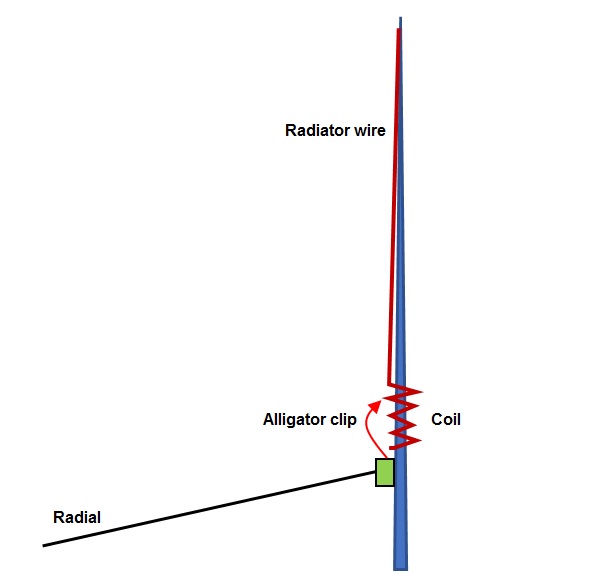
Although placing the coil in the center of the radiator increases the radiation compared to the base loaded version, due to the fact this antenna will be used for portable, on an uncontrolled variety of soil, I decided to finally put the coil just down, at the feedpoint so that I could tune the coil with ease, setting the inductance by means of an alligator clip.

This scheme gives a basic idea of the design:

Evaluation of Radiator length variants

According to my constraints, the wire length should be 3 meters. This is already an improvement compared to some other shorter whip antennas (Elecraft AX1 / AX2 in example are 1,15 m long).

Nevertheless, I considered alternatives to enlarge the wire length without changing the size of my pole, that is 4 meter long, and my elevated feed point kept at one meter over ground.

One solution I simulated is to put a wire zigzagging the pole, like this:

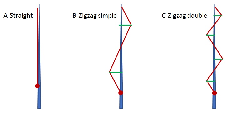
I measured the resulting wire length of such scenarios and, using horizontal spreaders of 40 cm (green arms on the scheme), the achieved lengths for either design were:

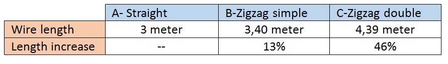
The length increase is little on the Zigzag simple version but considerable for the Zigzag double.

Does it worth preparing this increased length version?

Bearing in mind that I want this antenna for restricted spaces, the zigzagged versions would probably require additional setup time on a summit to properly deploy it and could suffer from a potential interference from branches and vegetation. Installation would be time consuming and probably annoying, putting on risk the success of the radio activation.

Therefore, I decided it wouldn’t worth the effort to extend the length so I better use a straight wire instead. It’s better to keep the design simple although this evaluation was a good exercise to look for such alternatives.
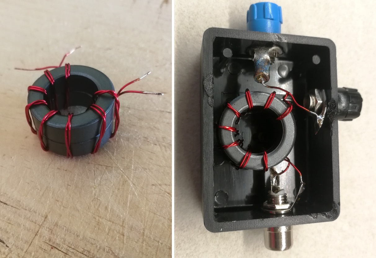
The coil

My friend Mique, EA2EUS, was kind to provide me with a 3D printed coil former. He printed the SA2CLC coil former, available in thingverse web:

https://www.thingiverse.com/thing:4525375

This former is a bit oversized for a QRP antenna, but it is robust and will resist many activation in the mountain without being damaged.

Main dimensions:

  • Diameter: 62 mm
  • Coil height: 83 mm / Full height: 121 mm (after cutting off a part I didn’t need)
  • Coil turns: 28

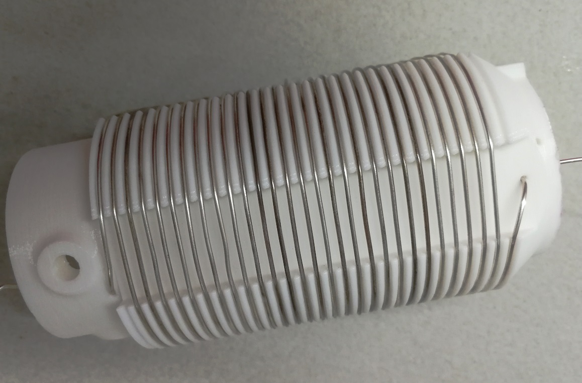
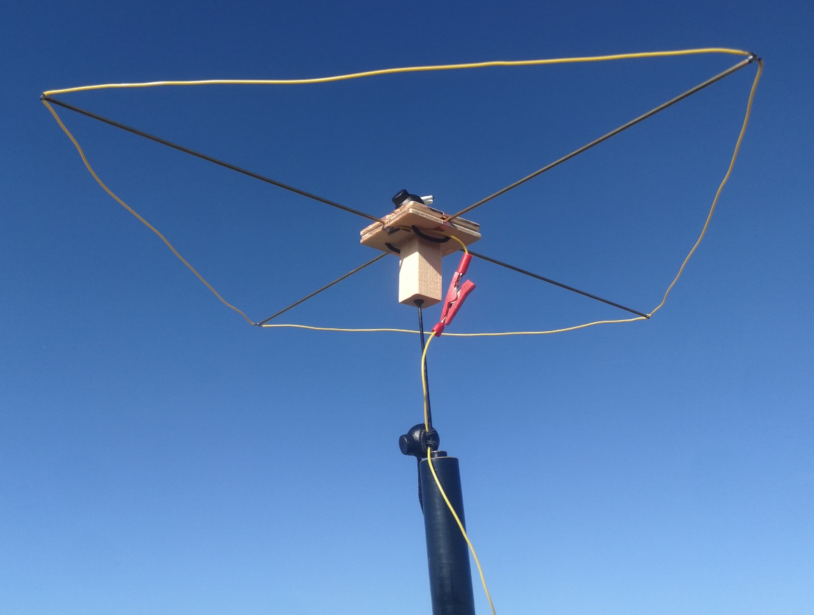
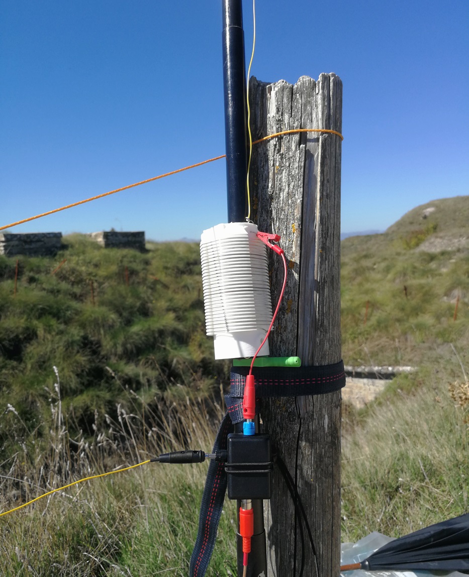
I easily winded a solid conductor of 1 mm diameter. Using my LC meter I measured around 26 uHenry. It looks a good coil for the job. The separation between turns allow using an alligator clip to tune it. See how it looks assembled in the field:
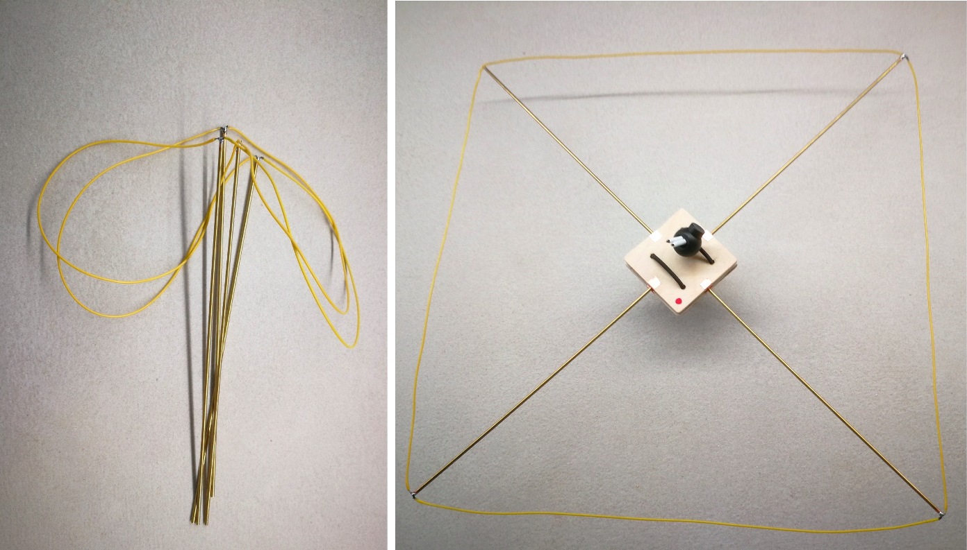
The radial

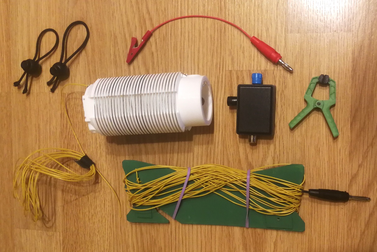
I cut a bit over 10 meter of lightweight antenna wire from Sotabeams (yellow cable). This is a 7/0,2 mm (0,22 mm2), approx. 24 AWG size, with PVC insulation and 0,92 velocity factor.

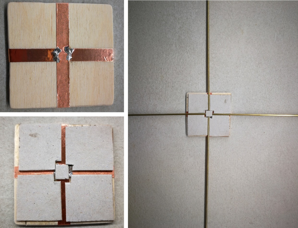
Then I prepared a cardboard wire winder. I did it very simple and protected with acrylic paint. It’s not the best solution but was easy to design and I could go out for a field test.

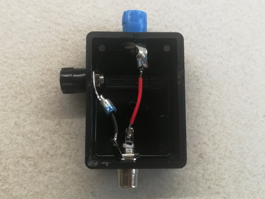
The connector box is very simple, and perhaps I will fit a toroid choke on it.

The whole system (except the pole) weights 254 gram, not heavy!
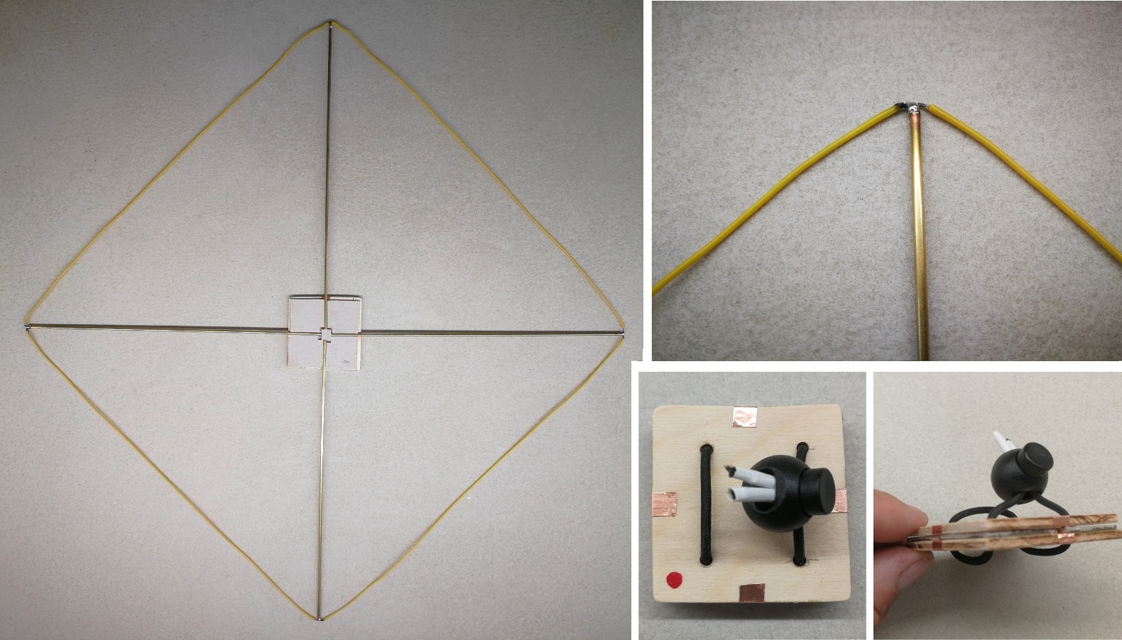
This is the complete antenna ready for evaluation:

Testing the antenna

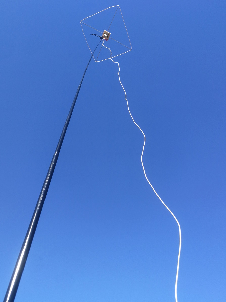
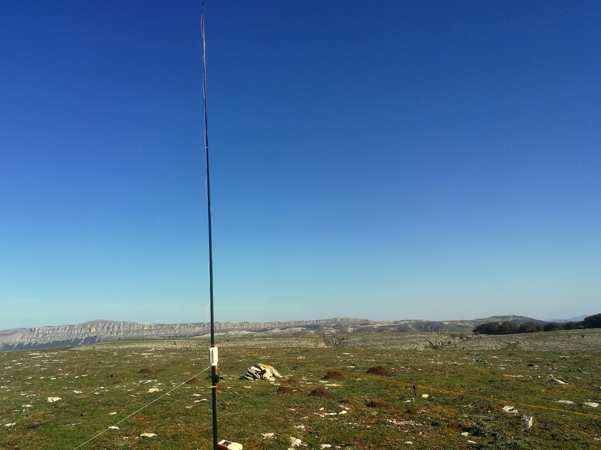
I tried the antenna on EA2/NV-119. It is not a restricted summit but wanted to check how the antenna was performing. Activation date: Sept-29th 2023.

Set up was very easy and fast. I tied my pole to a stick, extended the antenna up, placed the coil, and added a small box for the connector and the radial, extending it towards Europe.

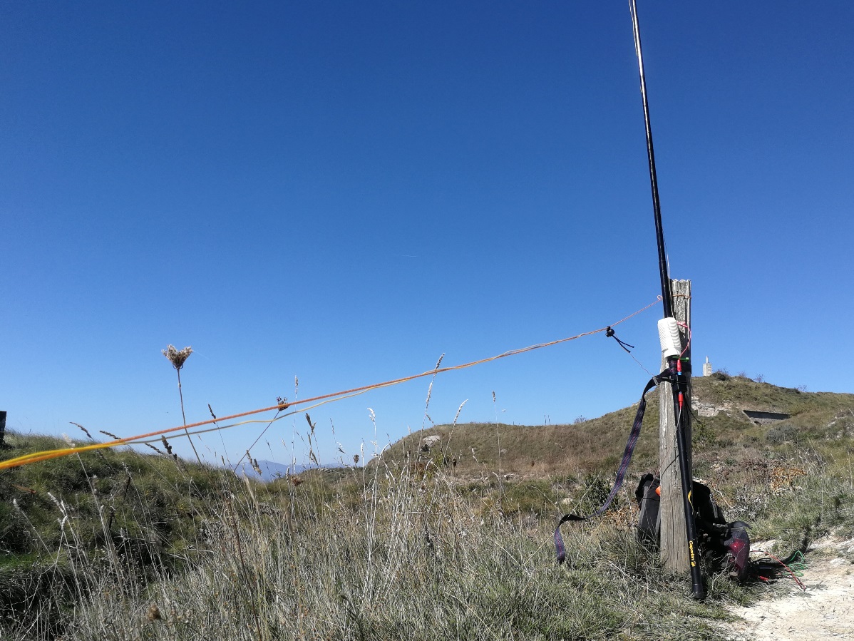
The radial wasn’t elevated all its length but sloped. I put a long cord so that I could hang the radial on it and extend or reduce the radial using the winder, depending on the band of choice. The far end was around 15 cm over ground.

I decided to run on 18 MHz CW first. Tuning was easy looking to the maximun noise with the clip on the coil. Later I ran on 14 MHz and finally on 10 MHz.

See the RBN spots I got per band:

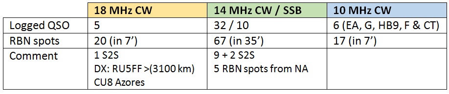
I had a few qso on 18 MHz with some DX, and moved to 14 MHZ whereI had a good feeling with the usual stream of chasers, great.
I spent a few minutes for the final part on 10 MHz: there felt the band was less live, perhaps a reduced RX as expected due to the short wire length for this band?
After 1h 30 min activation I closed my log with 53 being 12 S2S. I was happy with the result .

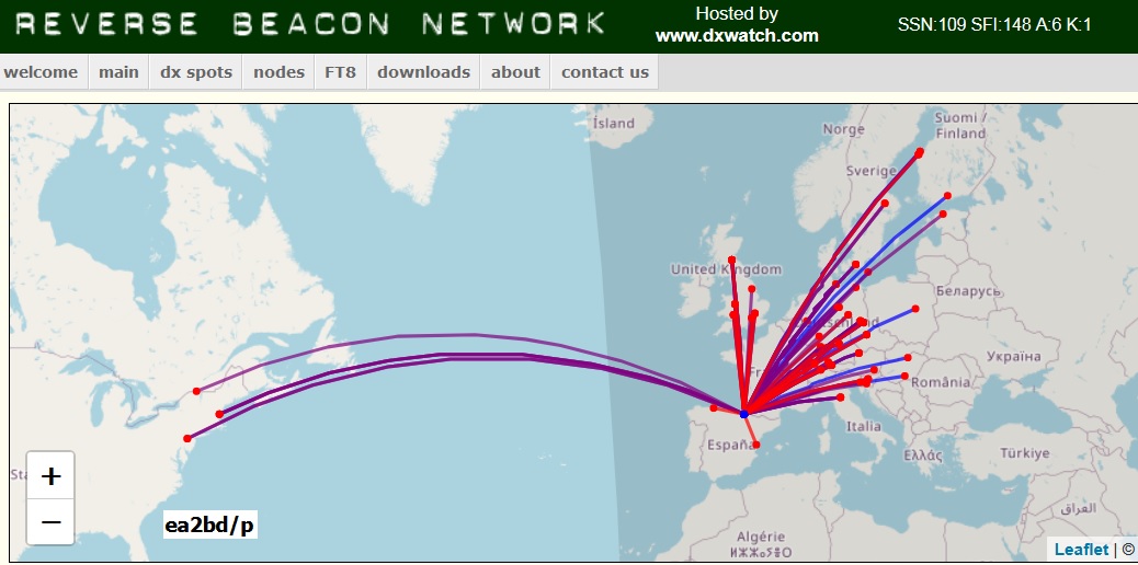
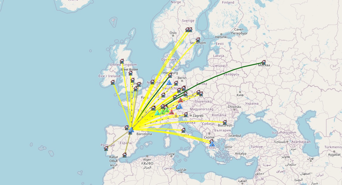
See how the RBN Spots map agrees with the resulting QSO map:

Future development

  • Other bands

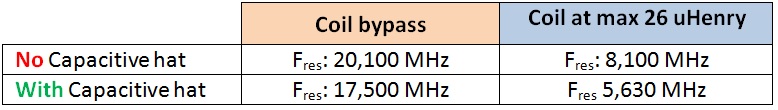
I tried to tune the antenna on 21 MHz without success, SWR was 5,5 at best. Is perhaps the wire too long for the band? That is pending to check.

I couldn’t tune the coil for 7 MHz either. Minimum resonace at maximum load of the coil was 8 MHz. Although the performance in 7 MHz would be presumably very low, I should add more inductance (an additional coil in series) or perhaps trying a capacitive hat on top. That is pending to check too.
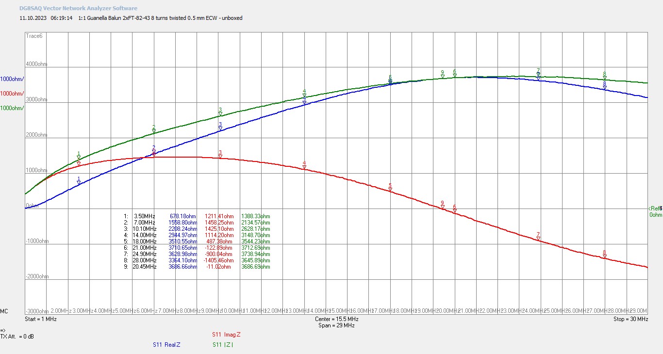
  • RF common mode

During thee activation I saw variations of SWR at times while transmitting.

I tried measuring SWR and impedance on a park another day and experienced difficulties to read stable values in my antenna analyzer. The Z was changing up and down. My feeling was there is RF flowing through the coaxial. Perhaps I will add a FT82-43 choke at the connector box to see if this cures the issue.

I must run a real test on a restricted summit in the future to confirm these satisfactory preliminar results.

73 Ignacio

31 Likes

Nice work, Ignacio!
Also, good that you will be making the antenna work on 7MHz, by some means. At 8 MHZ and higher frequencies, trees, especially those with a lot of vertical structure, interact greatly with vertical antennas, creating deep nulls in the radiation pattern.
See: FULL-SCALE PATTERN MEASUREMENTS
OF SIMPLE HF FIELD ANTENNAS IN A US CONIFER FOREST
ARPA / SRI circa 1967, and includes work done in S.E. Asia.

1 Like

Hi Ignacio, and any others interested, a popular portable vertical antenna in VK is known as the squid pole that covers 80, 40/ 30, 20 15 metre bands. It was developed by VK7JJ. Do a search for “vk7jj antenna” you will find many links to his site. It is a great vertical and many ham in vk have have built it.

PS: you can print out the 2 pages of the details.

73 Geoff vk3sq

5 Likes

Nice article Ignacio.
I will add a comment about the commercially available loaded verticals. The cheaper ones have a telescopic element and a link wire to short out sections of the loading coil - with these models you get “near to” the required frequency by shorting out the coil and then adjust the length of the whip to get into the amateur band. While these work on Rx their radiation capabilities on Tx are degraded the shorter you have to make the whip.
The other approach used is to have a telescopic element which is always fully extended and there is a slider section to connect to the loading coil which tunes the antenna. These work very well in comparison to the first type.

I have an HF-PRO-2-PLUST from the Spanish company Komunica Power (unfortunately now copied by Chinese/Taiwanese and sold under different names through some well-known importers).

Building your own brings further advantages as you can maximise the length of the driven element to make the antenna as efficient as possible.

As you say all of these options need a good set of radials of at least (in my experience) 3 metres long and at least 6-8 of them.

73 Ed.

4 Likes

Hello Ignacio

Thanks for the report.

It’s good to have a (small) lightweight antenna… This is not only helpful when setup options are limited, but also to keep your luggage smaller and lighter on more strenuous tours… (e.g. to take more water with you)

73 Armin

5 Likes

A great write up Ignacio and an interesting project.

It may be worth trying a shorter radial on 21MHz and maybe a ground tunner for 7MHz. It would be interesting to see if the balun helps. I did some similar experiments in the summer with a 4m vertical, ground radials and a home made GTU based on a Peter Parker, VK3YE design but using a tapped toroid inductor. The GTU seemed to make a significant difference on 40m, with reduced benefits on the higher bands. At least one commercial GTU just uses a switched toroid inductor.

Thank you for sharing. Kevin, MW0KXN

2 Likes

Exactly my thinking when I asked about people who had produced DIY clone AX-1 type antennas. I spent sometime Googling and found a few designs to try specifically as I found a 1.4m telescopic whip to use with a suitable loading coil. There are some summits where something small is needed or can be deployed quickly and is not visually obvious. Possibly such that you can deploy it from your back pack in a man-portable mode. i.e so cafe owners in The Vosges don’t come over and chase you away :wink:

As you say, the problem with loaded antennas like these is they can work but often at the expense of radiated power. As long as you accept these antennas have limitations then they can be viable for specific environments.

I normally use Inv-V dipoles but recently have been playing with a trapped EFHW in sloping inv-L (similar to Heinz’s HB9BCB’s antenna). The inv-V dipole is exceptionally repeatable and tame on all kinds of ground. I have much less experience using the EFHW so I’m still learning why and how it works.

I do have other antennas and for a while I used a Buddistick clone on 30/20/17m primarily. When conditions were good (ionosphere and ground setup) it was good for unexpected DX. It worked but it could be a pain to get a match. Sometimes it was the ground and sometimes, like you think with your design, it was RF feedback. Repositioning where I placed my 90kg “fatty-salty-water” body could often effect a big improvement. The large loading coil for 30m meant that whilst it worked it didn’t seem a particularly “hot” antenna. My Buddstick clone was fed about 50cms above ground and the coil was about 1/4 up the radiator.

In all these things it is all well and good knowing that antennas are bits of wire with possibly some kind of matching unit to get to 50+j0 ohms what is more important is seeing the SOTAfication of the design. i.e. how is it physically realised so that you can deploy it on a hill in rain, snow, wind when wearing gloves. How do you make it so it doesn’t fall apart when you set it up and take it down.

So thanks for showing all of the components and how it is rigged. Once you see how one person has done it, you can copy it and maybe try to improve.

:+1:

5 Likes

Hi Ignacio,

Thank you for showing us your solution, very interesting!

I experimented as well with such kind of antennas, also mainly for space restricted summits.

I wanted an antenna that is usable between 40m and 6m, without the need of a tuner. It should be easily and fast deployable, either by a composed earth stake, some stones or supported by the backpack.

Like Ed @DD5LP, I experimented with the well known Kommunica/Gabil/Sharman branded antenna, or in my case, with a clone from WIMO.

The whole antenna system, including a ground spike, 3m of RG-174, 8 radials and wire winder weights in total 740g and needs little space in the backpack.

I created a short video that may give you some inspiration for your own solution:

The video description contains further information about all used parts.

73 Stephan

12 Likes

Hi Stephan,
Yes, that is one of the copies of the Komunica Power HF-PRO2-PLUS-T design (I talked with the Komunica CEO and she said they had the antenna built to their design in Taiwan to avoid IP theft which often happens using manufacturers in mainland China). That was the case for the last 4 1/2 years but 6 months ago, these copies started appearing on the market.
I believe the “Gabil” branded version was available at Friedrichshafen for €99 instead of the €150 price from Komunica Power.
The new MFJ 1898 appears also to be a copy, except it has a 3/8"-24 (aka CB) mount instead of a PL-259 - perhaps they think that makes it OK to rip-off someone else’s design if you change it a little?

As I do not seem to have a lot of luck with stakes and hard stony ground, I use a modified photo tripod rather than a stake with my antenna and 8 x 3 metre-long radial wires and this antenna performs better than it should! Three weeks ago while on Cyprus I worked into Australia three times with 20w of SSB on 20 metres (and those VK stations called me).
When in a good (quiet) portable location North American contacts are also easy to get - in both cases, you, of course, have to be on the air at the right time for the propagation and the chaser needs a good antenna system.

73 Ed.

3 Likes

Hello Ignacio,

thanks for this nice and interesting report! And congrats on the good results you achieved using it in the field.
It is interesting that you went for the solution with a short vertical wire instead of a telescopic whip. My thoughts went into the same direction when I was searching for a similar antenna, not too long ago. The biggest difference is maybe that I wanted to use it with the MTR-3B and thus only needed 40, 30 and 20m. The protoype is still somewhat provisional but it worked (and survived!) on two activations in harsh alpine environment.

Keep up the great work and cu soon!
73, Roman

3 Likes

Thanks for the info Ed, I didn’t know the whole story!

And like you, when I first saw this MFJ 1898 in a video, I had the same thought.

Now with the improved conditions on the higher bands, such slightly shortened antennas are fun for DX, especially on bands that your other antennas can’t cope well with (12m in my case).

73 Stephan

1 Like

Thanks Ken, I found the referenced article; interesting paper. I’ll take into account and avoid dense trees areas whenever possible.

Thanks Geoff for your input: interesting antenna despite it is designed for 80m and up, and I don’t intend to operate that low. The squid pole requires a large pole for such a low band. Anyway, I rode it with interest.

Thanks Ed for your comments on whip antennas: sure that a proper extensive ground system make the work best.

Thanks Armin, yes, that’s the idea, to carry this one for some long tours, for tiny summits or for rocky summits not safe to deploy a proper large wire.

Thanks Kevin. Indeed a GTU would help dealing with fine tuning and to get rid of coil adjustments.

Heinz, HB9BCB, our prolific antennas guru, proposed to prepare a set of base fixed coil per band and use a tuner at the feed point exactly for such purpose. So far I will try using the design as is, because I’m missing a small tuner and I prefer to try tuning on the coil if I can.

Hi Andy, here I’m missing some kilo as I’m a bit fit, so my body structure won’t improve the impedance/SWR that much, I’m afraid. I’m glad to share the thoughts and experiences; I’m learning a lot by reading other’s experiments here in the Reflector.

Hi Stefan, thanks for your interesting video; your Wimo telescopic looks good with that large whip. It’s good to have such simple antennas available. As Ed suggested, I find difficulties using the stakes on rocky soil. We have to manage for putting antennas up on a variety of grounds.

Hallo Roman, thanks for your interesting version. I wanted also to do mine center loaded but you see I finally refused for ease of tuning control. Your input is much appreciated.

I have started preparing some modification and I’ll share them soom here.
73 Ignacio

7 Likes

Hi Ignacio,

I’m a big fan of ground spikes, because they work 90% of the times as intended for me, making the setup quick and don’t need much space in the backpack (with a wine cork as protection). Not exactly the same, but in a similar category goes the Decathlon mast holder.

For the remaining 10%, e.g. with rocky or sandy soil, I always found a solution, for example as shown in the video with the support of the backpack, or simply wedging the spike in a pile of stones.

73 Stephan

1 Like

Hi Ignacio,
I’d want to do more than just click the like button on your latest post (which I have done) but also go on to say that your post is a perfect example of how people’s suggestions are clearly being considered (applied if helpful) and then added into the updated design. Your final design will be a “community effort” and I think that is wonderful and an example of how well amateurs from different technical backgrounds from different countries can work together to contribute to the final solution.

Well done Ignacio
Ed.

3 Likes

Part 2: short vertical antenna improvements

I had some free time this week to prepare the two modifications listed at the end of my first post, as I describe now. I’m excited to say the antenna is doing better with these two addition.

1) Common Mode choke

I found an old thread were HB9BCB described how to prepare a useful low power choke with a pair of stacked FT82-43. The coil is made with 8 turns of twisted pair of magnet wires.

The VNA plots of Heinz were good. This is the approximate Zcm (frequency dependent) of such choke:

Heinz also suggested that 11 turns would even provide higher blocking attenuation, but I decided to try the easy 8 turns version.

I built that CMC and inserted it into my connector box.

We will check later if this improves my antenna.

2) Capacity hat

The first activation with this antenna (see top of this thread) showed that the lowest resonant frequency achieved with the maximum loading of the coil (28 turns, 26 uHenry) was around 8 MHz. I couldn’t tune down to 40 meter band.

I reasoned I could add another extra coil in series for this band, but instead, I decided to build and test a capacity hat. This one should be a lightweight and easily dismantable version for portable.

I checked my junkbox and found some useful parts I could use:

  • 2 mm diameter brass tube. I cut 4 spreaders of 20 cm long.

  • Yellow thin wire. I soldered the ends of the spreaders to form an outer square.

  • Plywood and a dowel for the center support.

  • Copper adhesive foil, to warrantee the electrical contact between all parts in the center.

  • Elastic cord, 2 mm diameter and cord lock stoppers. That holds the plywood as a clamp for the brass tubes.

  • Alligator clip to connect it to the antenna radiator.

Images are self explanatory.

As you can see, the cardboard serves as a guide for the brass spreaders to keep them straight.

I use plywood on top and bottom held by the elastic cord and the locker.

The brass tubes can be removed. This is a foldable capacity hat that is assembled in a minute by hand!

Total weight is 38 gram. Capacity hat geometry is square 30 x 30 centimeter; small.

Activation test.

I agree with Jorge, EA2LU to do a joint activation on October 12th 2023 on EA2/NV-053.

This is not a restricted summit but I just wanted to check if the two changes improved the antenna.

I installed the antenna with ease and extended the radial, keeping it quite straight and parallel to the soil. There was a light breeze and this kept the radiator separated a few centimeters from the pole.

I was afraid the wind would cause some troubles now that I had the Hat on top, but my 4 meter pole was straight and stable. Seems the reduced diameters and light wire gauge wasn’t obstructing the air flow that much.

I checked first with the antenna analizer to see the resonant frequency: (round values)

I was very happy to see that the capacitive hat had reduced resonant frequency about 2,6 MHz. Now I could use the antenna for 7 MHz!

In the other hand, when the antenna wasn’t connected with the hat I could just go up to 20 MHz. Therefore I should add a link on the radiator to shorten it and be able to operate on 15m – 10m.

With the capacity hat on, I annotated the turns required in the coil for some bands:

  • 7 MHz: 16 turns for CW / 15 turns for SSB (12,1 / 11,1 uHenry)
  • 10 MHz: 7 turns (3,7 uHenry)
  • 14 MHz: 2 turns (0,5 uHenry)

What about the Choke? The measurements in the antenna analyzer were stable compared to the previous test without the CMC. Impedance was around Z=50 + j0 in all tuned bands and the readout values were not fluctuating anymore.

Adding the choke was essential for a stable operation with this design, preventing from RF back in the coax.

The activation

After the measurements it was the time for the SOTA activation. I decided to start in the worst scenario, that is 7 MHz SSB. I set power to 7 watts, selfspotted and started CQing.

I was very happy to log 50 QSO, all EA / EA8, in 22 minutes. Reports were okay and I felt like the antenna was performing well, no spaces nor repeats after my reports and over. Seems the capacity hat did the deal, very good for a 3 meter radiator in this band!

I ran a bit on 7 MHz CW and there I logged a few more, now including HB9.

After, I tried 10 MHz and got 11 EU QSO, including 4 S2S summits with @EB2GKK, @EA4DOS & @EA4DON, @IW2OGY and @EA3M.

Jorge had already ran on 14 MHz, it was a bit late and I just added a quick QSO in 14 MHz to work @HB9BHU S2S before calling it a day.

All in all 69 QSO this time. I felt very enthusiastic with the positive results.

Future development

The antenna is quite okay now, but I must add a link in the radiator, at about 2 meters off the start so that I can cut and run the 15m – 10m bands.

I have the antenna ready for any true restricted summit activation.

73 Ignacio

P.s: whenever possble I’ll try recording a video for the setup and tune process. We’ll see…

14 Likes

Your brain doesn’t stop, Ignacio!

I enjoyed watching your post, great proyect and well done. Congrats!

2 Likes

Hi dear Jon,
you know, there are never enough antennas in the backpack!

Glad you find it interesting. Un abrazo

73 Ignacio

4 Likes

Nice setup and great video. Have you experimented with aluminum window screens as counterpoises? I’ve seen this on the POTA side of things lately. It’s probably too big for hiking in, but maybe cut down?

1 Like

Very interesting, it was a pleasure to help you testing. Congratulations on your new antena and thanks for this (another one, actually) great post!

4 Likes

Hi Ignacio,

I checked first with the antenna analizer to see the resonant frequency: (round values)

I was very happy to see that the capacitive hat had reduced resonant frequency about 2,6 MHz. Now I could use the antenna for 7 MHz!

I suggest to increase the capacitance hat just a little more and get also active on 60m! You are just 300 kHz off. Maybe you can fit another turn on your coil former. That would also do.

Could you please report what the usuable bandwith (e.g. SWR <1:2.0) of your vertical is.

73 Heinz

2 Likes