Qué buena pinta tiene Ignacio! muy buen trabajo!
72. Manu.
1 Like
Hi dear Heinz,
I will do these measurements whenever I can. Some rain forecasted on the next days, I wait for a right chance.
73 Ignacio
2 Likes
Part 3: Antenna bandwidth measurements
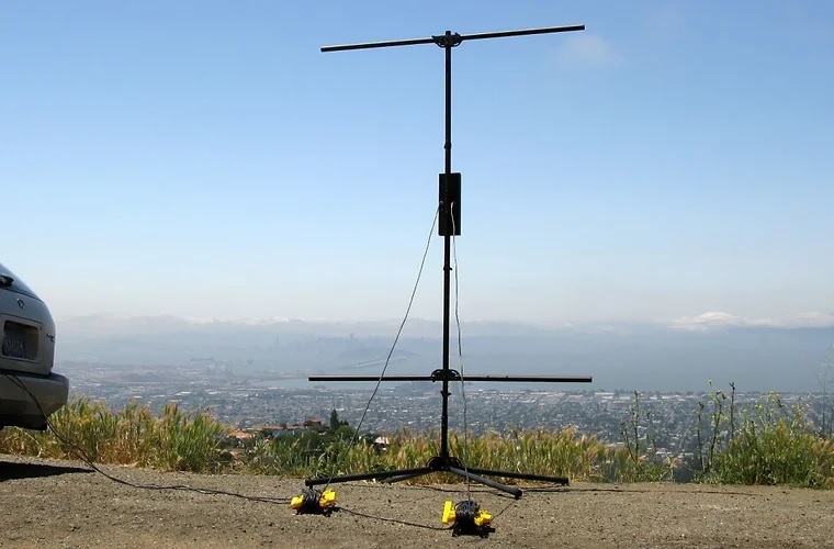
According to OE5EEP Heinz’s request for bandwith data of this antenna, I went to my test bench on a park in my town, installed the antenna and measured the SWR levels band per band using my Rigexpert AA-54 analyzer.
Here you have the results:
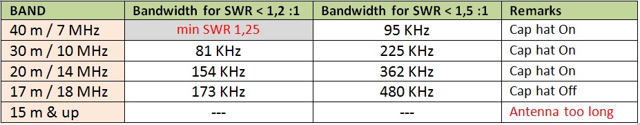
Bandwidth is very wide for 10 MHz and up, covering the whole band.
Only in 40 m, as expected due to the inductance required, the full band is not covered with an SWR < 1,5, but the achieved bandwidth is not that bad. Just a slight fine tuning of the radial length could be necessary to improve SWR when moving from the lower to the higher extreme frequency.
See pictures of the SWR sweep while testing:
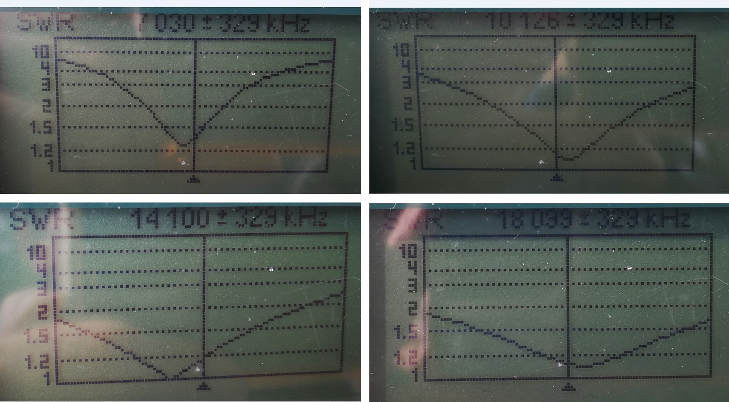
I still need to add a link on the radiator to cut out some wire in order to make the antenna work in 15 m band.
I took the chance of the testing to record a video. In the next days I will edit the footage and put a link here.
73 Ignacio
8 Likes
I have dealt with this problem for mobile HF operation. I use an antenna that is 2.16 m (= 7 foot 1 inch) tall on the roof of the vehicle. The loading coil I use is manually tuned with a jumper, much like yours. I’ve made over 12000 QSOs with this antenna on 80 m through 10 m.
The phenomenon at play is this: even with a jumper bypassing all turns of the coil, the coil is still contributing significant inductance.
If I’m reading your description correctly, your vertical is 3 m long, which is a quarter wavelength at 24.9 MHz and quite a bit shorter (by 16 %) than a quarter wavelength at 21.1 MHz. If you can further reduce the inductance of your coil, resonance on 15 m, and maybe 12 m, should be possible without reducing the wire length.
To lower the inductance further, you have to use multiple jumpers tapped to roughly-equally-distributed points along the coil, like this:
Or, construct a daisy-chain jumper with multiple taps, like this:
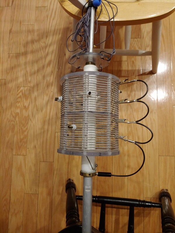
The more taps distributed along the coil, the lower the inductance for a given position of the upper-most tap.
The highest frequency at which I’ve been able to resonate this antenna is 30.1 MHz (not that I operate there, but I took measurements with the antenna analyzer for curiosity’s sake). This was achieved with the four-tap clip jumper in the second photo bypassing the entire coil combined with the three plug-in jumpers placed as in the first photo.
30.1 MHz corresponds to a quarter wavelength of 2.49 m in free-space. The antenna, at 2.16 m, is shorter than that by 13 percent, so the coil is still contributing some loading effect even with a total of seven bypass taps. Perhaps some of this loading effect is not only lingering inductance but a slight capacity-hat effect from the coil and jumpers.
All of the above is without an (intentional) capacity hat. At the other end of the dial, to resonate the antenna on 80 m, I put a capacity hat on the top of the antenna. On that band, I use a single jumper bypassing about 1/4 to 1/3 of the turns; my usable bandwidth per tap location (VSWR < 2.0) is only 13 kHz (at the CW end) to 17 kHz (at the SSB end)!
5 Likes
Hi Matt,
that’s an interesting contribution, glad to find another happy user of a short loaded vertical.
I’ll try testing your mod for the coil and see what happens.
73 Ignacio
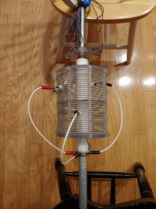
There we go, now on your video player:
")
You can get the idea on how it’s setup.
73 Ignacio
9 Likes
Hi Ryan,
Sorry for the late reply. No, I haven’t tried any kind of screens. I think it’s a good alternative, probably even better than radials, but not the best solution on a small summit. It would also take up more space in the backpack, which I try to avoid.
73 Stephan
1 Like
That makes sense. I wonder if a smaller sized screen would still be as effective? I may have to figure out a way to test that. Maybe WSPR mode? Just thinking out loud (or whatever the digital equivalent is).
1 Like
Late reply here - I especially registered for this post. I was first licensed in April 1974 but recently took up HAM radio again after a hiatus due to work commitments and I had to search for an antenna that was relative small and potentially portable.
Have you considered the Force 12 Sigma 5? The instructions with sizes can be found on the web. A later version is the TWA2010 antenna. Testing and measurements were done by NE1RD and written up in his blog “antennas for 100 pound dxpeditions”.
I’ve build the Sigma 5 and like it a lot. Two problems had to be solved: the horrible coil arrangement and how to get the T junctions economically.
Coil arrangement: I use toroids in a polycarbonate enclosure and use toggle switches to short the coils both for frequency selection and for impdeance match. A kind of “manual” ATU setup. Maximum value 5uH for the band and 0.96uH for the impedance. Toroids are T80-2 and T94-2 with a FT-140-43 for choke.
Originally I was going to clone the toroids setup from the Elecraft KAT-100 but by mistake (what turned out to be a blessing) I ordered the T80-2 instead of the T80-0. The blessing is that the T80-0 is very sensitive to winding technique and to nearby objects.
The other tidbit of information is that according to Amidon with small cores the Q is highest towards the top end of the toroid frequency range and with big cores towards the low end. This means the Q is higher with the T80-2 than with the T80-0 which is important for maximum efficiency.
The T-junction issue was solved by going on the favourite auction site and search for handlebar bicycle stems and look for one at reasonable price with a 28.6mm stem and a 25.4mm handlebar.
One can juggle with different tube diameters (e.g. have a larger one that the 28.6 will fit into) and then make it portable by having shorter lenghts of tubing and using quick lock bicycle seatclamps to clamp them together.
A few pieces of fibreglass tubing (make sure no carbon in it since the bottom one is at high voltage) are used as insulators.
I’m too old to make this into a commercial venture (plus healht issues), not to mention freight issues shipping from New Zealand going to be an obstacle so perhaps a suggestion someone else?
73’s, John
2 Likes
Forgot to mention that I switch each leg separately: i.e. two rows of toroids with each their own set of switches. The impedance match is set up in a way that it never can be shorted: I’ve got permanently a 0.32uH in series (which cannot be shorted) with 0.04uH, 0.08uH, 0.16uH and 0.32uH.
I’ve made notes of the settings of the switches for each band after an initial “tune up” with a nano-vna and later verification with my IC-703+.
73’s, John
2 Likes
John, I’m glad you pointed out the use of toroidal cores, specifically the Amidon Txx-2. I’ve also had good experiences to use it with shortened antennas and as a CWL trap.
73 Chris
2 Likes
Hi John,
thanks a lot for your interest and contribution to this post.
I saw details on the vertical dipole antennas that you mention. They are interesting.
Most Sota operators use simple wire antennas, frequently home built. Those Force 12 Sigma 5 or the TWA 2010 are commercial grade, probably for expeditions or for a longer activity, but surely these could be homebrew with wire.
My simple vertical, base loaded is a cheap and dirty multiband solution as its main purpose is to allow for a quick deployment, but I save your proposed design in my options list.
I guess that building it with wire would be a bit tricky requiring some spreaders as for the base and top arms, but anyway it’s an interesting short antenna and a curious multiband center loading system.
Concerning the toroid inductors, I imagine you mean some kind of multiple selectable inductors like in this picture (courtesy DL3TU):
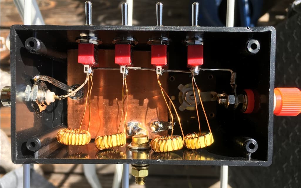
Thanks again for the idea John, 73
Ignacio
4 Likes
Dear Ignacio,
I’ve got one row of 5 toroids: 0.32uH (connot be shortened with a toggle switch), 0.32uH, 0.16uH, 0.08uH and 0.04uH that each can be shortened to make any value between 0.32uH and 0.92uH. This is the one for impedance matching. I could (should?) have made the second 0.32uh 0.16uH instead (making for a total of 0.76 and instead of using two 0.32uH use two 0.16uh toroids). The first 0.32uH is there in order that never the coax could be shorted.
Then there are two rows of toroids: 2.6uH, 1.3uH, 0.64uH, 0.32uH, 0.16uH, 0.08uH and 0.04uH that determine the lenght for any frequency below 30Mhz.
Each of these toroids have a switch that shortens them as required. Basically you’ll have any value between 0uH and 5.14uH to lenghten the elements.
I switch the top and bottom element seperately in order to be able to compensate with different grounds or different heights above grounds.
Juggling with some different tubelengths can make the individual parts as big or small as wanted. Sinced I want to be able to take it in the car the longest length is just under 130 cm. (broken up at the t-joints and by the matching unit. At the matching unit I use two stainless steel T-Bar hose clamps and I’ve use some silver solder for attaching the cable that goes inside to these stainless steel hose clamps.
The bigger diameter of the tubing makes for some wider bandwidth.
A very long time ago I gave up on EFHW since it invariably brings RF to the rig and that’s something I under not any circumstances can have due to health issues: I’ve no immune system and RF affects my bloodcounts and the frequency of the mediations I need to take to stay alive.
73
John
1 Like
So how far do you have to be from the antenna on HF to be out of the effect of the near field?
I’ve build in a FT-140-43 choke in the matching unit, go horizontal for 5 meters to a fibreglass stick 9mm dia, a FT240-31 with 8 turns, drop to ground and then 10 meters to the IC-903+ running 10 watts. Have not had any noticeable changes.
At home I raise the antenna to just above gutter height - we have a metal roof - and flick the coax over the apex to the other side of the house where I feed the coax inside. The roof gives me some reflection for NVIS and some reflection in the right DX direction. No chokes required this time and no measurable RFI inside.
As long as I keep power low and keep at least 10 meters distance when outside (I keep close to 15 meters) I am OK. In the mid 70’s I had a Yaesu FT-7 and worked the worked with 10 Watts on a simple folded dipole made from 300 Ohm TV twin lead. Diehard low power here.
73’s John
1 Like
When my hemoglobin level and the immune system dropped in 2005 due to blood cell malformations in the bone marrow and possible causes were looked for, understandably the 30 years as a radio amateur (no VHF/UHF …) were also discussed, but then clearly ruled out.
Although the life-saving HSCT in 2005 caused very serious side effects in the first 4 months, a complete remission was then noted, which fortunately has now lasted for 19 years (without medication).
BTW, If that were to happen, I would then have to think about whether I should dedicate a birthday activation for 80 or 20 years of life … that could possibly simplify the selection of the summit according to the idea of Guru, EA2IF, hi.
I wish you continued well-controlled disease progression, John.
73, Heinz
1 Like
Apparently (statistically) radar technicians have a higher incidence of leukemia / bone marrow cancer. I did at one stage use regularly mobile phones and would feel my ear getting warm and to a lesser extend that side of the head. Don’t know how much influence that has had. But fact remains if I am exposed to RFI or too close to an antenna with a 100 Watt transceiver then the next weekly bloodcounts are way down.
Congratulations on the HSCT, it is not something the doctors here want to undertake due to the risk factor. I might not be a suitable candidate either.
I’ve been going like this for the past 21 years but the Pfizer vaccination worsened the whole lot: I’d to increase the frequency of my mediation three fold, grrrr… But I’m still here and enjoying life, there are many worse off.
73 John.
1 Like