Motivation
Back in October 2023 I had prepared a short base loaded vertical. It’s target was to be used when in a restricted space summit.
I purposely decided to add a single elevated radial and it worked fine for what it was (a 3 m long radiator). Tuning the antenna for each band required tuning the base coil plus changing the radial length as that one is resonant (+/- quarter wavelength).
The antenna worked between 7 to 18 MHz. Concerning the 7 MHz band, I suspect that the elevated radial lengthened to about 10 meter long for this band was mainly responsible for the radiation, more than the loaded short 3m vertical itself.
Detail on this v.1 project here: V1
What’s the reason for a new version v.2 then?
The tuning process in v.1 was tedious and not fast, requiring two changes (the coil clip and the elevated radial) which was time consuming and not so easy to settle in small summits.
Then I decided to update my short antenna with these constraints:
- Keep on using a 4m long fishpole.
- Enlarge the radiator length from the original 3 m long up to 3,8 m.
- Get rid of the elevated radial and use 4 short 2,5 m radials instead.
- Add a new concept for the top capacity hat.
By placing the 4 radials on ground I would avoid tuning them, and then just a tap change in the coil would allow a fast band change: much better!
Preparation: the cap hat
A cap hat is a nice add on to this sort of short antennas. The hat doesn’t radiate RF but it facilitates the flow of electrons up to the top of the antenna: the flow would be reduced if no hat was put on top.
The cap contributes significatively to reduce the required inductance in the coil and the antenna act like it was a bit longer, therefore improving its performance.
The cap hat in v.1 was made with 4 brass rods but I had to put in its center support, thus requiring some assembly time, again.
I decided to try an innovative design to get rid of the assembly. I wanted something light that I could carry in my rucksack ready for an instant connection.
I found some spare plastic dish at home and I reasoned: why not?
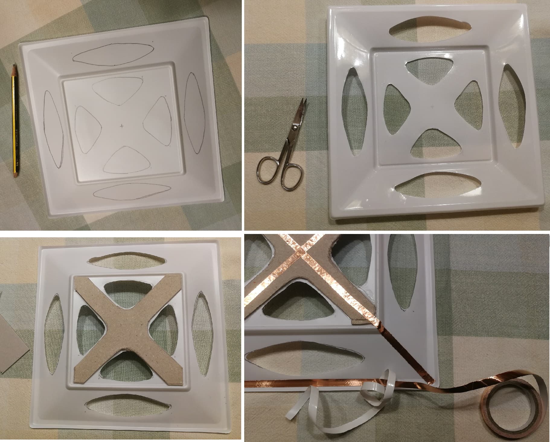
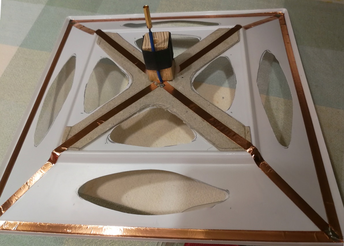
To prepare this Cap hat (the UFO, you’ll see why…) I used:
- A square plastic dish of 23 x 23 centimeter (I cut out some holes to reduce wind load)
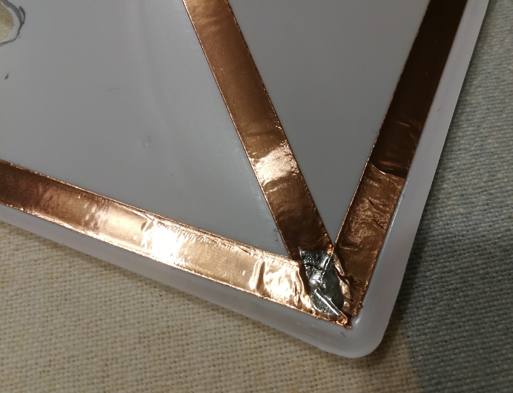
- A 6 mm wide adhesive copper foil, stick in the outer prifile and in the center cross
- Greyboard for base reinforcement
- A square dowel with a 5 mm hole
- Small connection wire with a 3mm female bullet banana
- Acrylic paint
Construction was fun and some pictures describe it easily:
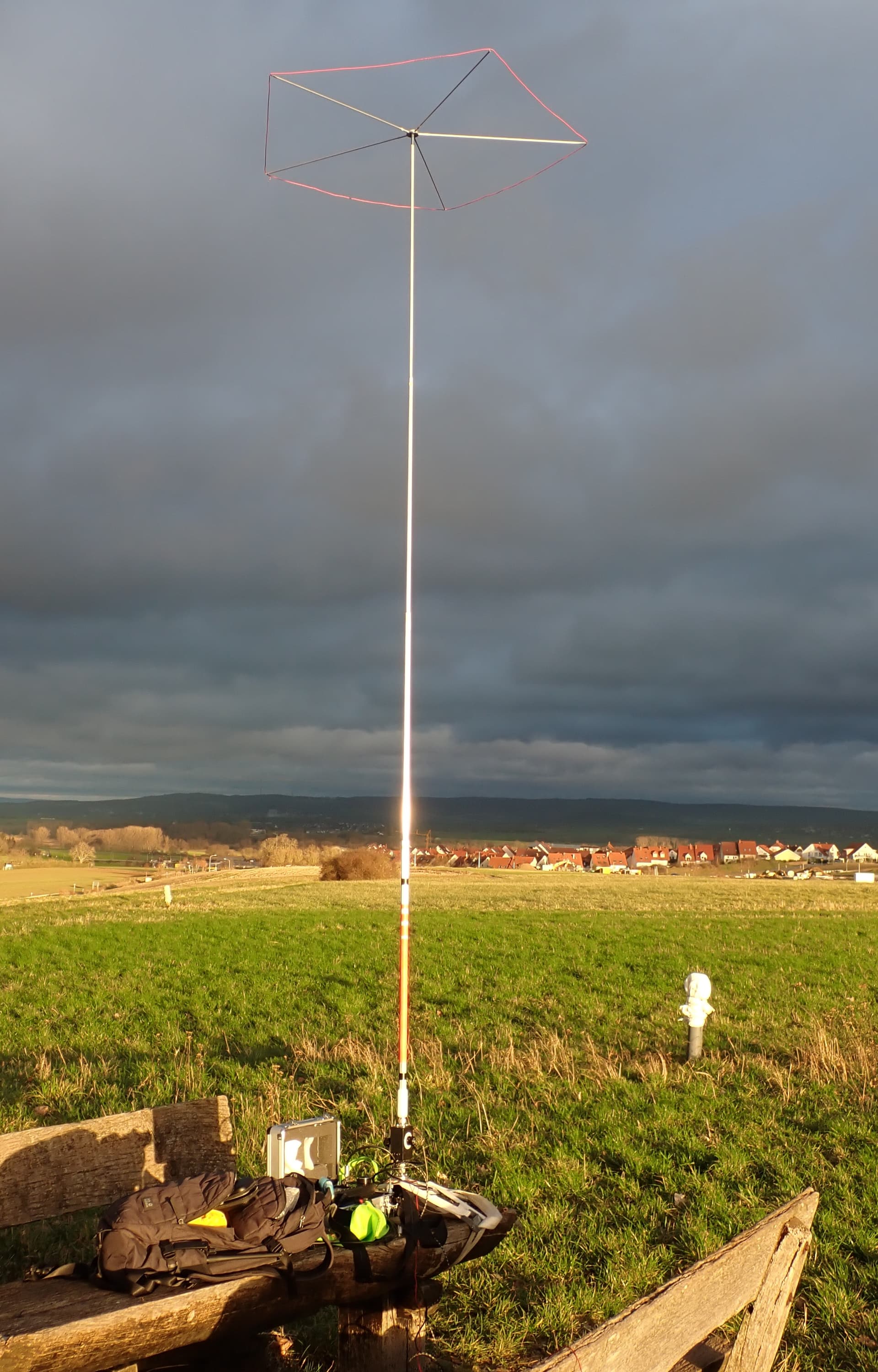
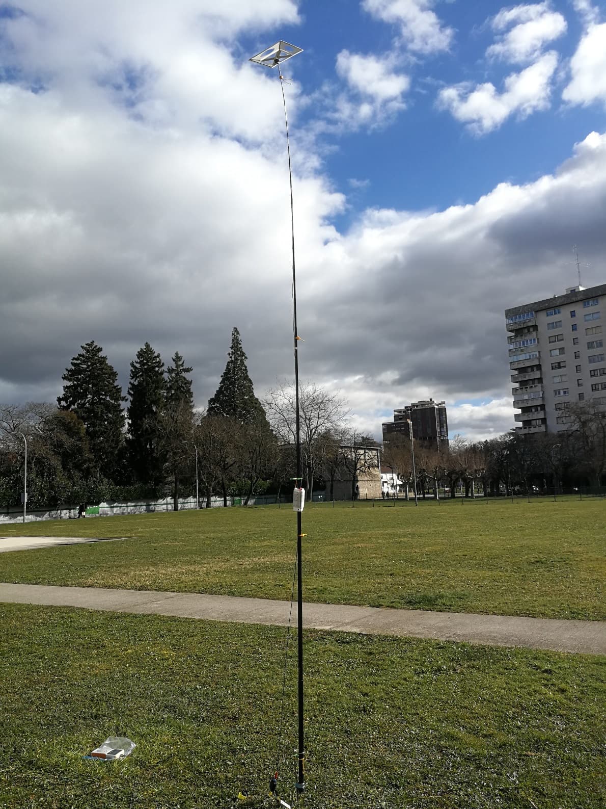
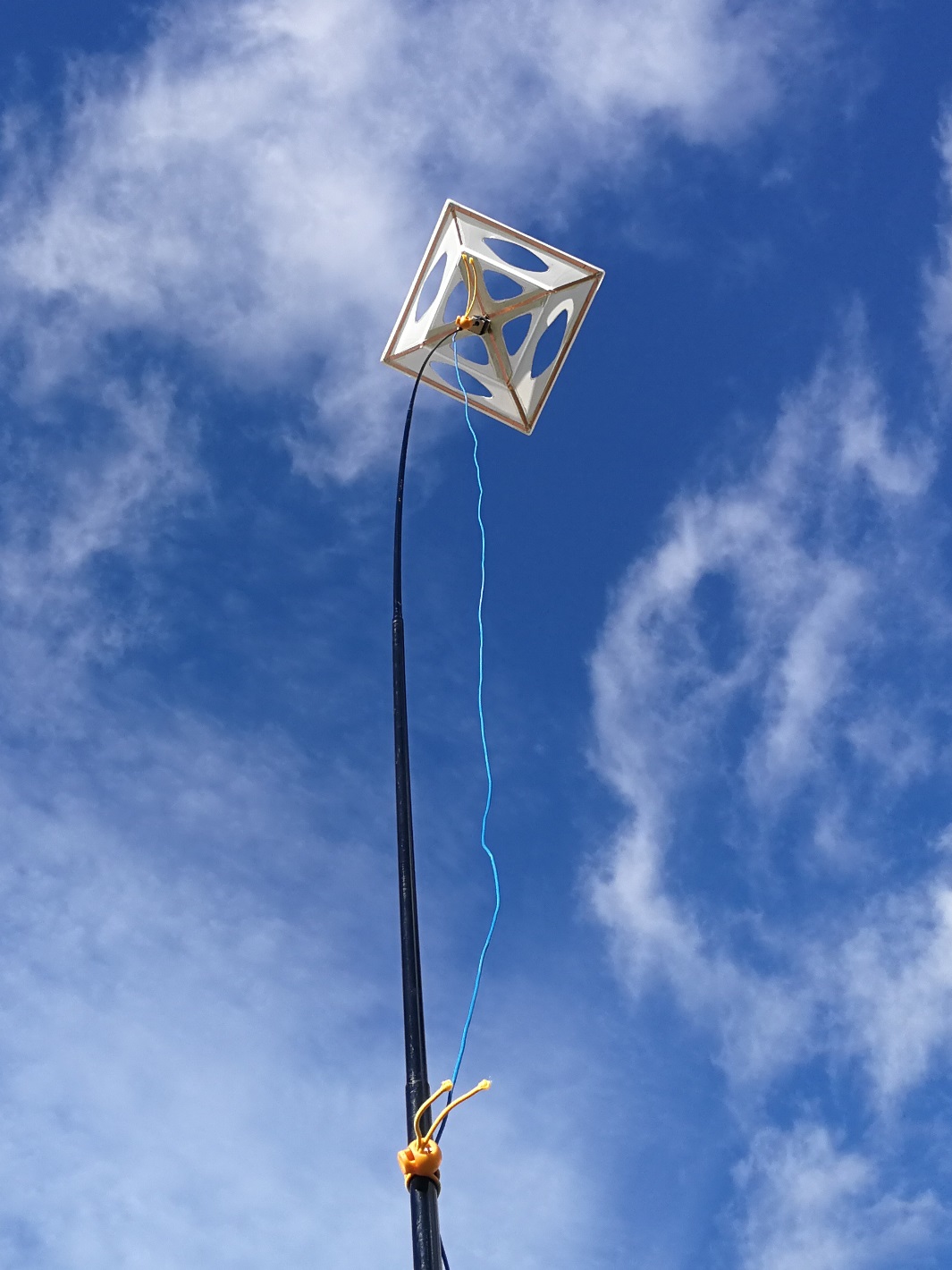
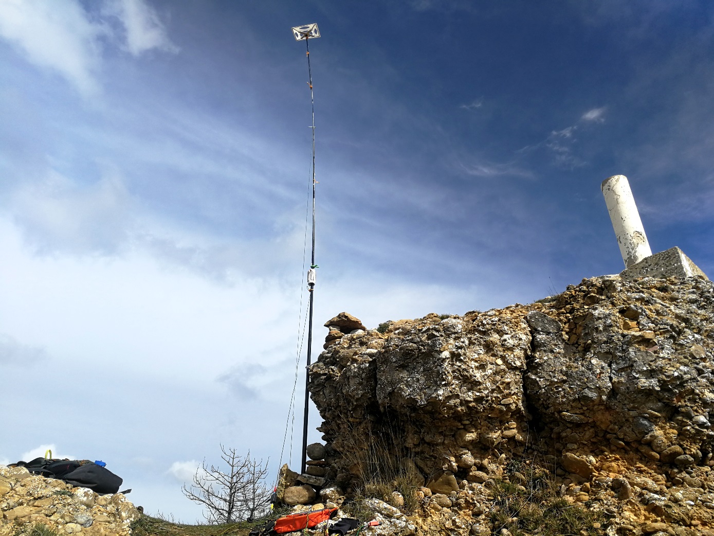
When looking it up in the air it is a fashion device! It definitively resembles a flying saucer. See the whole assembled antenna in a local park for testing:
SOTA testing
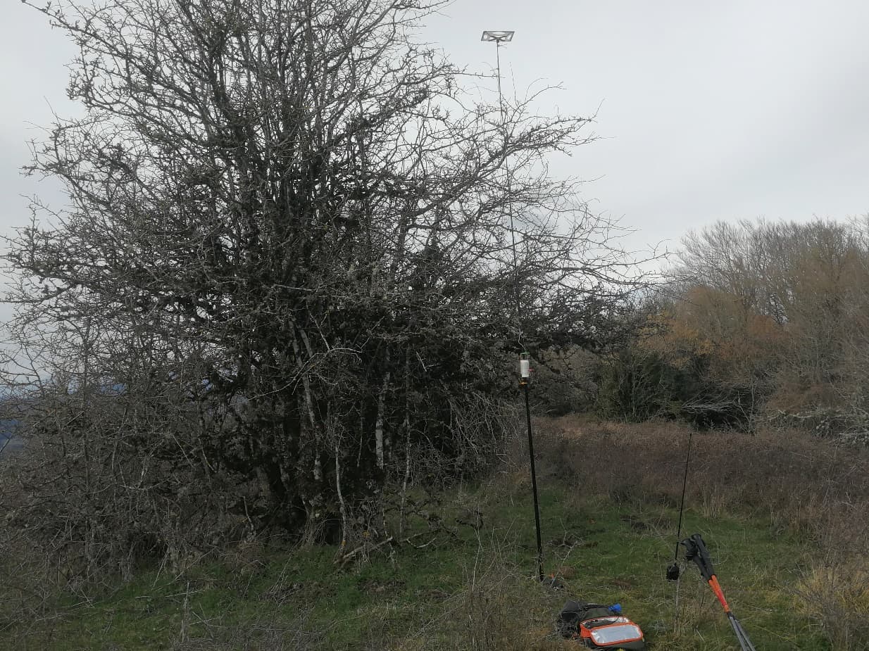
I had a previous fail of this antenna as I missed the fishpole while climbing up to a summit, but I succesfully tested the antenna deploying it over a bush (details here).
I had to wait for a proper weather to test the complete v.2 antenna a few weeks later.
Activation date: Feb 28th & Mar 1st
Summits: EA2/NV-095 & EA2/NV-097
Testing gear: FX-4CR rig , 3 21700 LiIon cells.
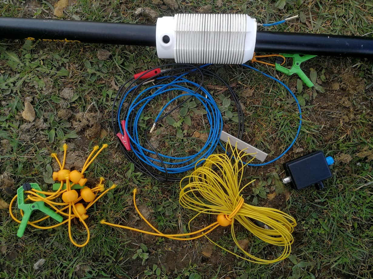
Antenna:
- Radials: 4 x 2,5 m
- 2 m of RG-174 with a common mode choke (14 turns FT114-43)
- Connector block, with an 8 turns choke over 2 FT82-43 toroids
- Bottom wire: 1,5 meter, ends in a crocodrile clip for the coil
- Center coil: 26 uHenry coil on a 62 mm diameter former
- Top wire: 2,3 meter, with a middle link to shorten it for 18 & 21 MHz
- UFO Cap hat
Setting the antenna & On-air tests
I was quite pleased to see I had reduced my setting time with this vertical. Stretching out the radials and raising the vertical was easy and fast. I had to hang the cap hat out of the rucksack during the climb, to avoid damaging it.
See pictures taken in both summits:

I verified the settings of the coil were stable, similar to the ones required back in my town. Changing bands was really done in a breeze, so I easily jumped to chase some S2S effortless.
Here a useful setting data:
Resonance bypassed coil, without Cap hat: 16,5 MHz
Resonance bypassed coil, with Cap hat on: 15 MHz
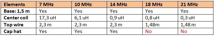
I ran the antenna in all possible bands, 7, 10, 14, 18 & 21 MHz. I felt the antenna was a real performer, both RX and TX from 10 MHz up.
7 MHz, as expected, was attenuated but I could still grab QSO in this band.
When testing in the summit a helicopter from the local rescue service appeared flying straight to the summit. They did a couple of circles at short distance and I waved my hand to send greetings to the pilot. Were they atracted by the UFO in my antenna?
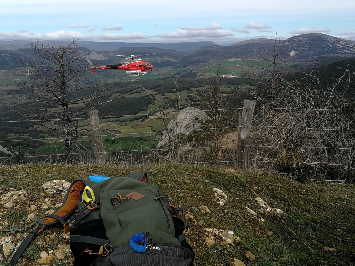
Then they moved further down and it stayed for 20 minutes doing training manoeuvers. I had to use my earbuds to get on with the activation.
Here some results & QSO maps of the two days:
Activation EA2/NV-095, 73 QSO, 9 S2S / Activation EA2/NV-097, 36 QSO, 10 S2S. My feeling was I logged similar frequent chasers as in any other normal activation with my EFHW antenna.
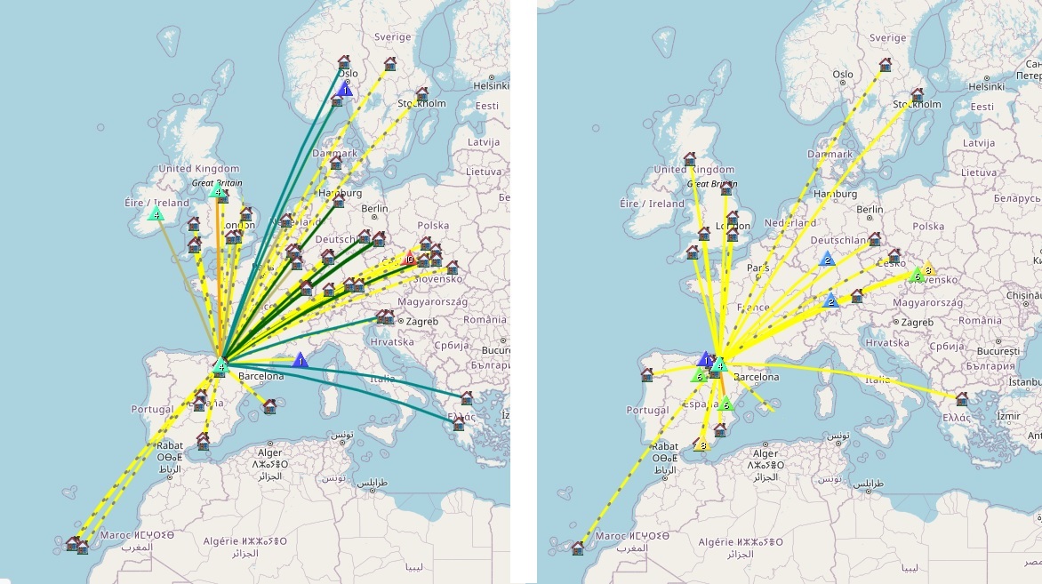
RBN Spots
I checked RBN spots back home and they meet the QSO map I got. Some info about the spots (bear in mind I didn’t spend the same time Cqing in all these bands, this is just another relative data).
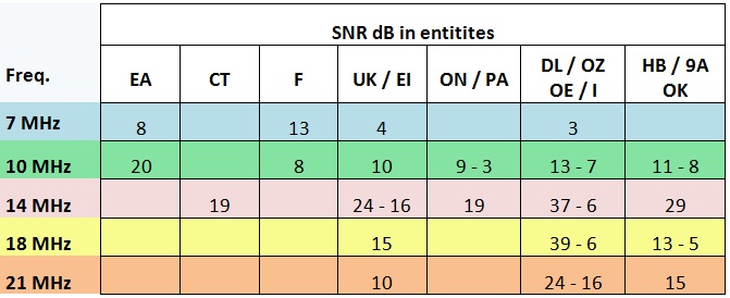
As expected, 7 MHz shows lower SNR dB & distances, although I run few minutes.
10 MHz shows better numbers, but smaller compared to 14 MHz. 18 and 21 MHz shows a skip distance in nearer countries.
In general, only 7 MHz shows a clear penalty for the signals, being the rest acceptable (10 MHz) and good (higher than 10 MHz).
Future development
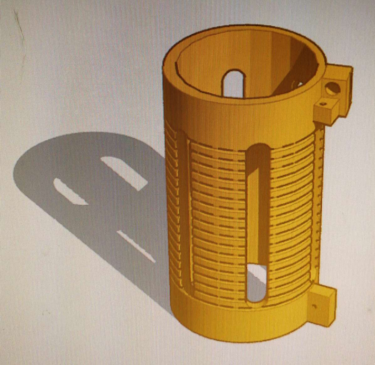
A) I plan to build a smaller and lighter Center coil, as the current one is too thick and bulky.
I have already drawn a model in Tinkercad software at a 40 mm diameter. I just need to 3D print it and test again.
B) The nice UFO cap hat could be too fragile for an extensive use in the wild. Most probably I will revert to a robut brass rod type. I’ll need to draw a center support.
C) I can add to my kit another set of 4 radials so that I could deploy 8 instead of the 4 I have if I plan to use 7 MHz to improve radiation a bit.
D) Add a fiber rod to the top section of the fishpole to strengthen it and avoid too much bend on strong wind.
73 de Ignacio EA2BD