Hi Luc,
Next time can you please test without an antenna or into a dummy load (just on receive) to see if tuning your radio across 40m, you get the interference I got when testing here into a dummy load. When there is an antenna attached, I can no longer hear the interference as the band’s background noise is higher.
In your article, you said " The bad report I got from EI7JN was because I had put the ATU in AUTO mode again, and halfway each transmission it started retuning, but then stopped at a bad SWR, "*
that sounds like a similar problem to what I had during the Portable Operations Challenge with the unit tuning to a bad SWR and the power output dropping.
I did need to make two changes to the configuration bytes in the software, one for the display I chose to use and one to reduce the minimum power for tuning from the default 5 watts to 1 watt. I might also make one other change which is to the swr for auto tuning. As standard it will auto tune if the swr drops below 1.6 and on one band the swr was around that value. Whilst talking I found the tuner going into retune mode and then getting confused as the power was going up and down with my speech. You can of course take it out of auto mode but I had not done so! The leads for the bypass and auto buttons have to be soldered on to two small pads on the underside of the board (with the version I received) which were not very well labelled.
Thanks for this Andy, you obviously chose a different search term that I in Google.
The first part about changing the trigger level to adjust SWR from 5w down to 1w might be of interest for Luc if he hasn’t already done it.
For me, the second part is more of interest. I suspect I will need to add the extra buttons/switches.
To you Ron, I don’t have the USB chargeable internal battery version, mine needs 12v on the rear socket, so I don’t think I have the noisy regulator (which I presume is actually an inverter to take the 5v battery up to 12v).
I wonder if there is actually a description somewhere of what the one button (marked tune) on my unit actually does? Not that a long press has a different effect to a short press or whatever - off to search the web again.
Ed.
UPDATE: Found the manual and circuit diagram here:
There’s a 5V regulator on the board to take 12V to 5V for the CPU. Some 7805’s can oscillate if not decoupled correctly. We’re talking cheap and Chinese here so there’s no warranty it’s a decent 7805, N7DDC may have used Tier1 manufacturers device’s which works fine with the decoupling he provided.
As Luc’s does it, probably the brand of 7805 is fussy and a few extra caps may work wonders. Or not.
Ed @DD5LP,
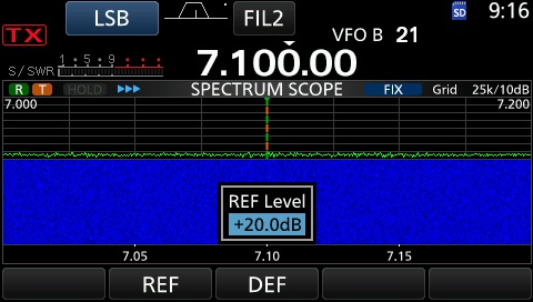
I did a quick test on dummyload, no noise whatsoever here (only checked on 40m).
See IC7300 screenshot, that is with PREAMP ON, and REF level cranked up to +20dB (to see any noise at all).
Tuning over the band, I hear a very weak ‘birdie’ on 7104.5, but that one is also there without the tuner being powered.
The regulator in the tuner is a 78L05, so the small transistor package.
If you could open the tuner and add the button to ground the pad labeled RB1, you could switch on and off the AUTO mode. Even just shorting that pad once to ground should help, since the last mode is saved in EEPROM. Then no need to re-program.
But make sure not to blow up the PIC … (see somewhere higher in this thread).
@GM4LLD
Tnx for Googling the info Andy, I know I had read that somewhere, but had forgotten if it was in the manual or on some website … hi.
Next problem is how to program this thing, I don’t have a PicKit3, but there seem to be solutions with an Arduino UNO used as a programmer.
Has anyone done it that way ? All info welcome.
To tell the truth, I’m not so bothered about the birdies - as I can’t hear them when an antenna rather than a dummy load is attached but the random re(de) tuning is a pain, so I will most likely look into adding the auto-disable button.
A very interesting thread. I’m wondering about the potential to use one of these as a remote AATU. How “auto” is the auto mode - can you just rely on the RF sensing and not need to press any buttons? Specifically I’m thinking of putting one at the feedpoint of a fan dipole in my loft and feed it 12V via bias tees so that I only have to run a single coax. I’m happy to tinker and it’s a lot cheaper than commercial remote ATUs.
I think that should work Dave, as once it has measured and stored the values for the antenna, it should simply use those settings. Being in the loft, nothing is going to change, is it?
Actually, why not simply make up a matching network to match the impedance consisting of capacitors and indicators and leave that there at the feed-point, no ATU needed. To find what you need to match to (from is the 50-ohm coax and rig) put an antenna analyser (borrow from a mate or your local radio club if you don’t have one yourself) on the feed point and note down the readings. There are on-line sites that will give you the circuit you need to build - maximum of three or four components and you’ve done what the ATU would be doing.
Lovely- thank you, Ed. I’ll likely give one a punt soon and see how I get on.
Unless I’ve missed a seriously big point, the “L/C network at feedpoint” idea is only going to be good for one frequency, while I’m thinking multi-band. My trusty MFJ-259 Antenna Analyser is primed and ready to go, although my recently aquired NanoVNA V2 is itching for its first proper job!
That calculator is a very handy thing to know about - thanks for the link!
OOps - yes correct - you’d need one L/C network for each band the antenna covers - I wonder if that’s possible to build into a fan-dipole, I suspect not. So an ATU makes sense then.
Another thought is to try the networks (switchable) at the bottom end of the feeder (whether that be coax or ladder-line) but the ATU in the loft would seem to be the best solution - as long as you throw over 5 watts of signal at it, it should re-tune if it needs to and as I said before, it’ll simply switch to its pre-recorded value in the majority of cases.
I just took delivery of a prebuilt one and confirm the RFI noise is present on < 14Mhz bands. Very likely from the IC2 OLED lines from experience building uSDX. IC@ is notoriously noisy. Im going to try disconnecting the OLED screen to see ion the noise drops. (2E0WWV)
It seems like there is a QRP version under development: ATU-10
Sounds like it should handle 10W and uses latching relays.
Apart of the smaller size, I also like that it will work with a 3.7 Li-Ion cell that can be charged over an integrated USB-C socket. It also integrates a built in programmer.
If put in a water resistant case, I think it ticks all my boxes…
For the IC-705 owners, David will even create a corresponding version.
Wherever I find I have a noisy power brick - it gets permanently purged through the use of a small sledgehammer on it. I’ve put them aside in the past then grabbed a noisy one when I’ve needed a PSU months later only to realise I have bad noise again! The sledgehammer approach solves that PSU threat once and for all!
73 Ed.
I bought one of these ready made from an e-bay UK based company. It doesn’t appear to work.
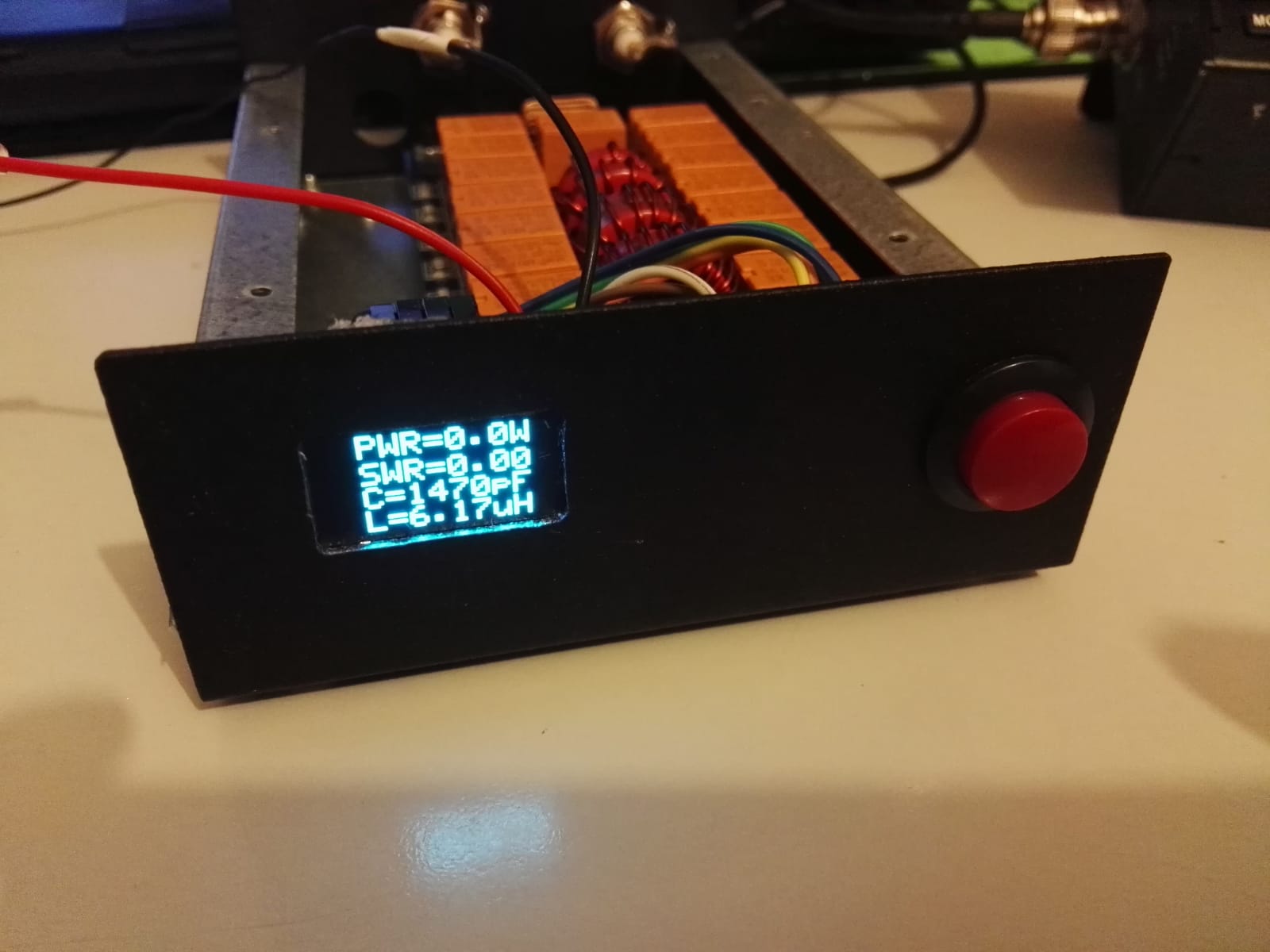
The screen comes on - it shows thePWR , SWR effeciency etc., BUT:- pressing the ‘tune’ button results in no ‘tune’ and or ‘reset’ option like I’ve seen on the videos on-line. It shows the terribly poor SWR 5: effeciency of 60% or worse along with the power, efficiency % etc., but it won’t tune up. This is on a dipole fed by coax…
Noticing that some comments here and elsewhere say it won’t tune on less than 10 watts I tried that and a little more. It still doesn’t give me the option to "tune’/reset and the SWR meter figures don’t move or change.
In short it appears to correctly show the power I’m using, the SWR reading, the effeciency % etc., but doesn’t look like it wants to tune.
Have you got the in and out swapped?
Have you checked the leads connecting it to the transmitter?
Is the SWR it reports correct?
Does the tune button feel OK?