The only good thing I recall about 10-Base-2 was when we removed it from the defence contractorI was working at and we had miles and miles of RG58 patch leads with BNCs each end. There was the usual nonsense that it was from the secure network and had been exposed to “secure” files passing over it then it could not be thrown away/scrapped but had to be destroyed. Sadly yes, the security jobsworth thought that you could at some point in the future recover the 1’s and 0’s that had travelled over the cables! I volunteered to remove it out of our lab/office and dumped it behind the bike sheds then proceeded to fill the boot of the car on successive days and took it all home. I was selling 1,2,5 & 10m BNC RG58 patch leads at rallies for some time after that. Nice little earner. The cables are still probably recorded as missing on the security register!
Andrew VK3ARR,
I suggest that calculation of the SWR is based on an assumption that a 75 ohm connector represents a 75 ohm load. If in fact it is just a short impedance bump in a 50 ohm line, the impedance presented depends on the wavelength, the physical and electrical length of the mismatch etc.
eg. 2 cm of 75 ohm impedance followed by 10m of 50 ohm line would cause a slight mismatch, I think detectable only by a TDR test. The change of impedance for HF where 2 cm is a minute fraction of a wavelength even on 10m, (2/10000 = 0.0002 wavelength) is unmeasurable by any test equipment I have. In a section of feedline that has a different impedance to the rest, an impedance transformation commences, the ultimate being a quarter wave line. Until the length of 75 ohm section is a quarter wave, the impedance becomes reactive with a rising impedance, reaching 100 ohm at the quarter wave point, etc.
A worse mismatch would be created by lowering the antenna by 1 metre without retuning the ATU.
Inside the ATU, connections are made with bare wires or traces on PCBs, without any indication of 50 ohm stripline procedures, as they are unnecessary, due to the shortness of the connections with respect to the wavelength. Any concerns about the impedance of the connectors, both in and out of the ATU, are therefore misplaced, in my view.
An example is given by a Johnson matchbox, a well respected balanced tuner from the tube era, where the output connectors are large wing nuts on insulated bolts. The spacing suggests an expected impedance of 1000 ohms, so does it work for a 300 or 50 ohm load, yes… because any impedance change due to the spacing not matching the feedline is adjusted when you change the link tuning or the tuning of the output circuit. And of course the impedance of the input connector is ? ohms as it is a SO239. Inside the tuner, there is a bare wire leading to the link coil. The impedance of that bare wire, being spaced several inches (these were made in the US so all measurements have to be in UK standard units) would be hundreds of ohms. But it works fine!
73 Andrew VK1DA/VK2UH
Yes those connectors are 50 Ohm, and actually fit much better than some Chinese “plated zamac” connectors …
@DD5LP
Mine came with MANUAL as default setting, and I’m not sure if you can change that on the fly with the TUNE button (you can change an EEPROM parameter to default it to AUTO I believe).
The choice of AUTO vs. MANUAL depends on your power.
With a 5W or 10W rig, AUTO is no problem, it will retune anytime you change bands or SWR is above a certain limit (also a parameter in EEPROM).
But when using a 100W rig, I wouldn’t leave it in AUTO mode, imagine what will happen if it suddenly retunes with 100W on those relays … so then MANUAL is advised.
@VK3AFW
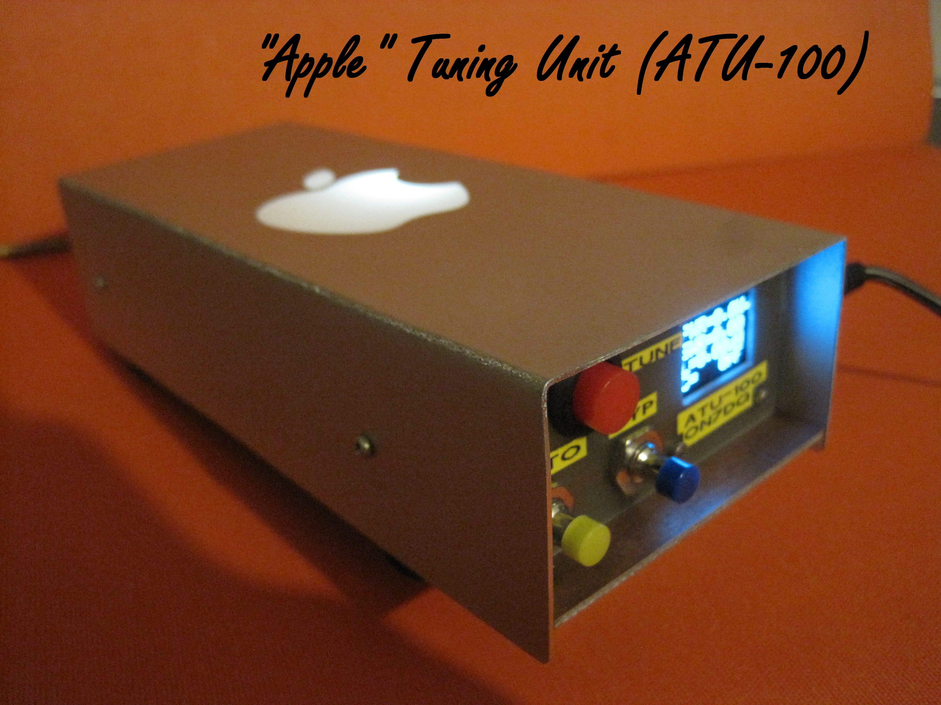
I could make a cover from PCB material, but I just like the idea of telling people I have a 30$ ATU, with the cover of a 3000$ computer … haha.
And I sure will try to reuse that Apple logo ! 
Luc ON7DQ
Nice.
73 Ron
Unfortunately, I have to report that this ATU causes RFI! Running off battery power into a dummy load on 40m and I’m getting a “Chuff” “Chuff” “Chuff” at different places in the band. Turn off the ATU and the RFI goes away.
Are other people hearing this with their ATU-100 units?
73 Ed.
And I thought being chuffed was good! 
I’ve not noticed it but need to try a low noise dummy antenna.
73
Ron
I wonder if it might go away if I can turn off the auto SWR checking but I haven’t found how to do that yet and this is happening on receive not transmit, so I would have though the ATU should only be checking while it sees RF from the transceiver. If I press the “Tune” button, while it is pressed the noises are no longer there.
73 Ed.
Try the tuner on a separate PSU to see if the noise is on the power rails. If it is, add some better decoupling to the tuner’s rails.
Hi Andy, it’s running off a battery, I don’t think there will be noise on the power lines, but I can try it.
It would be good to know if anyone else with an ATU-100 is seeing the same thing or it’s just mine (bought fully built), that is faulty.
73 Ed.
Hi Ed,
Nothing found on mine. Sounds like the uP checking to see if there is RF and if it needs to retune. There isn’t a tx line AFAIK so it relies on RF sensing or a button push.
What to do depends on if it is direct radiation from the uP into the RF side of the tuner or as Andy suggests conducted along the power cable.
Good luck.
73
Ron
VK3AFW
Hi Ron,
But would it be checking constantly while in receive mode? It does sound like microcontroller noise, so you could be right. I hope I don’t have to reprogram the EEPROM (or whatever it is using for storing its configuration). When the only button on the unit (Tune) is pressed, the noise stops but that’s likely that the coax from the rig is cut off while in tune mode.
73 Ed.
I’m suggesting this based on the 9 years I spent as the engineer responsible for getting products through CE marking. Until you measure it or discount it you don’t know how the noise is being coupled into the radio.
The description sounds very much like a CPU waking up, running code and then going to sleep again and based on the above, I’d check very carefully all the decoupling components are fitted correctly.
OK, sorry misunderstanding - you are suggesting not that my power lines are noisy, rather that the ATU is putting noise back to the radio possibly on the power lines!
I can check that it’s not coming back to the radio via the common power source, by running the ATU off an extra Independent battery. Test done - noise is still there, so it’s putting the interference to the radio down the coax or purely emitting it in the close area - something that an ATU certainly shouldn’t do!
Hopefully with a strong signal, I wont hear this noise - I have only heard it with a dummy load connected so far. I wasn’t looking for it, the last time I had a real antenna on the unit.
Thanks & 73 Ed.
Ed,
You cannot hear what the beast is doing when you are transmitting. Your receiver is silenced. It does not know you are in receive mode nor does it know when you are going to press the PTT. So it checks. Regularly. If RF the SWR is? Tune or keep checking.
Whether when on a summit the noise will smother the spuglie only a field test can say.
Good luck
73
Ron
VK3AFW
Just a quick update - after highlighting this device to everyone, I feel it’s only fair to also highlight the fact that during my mediocre attempt at getting contacts in the Portable Operations Challenge on Sunday, the tuner, after having tuned the antenna fine and working with it at 20 watts for half an hour, it suddenly decided to re-tune the antenna dropping my forward power to 2 watts. A quick press of the only button on my unit “Tune” and it fixed itself for another 15 minutes when it happened again. In this time the antenna did not change in any way and neither did the coax cables.
One positive I suppose was that although the MCU noise was still there on 40m, it was low enough not to cause any issues.
Ed.
That’s what you want to believe. You may well have a a break in your coax starting… most of the time it’s fine but just now and then the continuity fails. I’ve seen this on my RG174 runs a few times. Once was sufficient to take out the 817 PA ![]()
But as you also have this noise that nobody else is reporting then maybe… you have a faulty unit. Possibly not only is it radiating RF but could be picking it up your own transmissions. Faulty decoupling capacitor? Dry joint? Poor case contact? It probably just needs some careful observations when used to see if the problem can be isolated and resolved.
Hi Ed,
This is a long shot but was you antenna moving in the wind and lifting the see enough for the unit to do a retune? Odd that it got it wrong and needed to be told to do it again.
Another long shot. RF from another nearby transmitter. When operating in proximity to other stations I’ve had my ATU sense RF from those stations and interpret it as reflected power. Needless to say it made a right mess of tuning up. We were operating with antennas within 30 m and not on the same band. 100 W transmissions.
More investigation required Ed I suspect.
73
Ron
VK3AFW
Hi Andy, Hi Ron.
Firstly to Andy - coax problem is possible I suppose although no obvious damage on the RG58 is to be seen.
In response to Ron - it was a calm, dry morning - no wind - the antenna in use was a loaded HF whip on a mag mount on the car roof. I don’t see any likelihood of it moving to cause this issue.
Other local RF source - no - thankfully no one for miles around!
Which brings us back to the “faulty unit” option - and I paid specifically to get the built & tested model not the kit. As it’s bought from a China Warehouse, I suspect I will not get any support from them, they simply sell whatever they can get from their wholesaler, so one minute it’s an ATU, the next item could be a loo brush or womens make-up!
One long shot from me is to perhaps locate the ATU further away from the rig as this re-tune is happening, if I remember correctly, while I am on transmit (which I know is logical but maybe it’s being triggered by RF ingres rather than a bad VSWR?).
More tests to be done. In fact, once I have my portable amplifier working again it may be easier to make the problem re-occur.
As you say Ron, more investigation needed.
73 Ed.
Hi Folks,
Yesterday I finally could test the ATU-100 in an outdoor situation (local park).
Average current was some 30 to 40 mA.
I did not hear the noise that was reported by Ed, @DD5LP.
Read the full report and some preliminary conclusions on my blog:
73,
Luc, ON7DQ