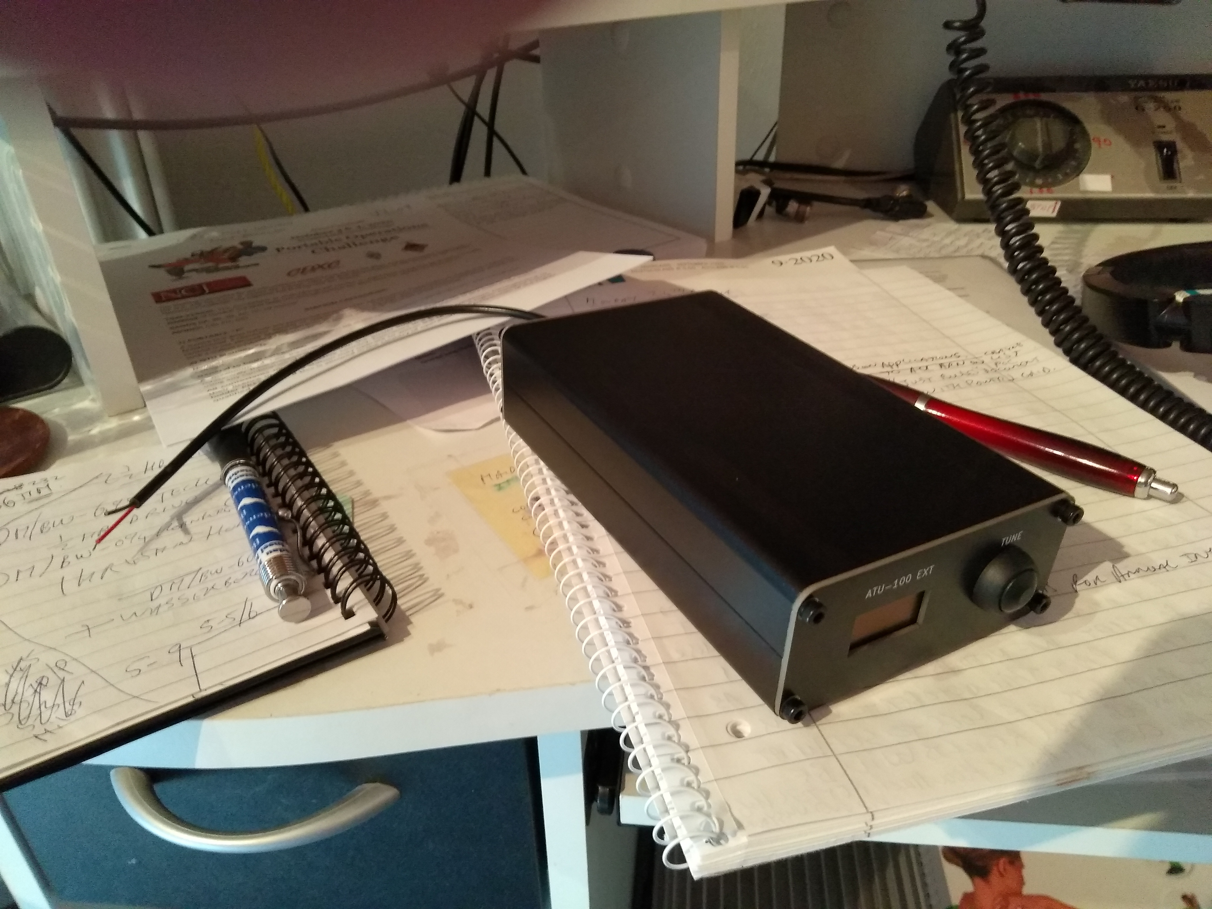
I built an ATU100 then after exhaustive testing cased same.
its specification claims:-
*Supply voltage of 10-15V dc,
PCB has a 5v regulator for both the switchcing transistors relays and PIC processor. My unit works from 8-14Vdc, my PSU max output is 14V
*Maximum current consumption 400mA.
During Tune mode all relays can be used, but not all are simulataneously used,
In test mode all relay driver devices (2n2002) are turned on, respective relays are energised. 15 Off relays plus 2n2002 devices and respective PIC outputs which is 400mA
-
Maximum working throughput of the standard 7x7 variant is 100W
the relay contacts are only rated at 1.3A, therefore before entering tune mode the recommended power source is less than 10W. Once a tuned solution is found, the power can then be icreased to 100W.
There are pads on the underside of PCB to wire connection to transceiver for tune initiate and from ATU100 to transceiver to initiate power reduction, provided the transceiver has these options.
-
Maximum possible measured power 150W
I had an input of 118W through the unit, with no obvious signs of stress or damage, though with respect to relay contacts, 100W would be the limit.
*minimum power requoired to start tuning 5W
5w is default. This can be changed using a software / hardware option
it can go less than 5W, however the sense coil will require rewinding, there are details on internet showing how this is done.
- Minimum possible measured power 0.1W. True
*Accuracy of power measurement 10%
My unit tracks a Bird 4413 with both 5 / 50 / 100W elements used
-
Typical consumtion 150 - 200mA
Once tuned solution is found the current draw is low
-
Frequency range 3 - 54Mz
My unit has been proven to work between 3.5 to 29MHz, not tried on 6m.
Only tried with dummy load and off resonance dipoles (purposely lengthened and shortened dipole elements to give high SWR of 4:1)
Unit found a tuned solution all bands 80-10m with exception of 30m had to reset and retry Tuned mode. Equipment Elecraft K2/100
Unit is not easy to build if you are not used to SMD components ranging in size from 1206 to 0603. Also uses air coils, single and double toroids.
Relays are made in Hong Kong, no equivalent in size or pinout, so expect usual delays for these. Relays are HK1400’s pinout does not conform to usual standards.
Most SMD’s are on rear of PCB, I was encasing mine, so soldered M2 nuts on bottom 4 pads for same on PCB, this protects components on underside from damage.
Relays are last to be installed. They are very susceptable to heat damage.
Also take care winding toroids they will only mount in PCB through holes if wound the correct way. I had to rewind all mine.
If your PIC is not programmed, then you will need a PICKIT 2 or 3 to program same, also need the PICKIT to change any parameters that includes display type and OLED size.
If you choose Autotune mode, then the power throughput must be less than 10W
In power down, the unit defaults to Bypass mode