Be careful of you are thinking buy it. The tuner don’t start to work with <5 or 10 watts. It’s needed reprogram it with pickit 3 to run under 5 watts. I have one but don’t work with my Yaesu 818 by the low power. My pickit 3 don’t don’t work fine on windows 10… And it’s Impossible to reprogram it by myself.
It’s fast, light and low power consuming but bad with minus 5 watts and… And all qrp transceiver have swr protect that reduce the power under 5 watts…before matching the swr
I bought one from Ebay last month as a kit, no issue building it, it didn’t come with any instructions at all, but they are all available online on the designers page.
because at the time it was the cheapest I could find and I was in no rush for it, but there are many more on Ebay from both the UK and China.
If you are planning to use it with low power, then the designer suggests that you wind the transformer in the bridge with a different number of turns, this is explained on his web page too.
I did mine exactly as he said, plus there are a couple of changes that need to be made to the PIC EEprom I also did it using a Pickit 2 under Windows 10 (1804) and had no issue whatsoever, in fact I do all my PIC programming using the same Pickit 2 and Windows 10 and have never had any issue with it.
I used the standalone Pickit 2 software though on the Windows 10 laptop, not Mplab, but the Pickit 2 works with Mplab too on my desktop under Windows 10.
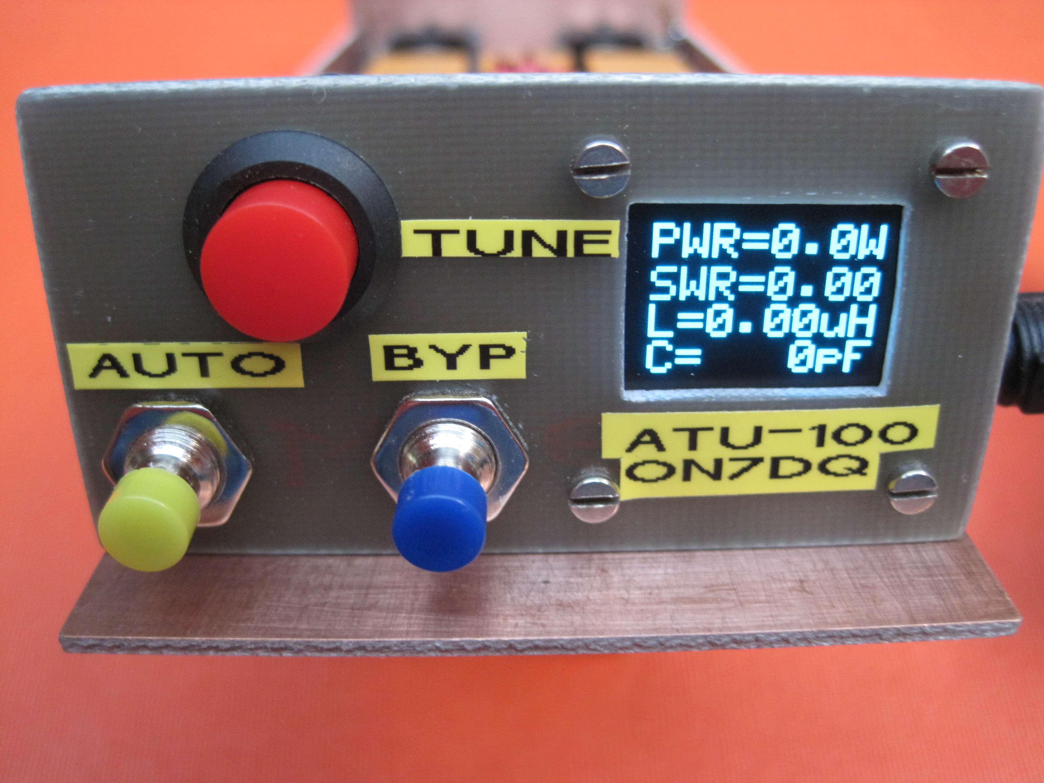
The ATU seems to work very well, I also put the small OLED display on mine, it’s ok but a bit hard to read in daylight particularly bright sunlight, the text is quite small too for my aging eyes!
Only issue i’ve seen was when I tried to tune a 9’ military whip antenna, it wouldn’t tune below 10MHz, not surprising really as there isn’t enough inductance / capacitance, but a wire longer than 30’ would tune on all bands with a reasonable counterpoise attached.
The RF power meter on the OLED seems to be reasonably accurate too, at least from 1w to 25w it does which is all I would really trust the capacitors for, after doing the changes I mentioned above, mine will always tune with a solid carrier from 2w upwards.
All in all I can’t fault it for the price, it did take a while to arrive from China though.
Hi Tony,
I also bought a kit but have not yet started to assemble it. Configuring the transformer for lower power seems like a neat idea. I have one of the quick tune dongles for the 817, so it produces 2 watts of AM when triggered by the double click on the mike. Ideal for ATU retuning.
I plan to get a SMD-familiar friend to solder in the CPU chip, the pin spacing is less than my thinnest soldering iron tip. Perhaps it is best done with solder paste and a hot air gun? What would you recommend an inexperienced SMD assembler to do?
Great to see the link to the designer’s site.
Hi Andrew,
Mine is finished and working. It won’t tune with a 10 w rig. It tunes with a 100 W rig set to 10 W. Took me a moment or two to figure out why.
Needs a mod for my board. Others may be OK.
My biggest problem was mounting the display. I did not have thin enough bolts in my box so had to ream out the holes. I found I can no longer file a nice square opening in a case. It’s a bit off
Well, I managed to blow up the PIC in mine, I was putting the wires on the back of the PCB to attach the two extra switches, instead of soldering wires to the through holes which go back to the PIC and ground, I put the ground wire on raw +12v, so first time I pressed the push button switch the PIC died, i’ve been back to Specsavers since so it will not happen again
The way I replaced the PIC was to cut down the legs where they go into the plastic of the IC, I do this on each side with a scalpel or new Stanley blade, once they are all cut, the plastic of the IC will come off leaving all the legs standing up still soldered to the PCB, it is dead easy then to unsolder each leg carefully whilst holding it with SMD tweezers.
Once they are all off, clean the PCB with some solder wick and Isopropyl alchohol, and put some SMD rework flux on the pads.
Then, making sure the PIC is the correct way around, drop it onto the pads and get it as close to aligned as you can, a magnifier helps massively.
Once it looks ok, solder one of the corner legs down using the thinnest solder you can find, and a good iron, I use a Metcal iron with a needle tip.
Check again that the IC is the correct way around, and the alignment is good, then if you want put some more rework flux on the IC and PCB.
Then it’s just a matter of going along the legs soldering them in, again use really fine solder, and take your time.
If you get a blob between pins, don’t be tempted to use a solder sucker to remove it, the jolt it makes when pressed will cause either the legs to bend or the track to come away from the PCB, use solder wick to remove the excess solder that forms the blob.
Once they are all soldered, clean the PCB with more Isopropyl and check with a magnifier for any shors between the pins and you should be good to go.
SMD construction is quite easy and nothing to be worried about just take your time and don’t use too much solder, using leaded solder is actually easier than lead free as it flows better.
Bad luck about the error. At least you were able to recover. I presume you had to program the chip yourself. I think the Chinese board is tinned with lead solder. Using lead solder will therefore work best.
I never could do so to start with never mind getting older! OK, so you are hiding the less than perfect display mounting but it still looks like it will be a nice job you’ve done Ron.
Just received my package, it arrived in 11 days wow!
Well packed in a plastic box, then bubble plastic around it, then in a bubble envelope.
This is what was in the box.
All SMD’s soldered, PIC should be programmed, OLED display included.
I paid 27.84€ on Ali Express, free shipping.
Now find some time to assemble it … I want to put it in one box with a Chinese 50W amplifier.
Luc ON7DQ
Yes, I had to reprogram the replacement PIC, as I said, I used the Pickit 2 on my laptop running Windows 10 and the standalone Pickit 2 application, the .hex file is available on the designers github There is also the info here about the modifications for lower power use and several other things that you can customise, by simply editing the eeprom contents in the pic, again done through the Pickit 2 programmer application.
Other than the blown up PIC issue, caused by me, the ATU has been really good, as people have said, it doesn’t use latching relays, but for the price, you can’t complain.
I changed my mind about sacrificing the tuner to my 50W amp, and decided to make it a stand-alone unit, so I can use it with a QCX for a small QRP station with “autotuning”, or just use it as a digital SWR and power meter.
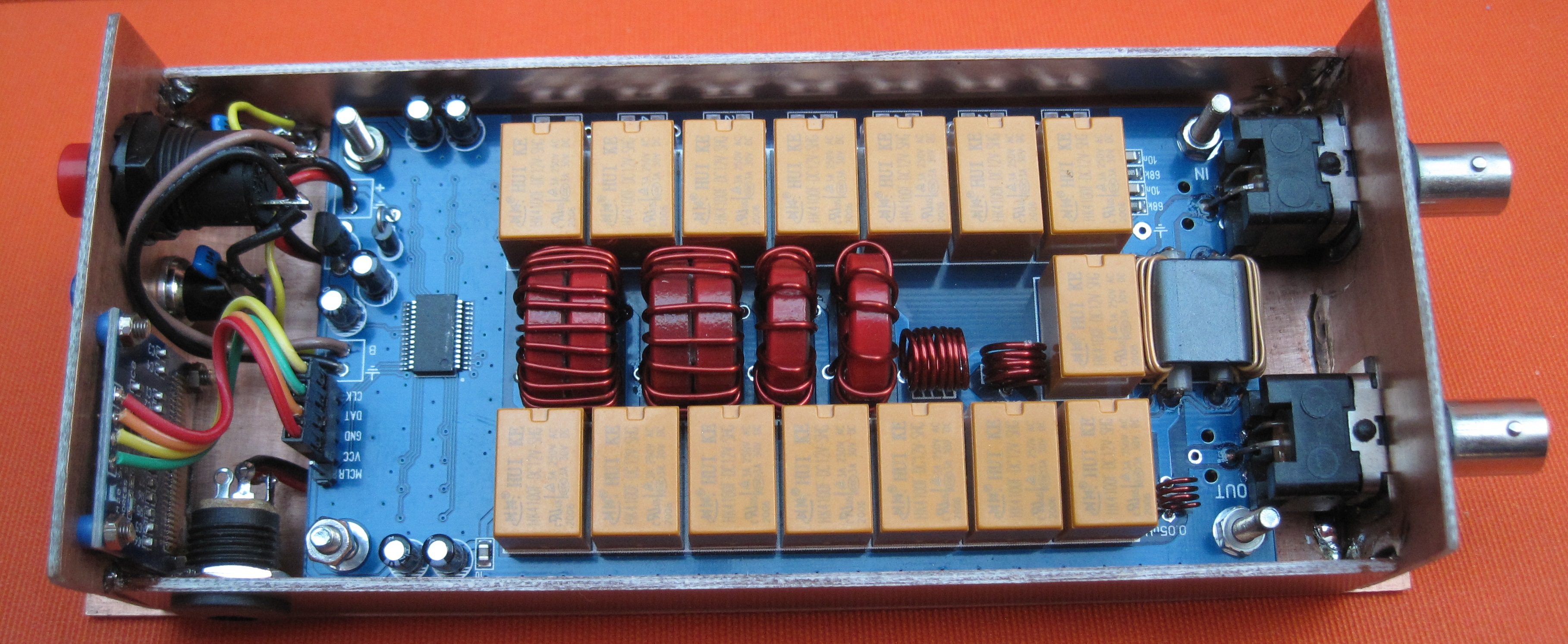
Assembly of the PCB was not so difficult. I glued the double ringcores with superglue before winding them.
Winding the tandem match (PWR/SWR sensor) needed some care and concentration.
Then I looked through all my “junk box boxes”, and none would really fit, so I started making the smallest enclosure I could come up with, from pieces of copper clad board.
I added the two small buttons for AUTO and BYPass.
I didn’t use the SMA connectors, but used two ex-Ethernet card BNC’s.
DC input is on the side, behind the display.
Many more pictures on my blog, click the link below.
Now all I have to find is a nice cover, bent in a U-shape to fit over the top.
I have a bunch of thin & light covers from Dell laptops (titanium?), even the cover of a Macbook Pro, with the Apple logo in it, wouldn’t that be nice … of course mounted with a LED backlight, maybe couple it to the RF output, so it lights up when transmitting ?
I’m not sure but I seem to remember that the computer ethernet BNC connectors were 75 Ohm not 50 Ohm? You should be able to see by looking at the size of the hole for the centre conductor, 75 Ohm ones are larger.
You have an Auto button and a Tune button. I thought the unit was auto (i.e. RF triggered) by default. Does the auto button turn than on and off so that the Tune button has to be pressed?
“ThinNet” ethernet cable was 50 ohm, and used 50 ohm BNCs, so I think the cards would have used 50 ohm connectors too. Having said that, the card connection was a high impedance tap into the 50 ohm line, so the connector could have been almost anything I installed many kilometres of it back in the day. And some “propper” thick ethernet too…
Or, to put it another way, “smaller” (eg the diameter of the centre pin, just as for a given sleeve diameter, 75 ohm coax has a smaller diameter centre conductor than 50 ohm). The difference is so slight that good quality connectors of either type are compatible, though you wouldn’t mix them in critical applications.
I think it was sometimes called “Cheapernet” when comparisons were made with RJ45 cabling of the later, higher speed CAT options.
In any case, great that it was 50 Ohm, not 75, so those connectors are OK for Amateur Radio re-use. As I said I wasn’t sure. I do remember some problems once on a thinnet installation, which came down to mixed connectors between 75 and 50 Ohm.
I think the difference is nothing to be concerned about for HF, especially on the antenna side of an atu, where the antenna impedance isn’t anything like 50 ohms, after all that’s why you use an ATU. On the radio side, the connector impedance still doesn’t matter so much. Most amateur equipment and most ATUs of all brands except Elecraft use the M or SO239 type sockets and the impedance of those connectors is not 50 ohms either.
Indeed, if my calculations are correct[*], 75 ohms into 50 ohms, or vice versa will be an SWR of 1.25, which most people would consider is acceptable and this translates to about 1% of actual loss.
I guess Andrew that you’re not quite old enough to have seen 10-Base-5 and 10-Base-2 properly deployed. Or should I say improperly deployed. It was a nightmare of unreliability. Everything would work and then you came in the next day and the networks was slow and intermittent. People spent their lives disconnecting the T pieces and cables, changing lengths of RG58, playing with terminating loads etc. Then the cables had such mass it could easily unseat PC cards from their slots if the fixing screw was installed to hold the card in place. (It was always loose or missing!)
You’re right about the VSWR being small and even for finnicky solid state radio gear it doesn’t make any real difference. But in the 10-Base-2 world, the step impedance change did have an effect that caused more reflections and ringing on the cables which increased errors etc. and lowered the noise immunity. As 10-Base-T was rolled out and people replaced hubs with switches, the improvement over 10-Base-2 became very apparent.
Oh, I wasn’t referring to 10 base 2, which I caught the tail end of. Using a drawing pin to bring the network down so exams were rescheduled, etc. But Ethernet as a layer 2 protocol on top of coax is a different beast to typical HF modulation schemes