Regarding radials, there are (at least) two types of vertical to consider:
1 A ground-plane where the base of the 1/4-wave radiator is above ground; perhaps 5 or 6ft high for a 20m GP. You might have 2 to 4 elevated radials. Make these nominally each a 1/4-wave long. Altering their slope angle, and the length of the vertical radiator, allows you to adjust the feed impedance towards 50 ohms at your desired design frequency.
2 A ground-mounted 1/4-wave vertical with the base just 2 to 3 inches above ground. The conventional wisdom for this type says: “If you have a given length of wire to make your radials, prefer more short radials over fewer long ones.” This advice is based on the idea that radial currents are more concentrated near the base of the vertical than further away.
None of this is an exact science; you’ll need to experiment. What might work best in your local park, won’t necessarily perform the same on a SOTA summit due to differing ground conditions, sloping terrain etc.
With the ground-mounted vertical you’re less likely to a get a good 50 ohm match however much you play around with the radiator and radial lengths. You can you use something called a HAIRPIN match at the base of the antenna to get close to 50 ohms into your feeder. But with only a short feeder you can probably just let the ATU in the rig do the work.
At the home QTH, I have a 30m 1/4-wave (Al tubing) GP, base at 10ft, with 2 elevated, sloping, 1/4-wave wire radials. This has been a great antenna for 15+ years. Feed impedance is around 50 ohms; I have a coil comprising 10 turns of RG-213 coax on a 4in diameter former at the feed-point to act as a choke balun.
John, if you are making it for SOTA activations then, in my opinion, ease of setup and repeatability of match are most important. That is can I put it up when wearing gloves and is it always an OK match before I need to hit the ATU button (if you have one).
From my experience, the 1/4wave GP does that best. That’s a 1/4wave vertical element and the 3x 1/4wave sloping radials at 45deg. When I used one for the 12m challenge it was always easy to setup and the match was not significantly different from hill to hill. It also gets the feed point 2m AGL off the ground and, for me, fits a 5m pole.
A 20m GP will need a 5m vertical and the feed will be 3.5m AGL and that means at least 8m pole which is big and heavy. If you lower the angle, you can lower the feed point so it all fits a 7m pole which is much more mangeable. Of course it wont be 50Ohms and you will need to adjust the lengths to get the match back.
Either 45 or whatever angle GP are simple to make, 4 bits of wire and a connector. I have plenty of old BNCs which is what I used but for QRP (<10W) a phono connector will do.
I would suggest setting up a classic 1/4wave GP in MMANA or such and seeing the figures for match etc. and then you can lower the feed and see what happens. And more radials helps but if you read on here Gavin’s GM0GAV description of his fixed 160m antenna and what he did to make all the radials work you’ll see there’s not much point for a quick-up/quick-down SOTA antenna in having more than 3 radials.
Another good omni for SOTA is a delta loop which works well when close to the ground. Simon GM4JXP and Roman DL3TU both have them for 20m.
Not really - the feedpoint impedance would drop into the mid- to high-30 ohms range, with not much else to show for it. Stick to the 3 radials which, as others have and will point out, are all you need to get a good omni pattern in azimuth, and a decently low take-off angle in elevation, plus a feed-point impedance of just over 50 ohms. You can also safely have the radials’ angle at about 30 to 35 degrees to the horizontal to save on some height, with no great change in FP impedance - good for matching up to your 50 ohm system.
As to using a delta loop, to give a decent omni azimuth pattern, it would need to be fed either at the apex (a long coax run-out!) or at the mid-point of the lower horizontal element. Good omni pattern in azimuth yes, but it’s a sky-warmer NVIS antenna in elevation - a terrible choice for DX (and the FP impedance jumps to around 200 ohms). Delta loops are decent monoband antennas if fed at either one lower corner, or at 1/4 wavelength down from the apex (which is fairly close to the corner anyway) with about 5dB side rejection and fairly low elevation take-off angle (just over 20 degrees), and in this configuration they’re vertically polarized.
Presumably the proposed antenna is for what might be considered “serious” activating and therefore needs to designed along the lines discussed. An alternative approach is to use the KISS principle and go for a simple design such as I used when activating in Portugal… a 5m travel pole with 5m of wire up the pole and 5m out along the ground in the nominal direction you expect contacts to come from, fed as a dipole. It worked for me and was extremely quick and simple to deploy, but I wouldn’t use such an arrangement for say, the Trans-Atlantic S2S events.
Of course the other thing is that what works fine on your back lawn with a brilliant SWR may not work on a rocky summit. A compromise may be required. Finding it is the key.
Add cord to the ends of the radials to keep them elevated. I have heard about the 45 degree angle thing many times over the years. I mount my 20m GP on a standard 6.7m pole so my angle is much flatter. Doesn’t seem to cause any issues.
Build it, test it, you might need to trim the radiating element - but probably not if you use thick core wire like the mil. spec green wire that SOTAbeams sell. You certainly won’t need to trim the radials!
Cheers chaps. For my 10m vertical I attached the radials to the guy ropes and will do the same for this one as well.
My normal SOTA pole is too short to keep the feed point off the floor. My other SOTA beams pole will keep the feedpoint off the floor but it is heavier.
Some work needed over the next few nights to get the setup sorted.
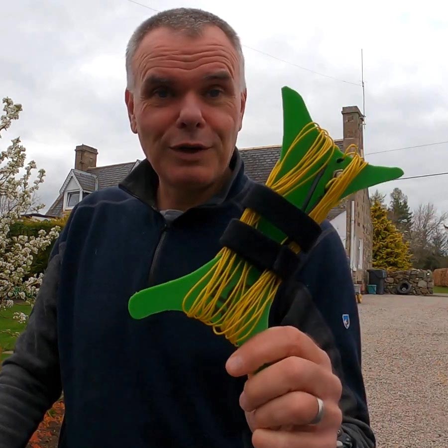
Remember also, that while more radials might work better, no matter how carefully you pack them and even if you put each radial in a separate bag , they will tangle en-route.
The graphing the time to untangle vs temperature shows a parabola with the mid/low point of untangle time being at a comfortable working conditions which then rise towards infinity as comfort levels decrease.
Time taken to untangle in seconds = (number of radials / 0.025 ) x(Temperature in C -18)^2 + 30
The time above maybe reduced by dividing the result from above by the separation distance in nearest whole light years (rounded up).
This equation only holds true in dry conditions, but the calculations become more complex when factoring in rain, which increases discomfort , but decreases friction between the radials.
Further modifications can be made by adding in the wind factor, but this also requires careful measurements of weights and surface areas of the radial wires.
And no mention of Coriolis forces, or forces induced on the wires by variations in the Earth’s magnetic field, or from particle decays originating from cosmic rays hitting the atmosphere. I think it’s also high time to call the bluff and ask when are people here going to admit their deployment of Virtual Radials in “certain situations”? Hmm? Are we saying they’re not a Real Thing? Hmmmm? I know where I stand on this topic…
John, I bought a reel of 28 AWG silicon wire to make radials for my Ali Express whip. It doesn’t kink or tangle. My radials are paired into ring terminals, with two pairs per winder. They work really well.
An alternative, amd much simpler solution, is the up and outer. I’m sure you’ve seen me use it.
Nice little video, and some great QSOs you made with the up and outer. Looks like a decent monoband SOTA antenna! (Nice to see the young Araucaria in the garden there too ) I will admit to personally having had reservations about El Cheapo silicone hookup wire, but it really does seem to be a good choice for quick SOTA setups - I know that Ed @DD5LP swears by it. My own choice of “proper” antenna wire from DX-Wire here in DE which I used to use when active was always hell to work with, and its’ stiffness and awkward handling was at least partly to blame for my very long setup times. Lesson learnt, if a little too late for me…
Can I add my thoughts:
There are only two basic radiators.
The long wire and its derivatives, all of which are non resonant. A long wire being at least 10 lamda long.
The dipole which is resonant at one frequency. In free space its feed impedance is about 72 + j0 Ohms
Our beloved groundplane is a derivative of the dipole. Let us first concider the Unipole, that is, a quater wave resonator above an infinite conductive sheet (similar to a car roof). The feed impedance is about 50 +j0Ohms. We can visualise the Unipole as half of a dipole, The conducting sheet can be visualised as a mirror. The RF currents flowing on the inside of the coaxial cable screen can be visualised as flowing on the upper surface of the infinite sheet.
In the case of the Ground Plane the infinite sheet has been replaced by provision of wires. Tests undertaken many years ago showed that we need at least 2 wires, but the clients preferred the look of 4 wires. The purpose of the wires is to afford a path for those currents flowing on the inside of the coax screen. For that reason they should be a quater wave long at the operating frequency. This forms the elevated Ground Plane aerial.
If the Groundplane is not elevated, the radials couple to the ground which of course introduces ohmic loss. They do not need to be resonant. To mitigate the loss the ground plane may need to contain many wires, all about a quater wave long.
As an asside the Endfed Dipole may have a simple grounding arrangement, this is because the aerial impedance will be in the order of 3000Ohms so the resistive ground losses are mitigated.
Hope that helps.
David
G0EVV
Post script. How to determine the correct length of resonant groundplanes.
Make up a balanced feed using coax and a simple choke balun.
Make up two dipole legs about a quater wavelength long at the operating QRG with several metres of insulated cord for pegging to the ground.
In free space, support the feedpoint at the height the elevated dipole will be mounted.
Peg out the ends.
Use an aerial analysed to look for resonance at the intended QRG. Change the length of the legs equally to achive resonance.
If you intend to use 3 or more radials, make copies of the first two legs.
You now have a resonant ground plane. Attach to the feedpoint of the elevated GP. Using an aerial analyser adjust the length of the vertical radiator to achieve system resonance.
Have fun.
David
There is no need to be that precise. A ground plane antenna can work well even when neither the vertical nor the radials are actually resonant, as long as the combination is resonant.
Among other things, that allows us to increase the vertical height and shorten the radials to get a better 50 ohm match. Here’s an example of a “Asymmetrical Hatted Vertical Dipole”, with a longer vertical and two short horizontal radials, as a portable antenna:
In practice, this also means that you can tune a vertical with elevated radials by adjusting either the length of the vertical or the radials (though it is best to keep all the radial wires the same length). A few decades ago a local ham showed me how he could adjust the resonant frequency of his 40m roof-mounted vertical by just changing the length of the single wire radial, which was tied off to a fence at a height he could easily reach.
For the portable dipole kits that I took to KH6, I added a third wire for each band to use as a vertical along with the two dipole wires as radials. The dipole wires would NOT have resonated
at the expected frequency when installed as a dipole at the height where they were used as radials, but I used them as-is, and just tuned the vertical so the combination was resonant. The result was that the added wire was a different length than the radials, but the antennas still work well. (I generally use dipoles for SOTA: the vertical was for use on a beach beside salt water.)
The further from resonance each side of the antenna is, the more impedance is required in the balun. But over a reasonable range of lengths, it’s a perfectly acceptable approach.
which weighs less than 100 grams, costs just a few pounds/dollars/euros for materials, and takes an hour or two to build. Your AHVD must weigh several pounds (your site gives no weight estimate), costs at least $200 USD for specialized aluminium tubing (if you’re lucky enough to live in the US) - more if one includes the tripod stand - and would need a metal-working workshop to realize.
The essence of SOTA antennas is that they are lightweight, cheap and simple enough to build on a kitchen table, and easy to deploy quickly in what are often much less than ideal conditions. I can see the AVHD being used by Field Day activations, or the odd IOTA activist, but it’s heavy overkill for SOTA. Just my $0.02…
I quite agree. I linked to the post from KX4O because I knew it had a lot of detail to demonstrate the approach, including the background theory, even if the specific implementation might not be suitable for most SOTA operators.
Personally I prefer inverted-vee dipoles. Adding the vertical wire to my existing dipole kit to give me the option for a ground plane only added 24g on 20m, for those cases where it might be a useful alternative. With a single support of limited height, I might go with a delta loop instead.
But I don’t expect to have may SOTA activations where I am beside a large body of salt water.
The principle at stake here is the underatanding what is going on. I fully agree, the Sota approach is to use cheap and easily deployed aerials. Fraser has this in one!
The theoretical feed impedance of a GP is 37+j0Ohms
Our rig and feeder is designed to feed 50Ohms unbalanced. By sloping the GP radials downwards (as with the Elevated GP) that feed impedance can be raised to 50+j0.
In Engineering it is always best to be able to isolate and change one parameter at a time. That has been my approach.
In 3 distinct stages:
Resonate the ground plane
Slope the GP
Resonate the system to 50+jJ0Ohms
For 20m or 17m DX, it takes no more than 10 minutes to deploy with 1:1 match, however I also mostly use inverted vees on 20, 30 and 40m daytime activations.