Vertical antenna for 14mhz

My point is that step #1 is not required.

The radials should all be the same length, but do not necessarily have to be resonant on their own.

I can, for example, use the same set of radial wires for 20, 17, and 15m and just change the vertical wire length to resonate the antenna.

2 Likes

Moxon writes that point 1 must be prevented. The radials without radiators must not be resonant.

73, Peter - HB9PJT

Or similar to Fraser the well known Upper and Outer. A vertical with one elevated radial aka the other part of the dipole:

Link:
Vertical_L

With connectors you can make it a 10/12/15/17/20m version. Or add loading coils for 30 and 40m if needed.

I was using the 10/12/15/17/20m version many years and had a lot of good dx contacts even in the solar minimum.

73 Joe

2 Likes

I did this for my 10m, 12m 1/4wave GP. The antenna existed from the 12m Challenge days and I simply made a new top section cut to give a nice match on 10m. The antenna works, I used a time or two in the 10m Challenge.

Since acquiring radios with wide range ATUs I tend to use a 40/30/20 trapped EFHW with either a 1:49 or 1:64 match rigged as an inverted-7 with about 4m vertical and the feed about 1m AGL. Tunes up on all bands 60m-10m with the KX2. It works on 10m but my 10m Delta loop which is like the one in the video (apex at top, fed 1/4 up one side, 1/4wave 75Ohm Q-section) absolutely knocks the spots of the inv-7 EFHW arrangement for DX working even though the base wire is about 1.5m AGL.

1 Like

Time marches on, people come and go, but it is always useful to re-visit the basics of sound engineering:


The paper linked below is rightly considered an important landmark. And even if your German language skills are a little rusty (untrue for many on here!), the engineering principles are not too hard to grasp.

Of course, on the day, summit WX usw. may dictate a simpler antenna arrangement.

73 Dave

2 Likes

In the time it takes to set up a vertical and tighten three radials, I’ve already 10 minutes of QRV on 40m, 20m, 15m and 10m without any tuner… And the radiation maximum 4-8m above ground.

20m EFHW inverted V

The very flat radiation that verticals are rightly said to have only occurs when the radiator is one wavelength above ground, i.e. 20m at 14MHz.

Sorry, I had to get that out
73 Chris

3 Likes

Indeed, and it was one of the reference papers I used to create my own interactive delta-loop designer page which is available online. I also availed myself of the excellent data on Dale WB6BYU’s page Dimensions for Vertical Full Wave Loops – Practical Antennas .

The DL4AAE paper, and the antenna, were nicely reviewed by Roman DL3TU here: Delta Loop for the 20m band – dl3tu .

2 Likes

I’m not quite sure that’s correct: here are elevation patterns for a 20m vertical, albeit with horizontal radials, at various heights above ground:

perhaps the best pattern here is at about 1/4 lambda AGL?

FYI, I also modelled the same antenna with radials at 30°, and got very similar results.

It’s what I’d expect. I wrote sometime back that they use elevated 1/4wave GP antennas for all the WWV/WWVH time signals. They use a 1/4wave vertical radiator raised 1/4wave AGL and 9 radials each sloping at 45degs and √2/4 long rather than 1/4 long.

2 Likes

What he says! I built this on Tom’s advice three years ago had some great success.

Martin

2 Likes

Certainly correct. With my somewhat spontaneous reaction, I just wanted to point out that the elevation angle isn’t zero even with a vertical. Unless it’s hung significantly higher.

Here’s the radiation pattern of an 20m long inv v EFHW horizontal and vertical.


73 Chris

1 Like

It doesn’t matter how high it’s hung - the amount of signal in the far field at 0° is always infinitesimally small, unless the antenna is over “perfect ground” (found nowhere) or in free space (ditto.) Here’s the model suggested by Andy MM0FMF of the WWV antenna at 2000 meters AGL (!):


EDIT: BUT - see below…

1 Like

OK, I’ll bite: total length, dimensions, angles, feed-point height, support point height, wire type? Just out of personal interest, understand, you’re under no obligation to part with the numbers.

Cheers, Rob

Hi Folks,
It’s nice to have calculated radiation patterns, however the reality on a sloping summit, on a dry stony ground, may be significantly different. A vertical is certainly better for long range in any case (well, in most cases). However I would not be happy with a monoband antenna.

Let me share my approach:

I use a 5.6m telescopic pole Amazon.com and four 4.1m long radials lying loosely on the ground, ends attached to tent pegs, which are simultaneously used for the guy ropes of the pole.This setup works fine on all bands from 7 to 28 MHz without any tuner as follows:
7 MHz - 2 coils at the base, full size
10 MHz 1 coil at the base, full size
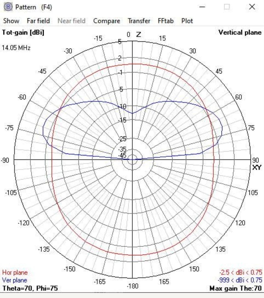
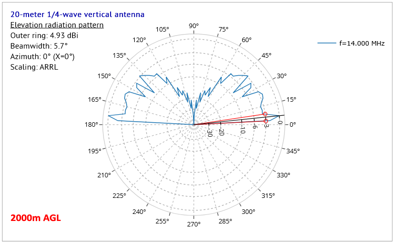
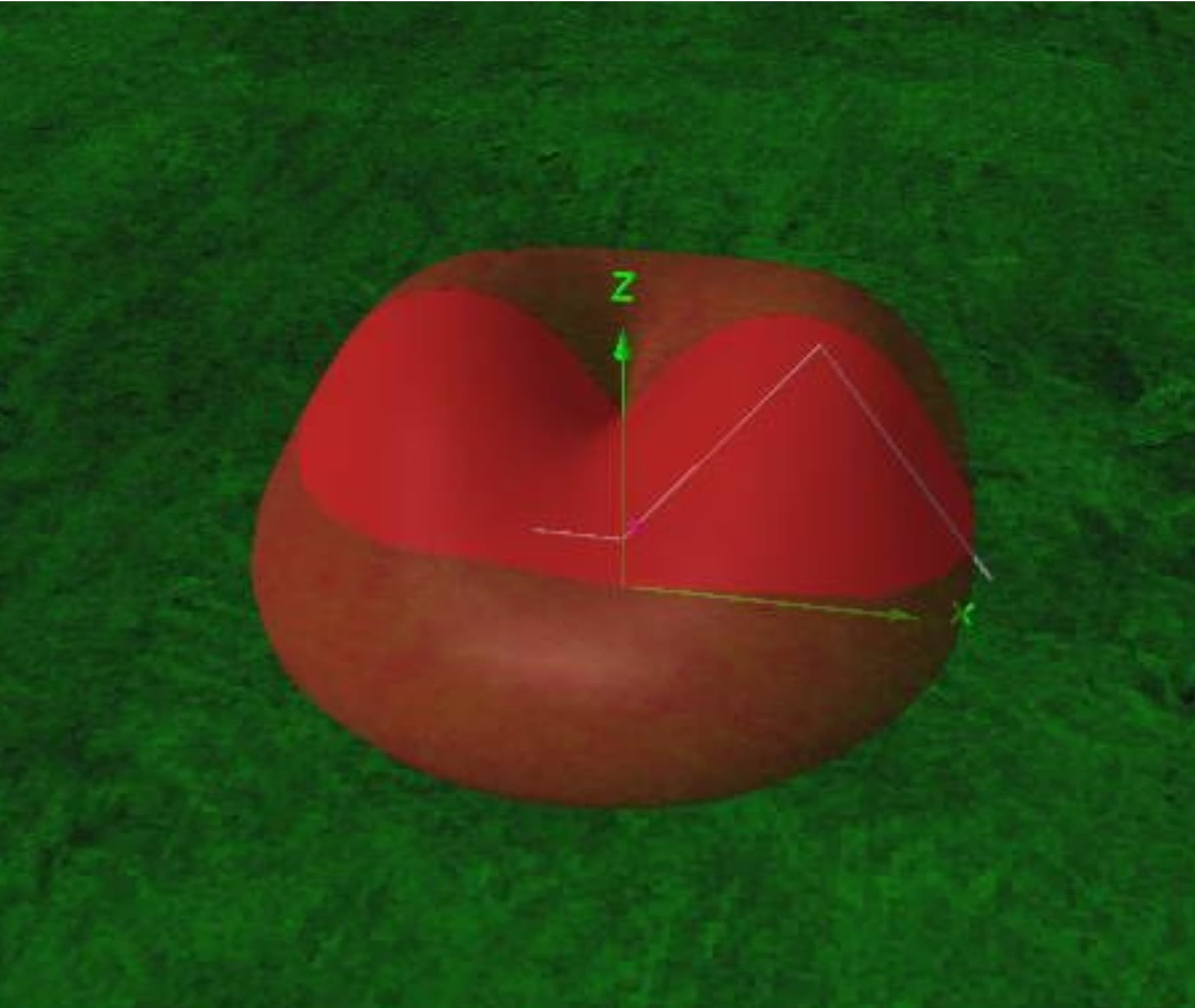
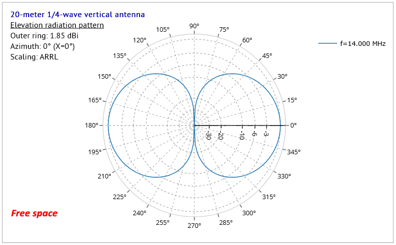
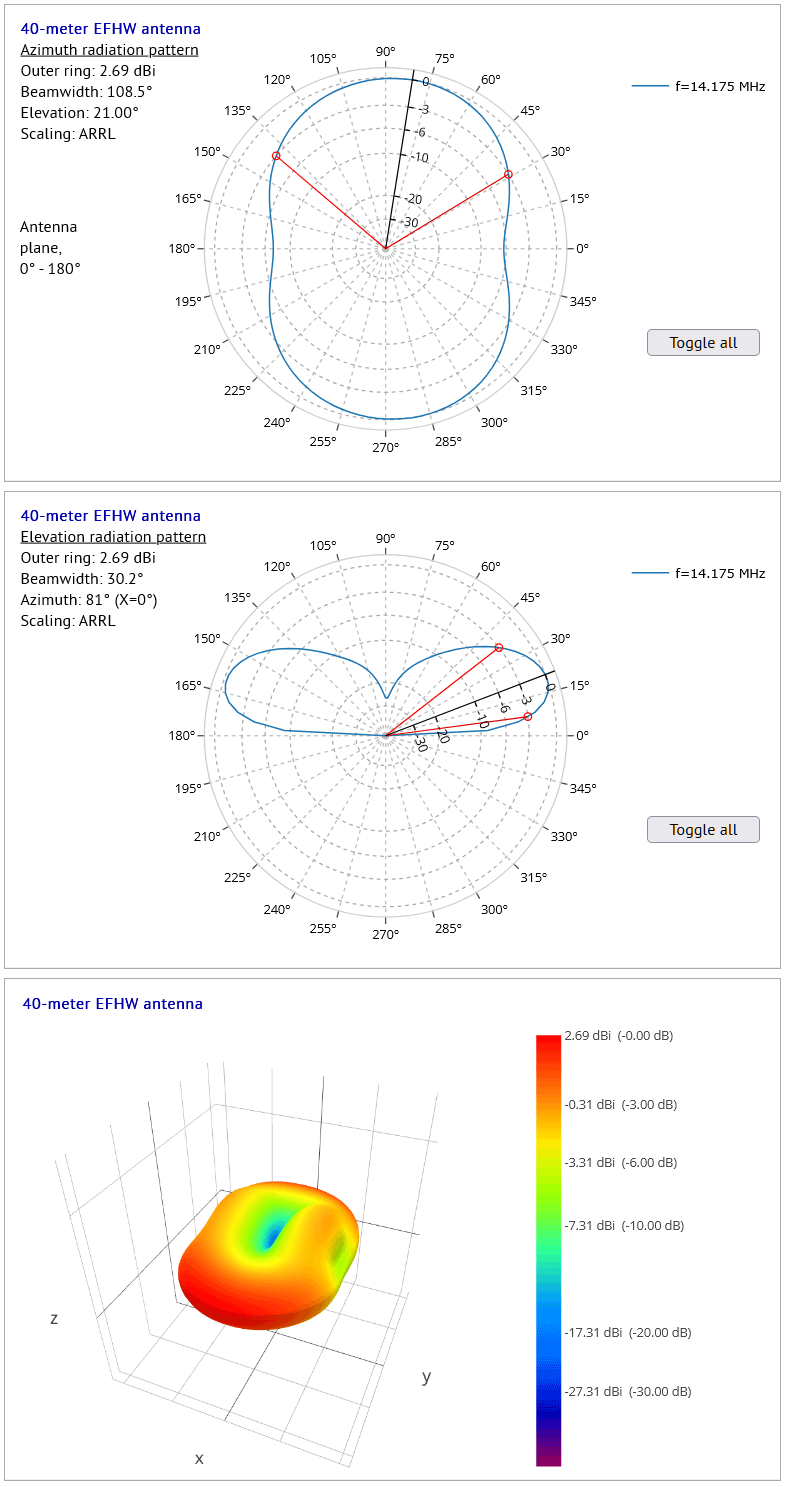
14 MHz no coil, full size
18, 21, 24, 28 MHz / no coil, pole shortened to match. I did the measurements of SWR with NanoVNA once (on the first summit) and marked the appropriate segment of the pole for each band.

I’ve been to about 15 summits with this setup so far and did not need to change anything. I do check the SWR with my QMX every now-and-then and except 7 MHz it is always below 1:1.5. The 7 MHz is certainly compromised, but it works sufficiently well for the local EU contacts and the SWR is good enough to not activate the SWR protection circuit of the QMX.

It’s very difficult to judge the performance from the QSO’s made and RBN reports collected, but it seems to work. I managed to work few W’s and JA in average conditions with 5 Watt output.
The whole antenna set weights about 450 g, the QMX and 10000mAh powerbank another 450g.

EFHW is certainly faster and simpler approach, but I love to try DX whenever possible. Whenever weather and time schedule allows, I spent couple of hours on the summit, hence the 15 mins needed to properly build the antenna is well invested time I believe. I even managed to activate two summits in a day during my 4-day hiking trip, while covering about 17 km distance the same day (including all the necessary activities to survive on a hike, i.e. cooking, water filtering, packing/unpacking and building the shelter etc. The day is long in the summer :-).

73, Jiri OK5WA

6 Likes

I’d like more details. An aircraft using this vertical at an altitude of 2,000 meters is inaudible on the ground? That would be very interesting for the military.
73 Chris

2 Likes

The image shows the dimensions of the EFHW somewhat unclearly in yellow. The short, horizontal piece, approximately 2 meters long, on the left represents the counterweight in the form of the coaxial cable. Then the Unun (invisible) at a height of approximately 2 meters. And the EFHW consists of two 10-meter sections of 1-mm diameter wire with an angle at the top of approximately 90 degrees and a maximum height of approximately 10 meters.
The red tomato shows the three-dimensional radiation diagram.

73 Chris

1 Like

Ouch! - I jumped without looking, mea culpa :frowning: !

I think that this kind of modelling, where the antenna is VERY high, is best handled using a “cliff” approximation when using NEC to generate the data - I’ll look into this.


EDIT #1: I think the problem is that the NEC engine just cannot handle the situation at all, even using a cliff simulation. The cliff solution (using an extra “GD” command to specify it) produces a pattern very similar to the one I gave earlier for the vertical at 2000 meters AGL.

EDIT #2: The actual pattern at great height would be rather like this pattern for free space:

which would certainly keep the military happy!

1 Like

Yes, I get the same results, but I was confused by your description, hence my wishing to have some dimensions. It’s actually an EFHW built for 40m, and being used on the 20m band:

2 Likes

Thanks, Rob, for responding so thoroughly to my post.

I determined the radiation pattern of the inverted V years ago, and I wasn’t sure if I’d calculated everything correctly. I’ve been using this configuration for almost every activation for years. I’m willing to accept the -6 dB attenuation in the longitudinal direction versus the maximum of 2.6dbi.

Since I enjoy S2S the most, perhaps the biggest advantage is that the EFHW is not only very good on 40m and 20m, but also works quite well on 80m (- 6 dbd) up to very well using a tuner for 60, 30, 17, 12m. And it does the change in seconds, as quick the relais of the atu clicks. :blush:

73 Chris

3 Likes

Well those plots look suspiciously like an elevated dipole, and nothing like my models of a 20m long EFHW with a 5m high centre and 1.5m high ends. this model has a long counterpoise for some reason

These are compared at low radiation angle against a 7.6m vertical M3KZZ (without ground wires) made from an aliexpress whip atop 2.7m fglass. I have chosen at 75deg elevation at a favorable azimuth angle for the EFHW on 20m band.
The M3KZZ is tuner dependent (I don’t use one), what I am actually using at the moment is just a vertical efhw linked to be resonant for 20 or 17 or 15.

My reason for trying the vertical is partly to have a faster to get on the air antenna I can just put straight up without any radials etc.

I have been modelling verticals, and I only just noticed that the radiation efficiency is always very low approx 12%.(steep rocky gnd). Only if you use very high ground conductivity does the vertical have decent radiation efficiency. (Luckily, part of the reason for doing this is the 80/40m contest, where our site is right at the edge of a sea mudflat, so good conductivity)

1 Like