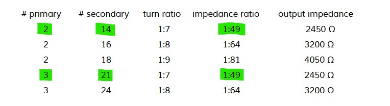
Having never built a 1:49 transformer by myself before I wonder if there is any difference between winding 2:14 or 3:21 turns on the toroid. I found different winding methods which should all be leading to the same result:
1 ferrite core FT-50-43 with 2 primary turns is approx. 27.5% (rest for heating…), with 3 primary turns approx. 68% (rest for heating).
2 stacked FT-50-43 with 2 primary turns is approx. 64% (rest for heating), with 3 primary turns approx. 84%.
A big question mark for me is the permissible transmission power.
The approximate calculation of the magnetic flux with 10 watts and with 1 ferrite core is in the order of approx. 270 or approx. 180 gauss and with 2 stacked ferrite cores of approx. 135 or 90 gauss.
For comparison: To avoid an impermissibly high heating of the core material, Amidon recommends not to exceed a maximum magnetic flux of approx. 40 gauss.
This would be 2 stacked FT-50-43 ferrite cores just on the safe side with a max. transmission power of 2 watts.
From my humble point of view, the developer should add these calculations and corresponding tests to his offer, he could take the contributions of Owen Duffy as a guide.
what frequency ?
The reactance Rx of the primary winding depends directly on the frequency. Rx = 2 x pi x freq x inductance
Rx should be at least 100 ohms > 50Ohm of the trx.
Thanks for all your answers … especially enjoyed watching the video by MM0OPX!
And my apologies for not searching the reflector well enough. It looks like all my questions were already answered in the previous thread Trapped EFHW match unit.
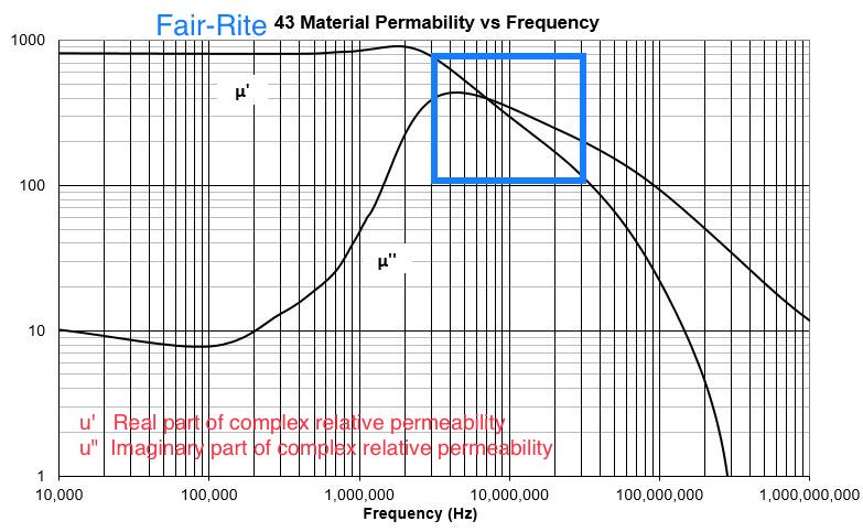
Yes, because the permeability of the ferrite material is complex and frequency dependent, the transformer efficiency will vary by a few percentage points.
And yes, we are talking about a classic HF transformer and NOT a transmission line transformer using bifilar, trifilar or quadrifilar transmission lines, as this statement by DL1CR suggests: “what frequency ? The reactance Rx of the primary winding depends directly on the frequency. Rx = 2 x pi x freq x inductance
Rx should be at least 100 ohms > 50Ohm of the trx.”
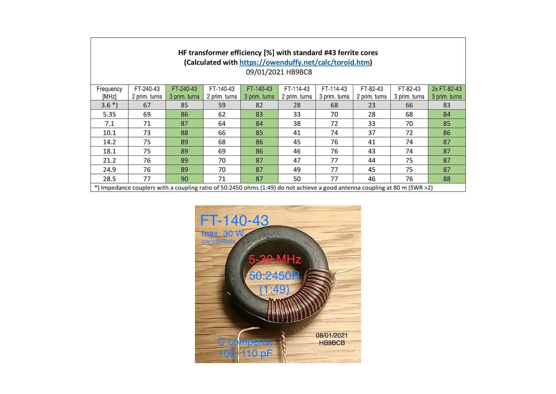
The efficiency values above apply to the 7 MHz frequency band, they get progressively worse as you go down in frequency and get better as you go up.
In the case of ferrite cores with an unsuitable geometry (quotient of cross section and mean field line length) such as e.g. FT-37/-50/-82/-114-43 this efficiency difference to 7 MHz is up to approx. -5% at 3 MHz and up to +5% at 30MHz.
With ferrite cores of suitable geometry such as e.g. Fair-Rite 2643625002, 2643251002, this efficiency difference is only up to approx. -/+ 2%.
Caution
With all these calculations, measurements on the laboratory bench, product comparisons and above all with the respective conclusions it should be noted that the permeability of the ferrite material varies by up to 20-25%, even if from the same manufacturer!
I never do mathematics so I trust you all. My understanding of efhw transformer is:
Use 1:14 or 1:16 depending of antenna impedance. Various shapes of antenna gives various impedances.
For 80m use 3:21 windings. 80m needs more inductance. For 40, 20, 15 and 10m use 1:14. For 40m no need for primar parallel condensator. For 20 and expecialy 15 and 10m capacitor is esential. Capaticance works against inductance on higer bands. Never try but maybe 1:7 windings would be better for 15 and 10m only transformer, I dont know.
Use two or three toroids. That lowers loses. In this video from MM0OPX you could see that “higher” cores have lower loses.
Material 52 is better than 43.
I personaly use 2x140-43 cores with 1:14 windings and choke with one 140-43 core. With this configuration I need two counter poises quater lambda long for every band. For ft818 and 20m only I made little parallel circuit. Primary two turns and secondary enough to resonate with capacitor on 20m band. Adjust wire lenght for lowest swr and ft818 shows two bars maximum in whole band.
There is one german web site, I forget adress, with rf current mesurements in different configuration of efhw. They measure current in antenna, counter poise and coax with or without choke, with or without ground connection of primary and secondary windings.
Well done Martin, congratulations. No doubt this would work.
What transmission power did you use in SSB?
BTW, My Slim EFHW coupler (FT-50A-43, 3/24 turns) that I built in 2016 for use with the MTR3B (4 watts) also gave me quite remarkable results (1225 QSOs, of which 21 dx (W, VE, VK, ZL) and 170 s2s with a total of 28 activations).
Because Owen Duffy said that the number of QSOs says nothing about the quality of an EFHW coupler from his point of view, I was motivated enough to improve it up to and including using a Fair-Rite core 2643625002.
The question that has not yet been clearly answered is the maximum permissible transmission power for a toroidal core with a specific geometry. For example, Owen Duffy recently suggested that the average power of uncompressed SSB telephony is only about 5% of PEP. Thus a slightly smaller reduction could be expected in CW.
And what I also thought about this thread, it is not completely impossible that the Tiny EFHW Kit offered by HB9ZHK is based on my Slim EFHW coupler design from 2016 (Slim-EFHW-Koppler.pdf)?
But these days it’s very common to copy without attribution …
I won’t do that anymore because I’ve turned away from the EFHW antennas for some time and towards a 10.90m long inv-L multiband antenna.
I have shared my “wisdom” about the design and construction of EFHW impedance transformers several times on this reflector. All points to be considered can now also be found in the report Portable 7 Band EFHW Antenna by Stephan@HB9EAJ under this directory Technik und Software – HB9SOTA
73 gl, Heinz
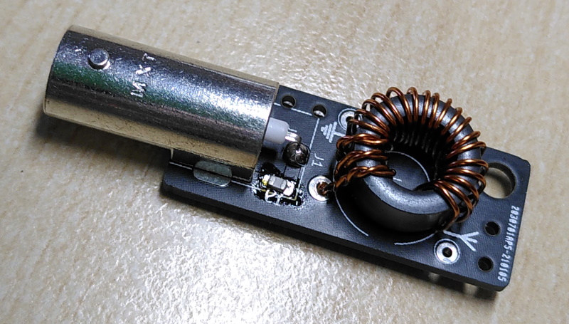
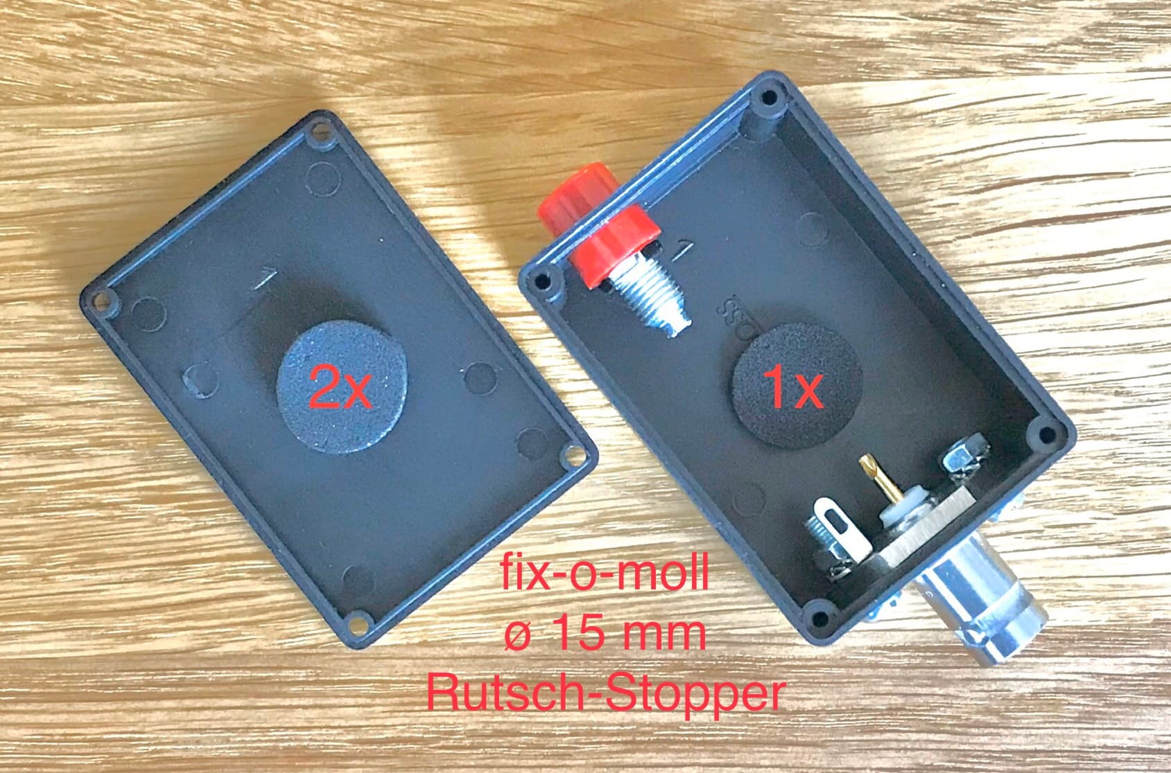
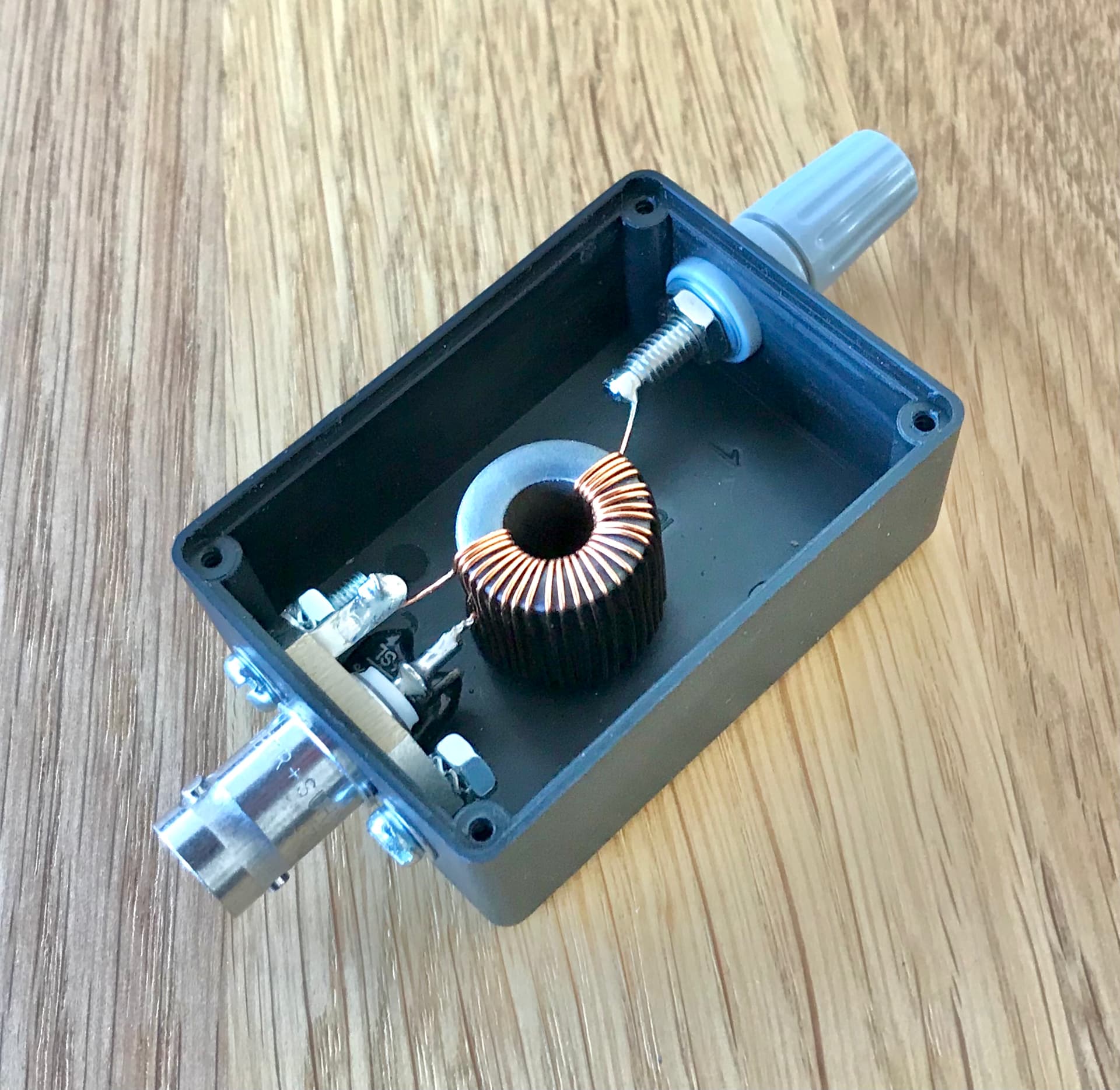
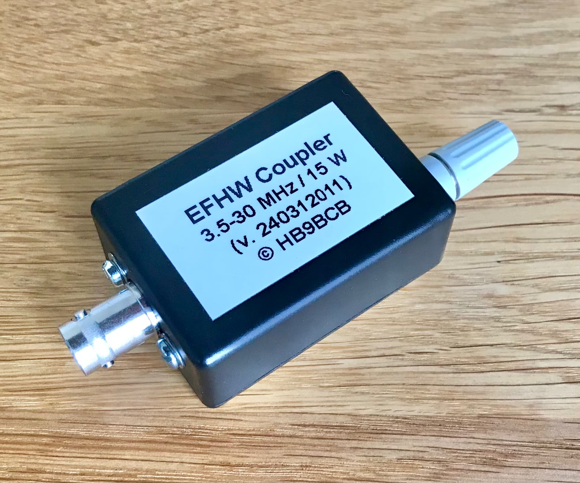
Here are some details and photos for the construction of my EFHW couplers using the small #43 core from Fair-Rite:
Housing: Camdenboss RX2008/S-5 (e.g. from Farnell)
Ferrite core: Fair-Rite 2643625002
Wire: 0.5 mm CuL
Compensation capacitor: 100 pF/500 V (e.g. from Funkamateur online shop)
Would anybody in here sell to me 1 - 2 Fair-Rite 2643625002 from his surplus? It seems they are sold out in Europe, and getting them from the US seems a lot of effort to me.
Please DM me if possible (or email via QRZ). One would be enough, two pieces would be great.
The mentioned alternative from Würth would be ok from the point of view of the core geometry, while the initial permeability is probably a bit too low for best values.
But, as is well known, the properties of the ferrite material are subject to a tolerance of up to +/- 20 % … so one would have to make a comparative measurement, or just be on the safe side and choose the known.
The initial permeability of ferrite materials is
620 for ferrite material 4W620
800 for #43 ferrite material
No information can be found quickly about the complex permeability (u vs frequency) of the material 4W620.
What a coincidence, bought some EMI suppression cores from dx-wire (Peter Bogner DK1RP) about 12 years ago. The ferrite material was specified as Ferroxcube 4S2, which I didn’t know at the time.
And today there is also a core with the dimensions ø 16.25/7.9x14.3 mm available in the dx-wire online shop, that could be interesting, hi.
Indeed, after a very rough interpolation of the complex relative permeability (u’ and u") from the Ferroxcube datasheet for the 4S2 ferrite material, using Owen Duffy’s calculator for “Ferrite cored inductor at HF”, with 3 primary turns, the approximate values are:
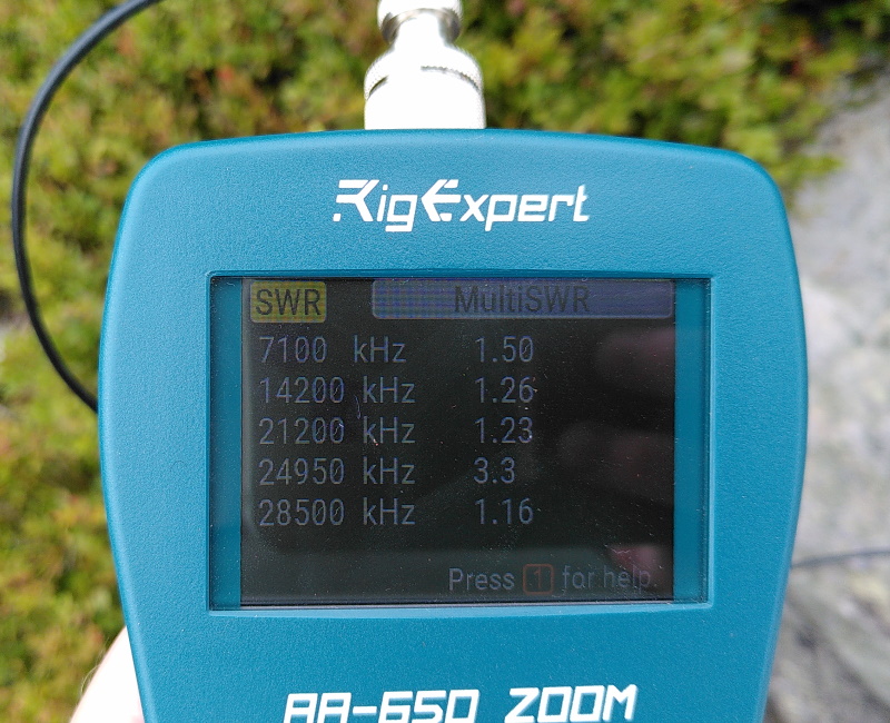
92.5% on 3.6 and 7.1 MHz
93% at 10.1 MHz
93.5% at 14.2 MHz
94% on 18.1 and 21.2 MHz
94.5% on 24.9 and 28.5 MHz
Conclusion
These efficiency values with the 4S2 ferrite core (initial permeability 850) are even a touch better than those with the “original” Fair-Rite core 2643625002.
Almost nothing should go wrong there, have fun with it.
This Ferroxcube ferrite core is available from dx-wire and costs € 0.90