I have a Hamshop.cz Trapped EFHW for 40/30/20m. I acquired it several FN rallies ago (2017?) as I had some Czech Crowns left from a trip and Juerg HB9BIN recommended it.
It works, I’ve used in France, Germany, Czech Republic, Poland , Switzerland when doing light-weight activations. (Simple walks, small hills etc. outside the UK) But I don’t know if it works well or not. Yes, I make QSOs but I don’t know if it’s better or worse than a centre fed dipole. I only use it when I don’t want the extra hassle of using coax. Sometimes it seems to be good and sometimes not. But as I have nothing to compare it against at the time I don’t know if it’s conditions or not. What I have found is that it seems to work better when either in inverted-L with the about 4.5m vertically up the pole and the rest out horizontal (maybe tied in a tree) or with the end sloping down to about 1m above ground tied to a small stake.
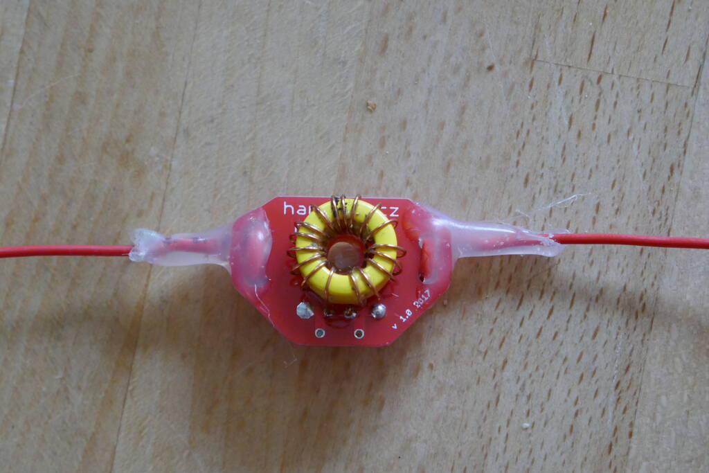
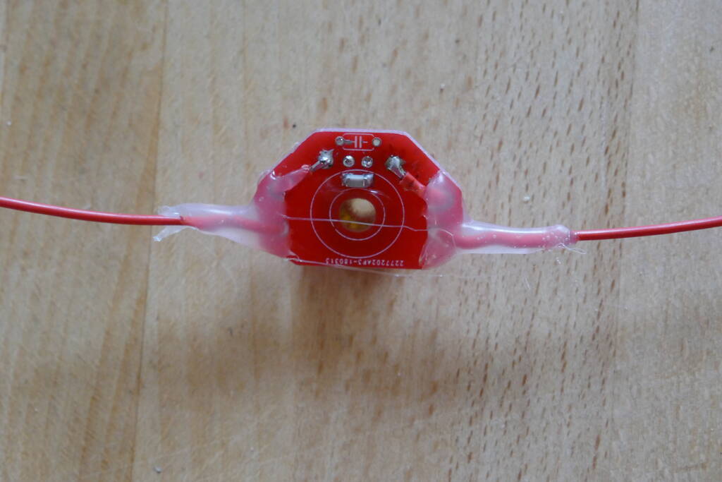
What I noticed on HB/ZH-017 when I was dismantling it was the matching unit was hot. It was about 29C that day and the toroid was very much hotter. Not too hot to touch but hot. Well that’s my RF heating the toroid rather than getting into the antenna! The match is a toroid core with 2 windings, there’s space for a capacitor on the board but none is fitted. The traps have a T50-6 (maybe?)with a winding and surface mount capacitor. My 817 reports more than acceptable SWR for the 3 bands but dressing the antenna is important for best match on 20m.
The question is… should there by some C on the match unit? Or should I make up my own match (AA5TB) and replace the provided one?
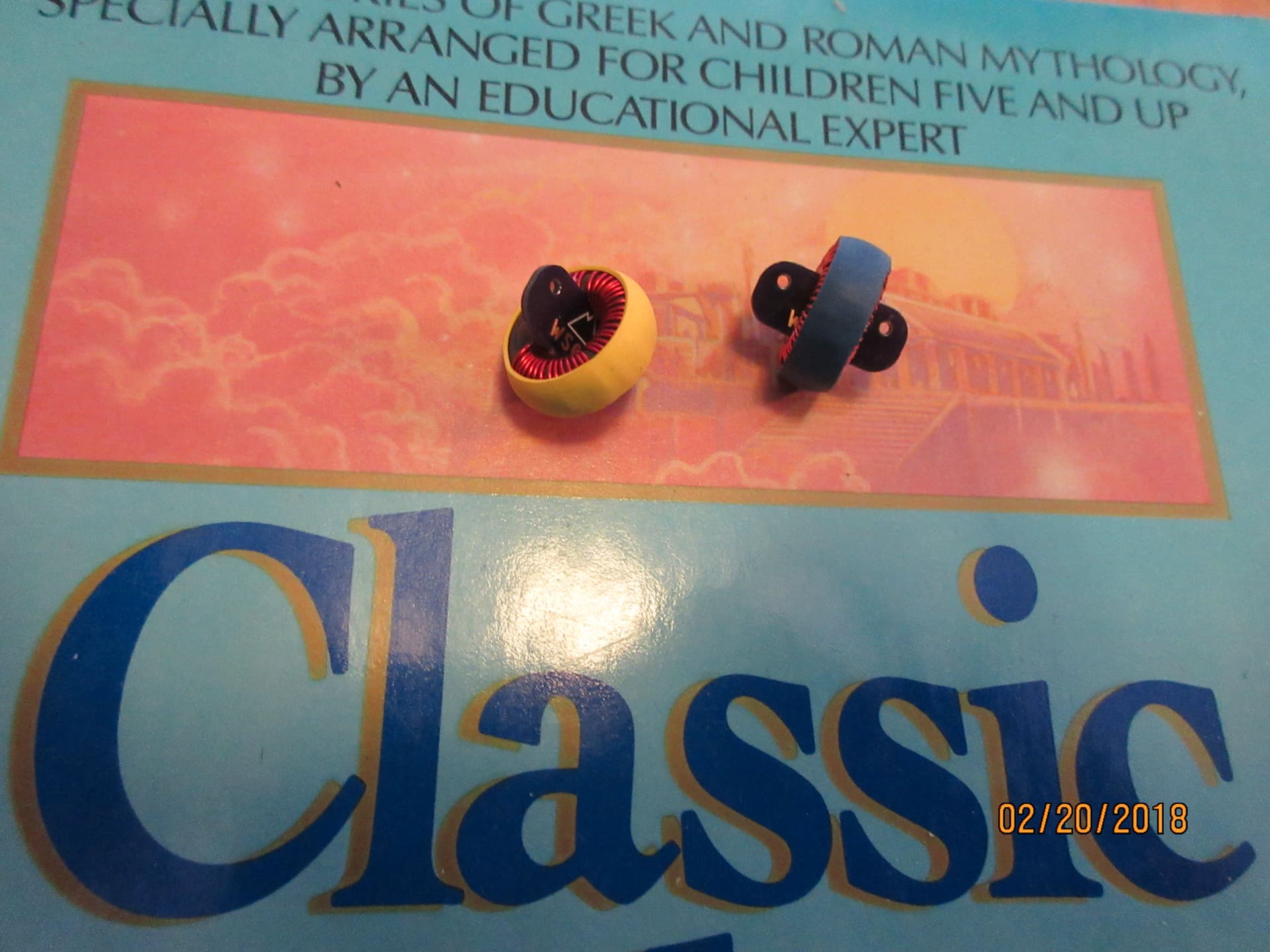
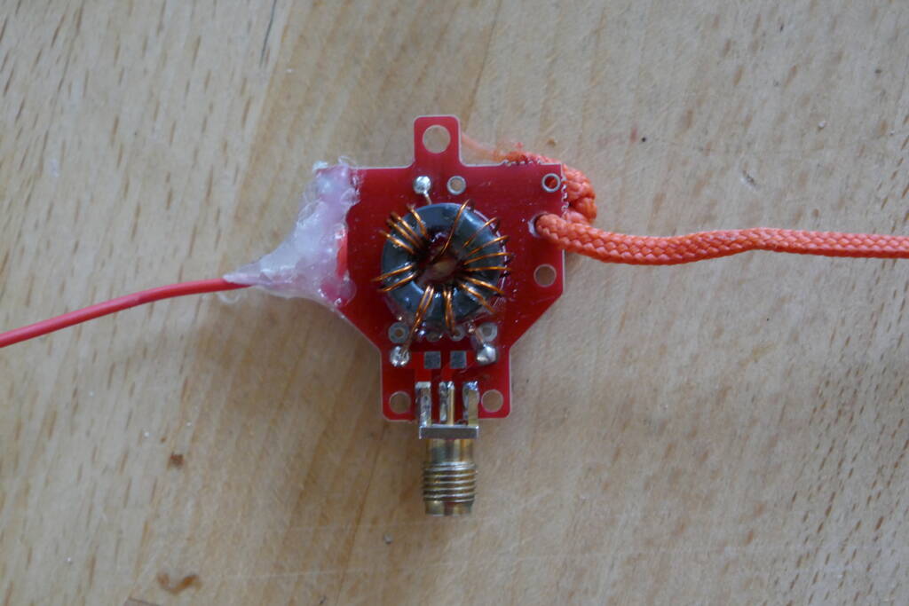
Could you take a good photo of this impedance transformer (not a blurry one) so that you can also see the toroidal core used?
Of course, it would also be interesting to know the inductance (on the secondary side it is sufficient, i.e. between the input and output of the transformer).
At least part of the windings look rather loosely wound - I always wind mine tight to the toroid. I assume thats an SMA so the toroids about 15mm across? Its not big but I don’t think I’d expect it to get warm being fed with 5w (assuming there’s nothing wrong with the choice of material or supplier quality). The capacitor normally provides compensation for higher bands (15, 10m) I don’t think normally you’d need one for 20m. If it was mine, I’d be tempted to rewind it anyway - that loose winding would always annoy me otherwise you need to get it on a nanoVNA with load resistor to see what it looks like.
What I think I see is a transformer with 2 primary turns and 15 secondary turns. Don’t know if that’s intentional or if (how often…) the crossover winding was not counted.
The inductance measurement could indicate whether the toroidal core is made of ferrite mix #43, #61 or another material.
Because this dipole antenna is only designed for 40/30/20m, it is quite possible that a compensation capacitor will not bring any significant improvement and can therefore be omitted.
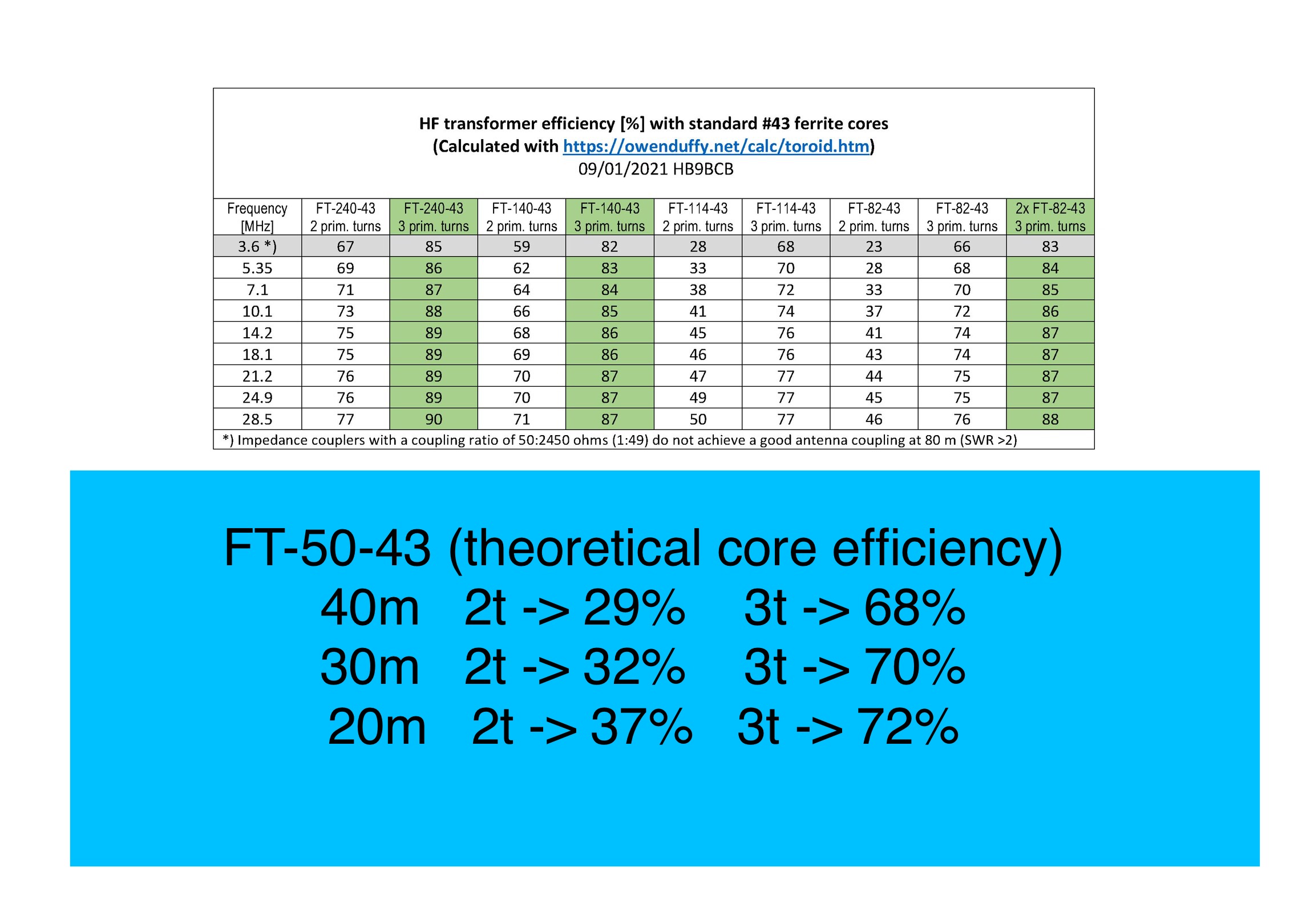
Andy, the core of the transformer is very small. I use an 1.4 inch FT140/43 for my kx2 and yours could be an 0.5 inch FT50/43. For that reason the impedance on 7MHz is only 77Ohm (instead of 150Ohm = 3x 50Ohm) and give you more loss.
EDIT
But it sure works fine anyway. The core only loses its effect at temperatures above 100° Celsius. As long as you don’t burn your fingers it’s fine
Yes, but it depends how you think about them. That trap is high impedance on 20m isolating the rest of the antenna and low impedance on 30m connecting the next section of antenna.
If the toroidal core is actually an FT-50-43, then the theoretically possible efficiency results as in the photo below.
With only 2 primary windings, significantly more power would be burned up in the toroidal core than is radiated.
I myself have never used toroidal cores with a diameter larger than approx. 0.82" for transmission power of max. 15 watts and have never noticed any noticeable heating (with thousands of QSOs), not even with the not yet top-efficient SLIM transformers with a FT-82-43 toroid (with 3 primary turns).
What you should note with this ready-tuned trapped antenna is that the inductance of the secondary winding leads to a shortening of the wire lengths (depending on the frequency).
So if you were to use a larger toroidal core, the wire lengths would be slightly shorter due to the greater inductance. That would be easy to correct at 20 and 40m and possibly a little more complicated at 30m.
I can not assess either your antennas or the traps from the description here. IF… the traps are working properly, then the wire length before any of the traps should be essentially the same as it would be if it was an insulator in that position. IF… the impedance at the end of the endfed halfwave matches the impedance of your unun it shouldn’t get hot and it should present a 1.1:1 load to the TX.
I also don’t know from your description what your are trying to use to match. I have seen folks use a 49:1, or a 64:1, or an 81:1. The length of the wire is likely going to vary a little depending upon which.
Now: I use either one of two matching devices, both home-made and both fit into a dental floss case.
One, originally put forth by Parfits in the 80’s. He sold his business to LNR which makes it to this day. But their commercial one will handle 100 watts, far bigger and heavier than it need be. It is simply 27 turns with a three turn bifilar winding, then 150 pf cap across the TX side which broadbands it for 15-40m. Note that this becomes ever more of a dummy load if it is mismatched, and there is nothing your can do to adjust for such a mismatch in the field.
The other is the circuit your referenced from AA5TB. That is what I prefer as it is somewhat adjustable for site variations. It has always been able to adjust below 1.5:1 and usually 1.1:1.
Go here for details on my trap antennas which have been very effective for me. Of course the EFHW will have exactly the same radiation pattern as a centerfed dipole IF it is deployed in the same shape and location. Getting rid of the coax entirely reduces set-up time, carry weight, and potential for losses.
I would double-check the SWR with a good antenna analyzer before doing anything else. I have read that the SWR function in the 817 is not the greatest. Don’t fix it until you’re sure it’s broken.
With it being a hot day, could it be that the sun was heating the transformer up? Just a thought! I remember my coax feeling hot one time, but when I felt the part in the shade, it was fine.
I think they are very sensible comments Rick. But… I’ve been using 817s since 2004/5 and know what the SWR displays mean on different bands, how many blobs is good, OK or poor. And, I was in a forest in the shade, here’s a picture of the operating position. No antenna as I had pulled everything down and realised no pictures.
In case of higher losses in the transformer the SWR is often lowered by these losses. In case of higher losses the SWR between the working bands is not so high than with low losses.
I would expect that to function better at the higher frequencies than the lower frequencies… FWIW. Nees more turns to work well at the lower frequencies. The Parfits design, 3:24 with a compensation capacitor across of 150 pf across the TX turns may do better across the range. fred kt5x
Andy if your matching transformer on FT52-43 is getting hot @ 5W it must be losses in the core.
As Heins tables show you get only 30-40% of power out to the wire and rest is dissipated in the core as heat. If you want to improve things, I would suggest to rewind transformer to 28:4t as autotransformer, but I am not sure if you will fit so many turns on it.
IMO better option would be to replace existing core for the FT82-43 and to wind 21:3 turns as autotransformer. You should get about 88-92% efficiency ie. power into antenna wire.
If you would like to push efficiency even higher try KN5L method described on his blog KN5L EFHW Unun
Rewinding/replacing transformer might require adjustment tuning for your antenna wire.
I am pleased with the suggestions. I normally would plod on with coax centre-fed dipoles as they fit my UK operation easily. I’d not bother with antennas like this simply because they can be “involved” to make them work well.
However, I now understand why people have been experimenting with these designs. I have something that sort-of works. I now have some ideas to try to improve it and see if I can get the efficiency up.
I made a 40m EFHW with a 49:1 transformer which I use as a sloper (with coax up to the top).
I can’t find the instructions that I followed (maybe this one? Chez TK5EP ) but it said for 40m you didn’t need a capacitor across the transformer but for 20m and 10m a capacitor would help.
My FT817 gives 0 SWR blocks on 40m, and 1, maybe 2 blocks on 20/10m. I’ve made voice contacts on 40m and 20m with it and FT8 contacts on 10m, although I have more success if I elevate the low end by attaching to a fence post.
 otherwise you need to get it on a nanoVNA with load resistor to see what it looks like.