I have just been looking through some linked EFHW designs both on the web and in this forum as I want to build a lightweight antenna to use with my little G106 radio.
I was intending to add links into some lightweight wire (the wire that is normally used to fix errors on PCB tracks - I have used this before and with care, it is OK for antenna usage at low power).
Here’s an “off-the-wall” idea…
Having read a comment that resonant counterpoise wires can be simply taped together (indeed I do this for one of my loaded vertical antennas) to make deployment simpler, I wondered, what if I do the same on the driven element side of an EFHW? i.e. have multiple lengths of wire (one length for each required band) wired together at the tuner connection and taped together up the length of the antenna. The wire collection gets thinner and thinner as each band’s wire comes to an end.
Would the RF signal select the resonant wire for the band you are transmitting on and effectively ignore the other wires? (Similar to what happens when using a fan dipole.)
Having the other wires there will probably affect the required length of each band’s driven element but this can be adjusted using an analyser during construction.
I’m sure I’m missing something … If this were possible, even with reduced performance, it would avoid the need to drop the antenna to change bands, a re-trim on the tuner may be all that is needed.
Has anyone tried this in the past and has actual results?
What you’re referring to is essentially a fan end fed half wave, with similar construction to a fan dipole. Bottom line - this doesn’t work.
Why?
EFHW antennas are fed at a the voltage maximum/current minimum which is the high impedance point on the antenna. Dipoles are fed at the voltage minimum/current maximum which is the minimum impedance point on the antenna. In the dipole, the non-resonant lengths of wire present a higher impedance and the current flows down the proper wire. In the fan EFHW, the non-resonant wires will present a lower impedance and will take the current even though there is an impedance mismatch. The result will be high SWR.
That said, the nice thing about the EFHW is that it’s resonant on all even and odd harmonics. So a 40m EFHW is resonant on 20m, 15m, and 10m (sometimes with a little tweaking). Other bands like 17m, 12m, or 30m can easily be added with links.
The wire for the 60, 30, 17m endfed is a bit longer and you can hang it over the other endfed on the same mast (both as inv. V). Then you only need to reconnect the antenna on the TRX.
The antenna I use has only 1 link spot Ed its at about 9.7 mhz resonate to give a better vswr on 17/12m. The vswr on 10.1 in the 30m band is 1.7T1 so my FT817 knows no difference and my use of 30m on SOTA is not very often but 17m is used to work into JA. The only thing I don’t like about this antenna is I never get up to change links during the activation and my old body get sore from sitting so long in the one spot. But this antenna gives me 40m to 10m all bands and is my afternoon antenna as the 80m band is always used during my morning activations so I deploy the usual link dipole. Usually config EFHW inverted L style using my walking pole on a post or stump/bush to get the vertical part then across to my carbon 6 pole at the far end. Its fed with 4m of RG174.
Regards.
Ian vk5cz …
Thanks for mentioning to Ed @DD5LP about my solution.
Let me just add that in the meantime, I use it actually on 8 bands without a tuner (60-10m).
When I designed it, I measured a resonance on the lower 11m band (open coil), but since it’s not a ham band, I didn’t count this band.
Since I have a TRX with an included SWR meter, I realized that thanks to the 5 meter long RG174, the SWR is good enough on the 12m band (<1.5), so I could do some few DX on this band during this summer.
Of course, the radiation pattern on this band looks probably nearly as bad as on 10m, but better to have a usable antenna than none.
In this respect, your trapped EFHW should be much better on the higher bands.
For this reason, I always carry a shorter EFHW with me, not only for restricted size summits or as a spare antenna.
Update: Adam @K6ARK thanks for your input, very well explained!
In this context, a trick that I tried is to add a short wire at the antenna feed point to simply shift the minimum SWR down in frequency.
There are several calculators in the net, I used this one. If you wind a 0.5 mm wire onto a 25 mm plastic pipe you should need about 3.8 m of wire and 48 turns to come to the 35 uH. If the diameter of the wire is smaller, the number of turns will also be less. [because of N²/l]
73 de Peter, DM7KN
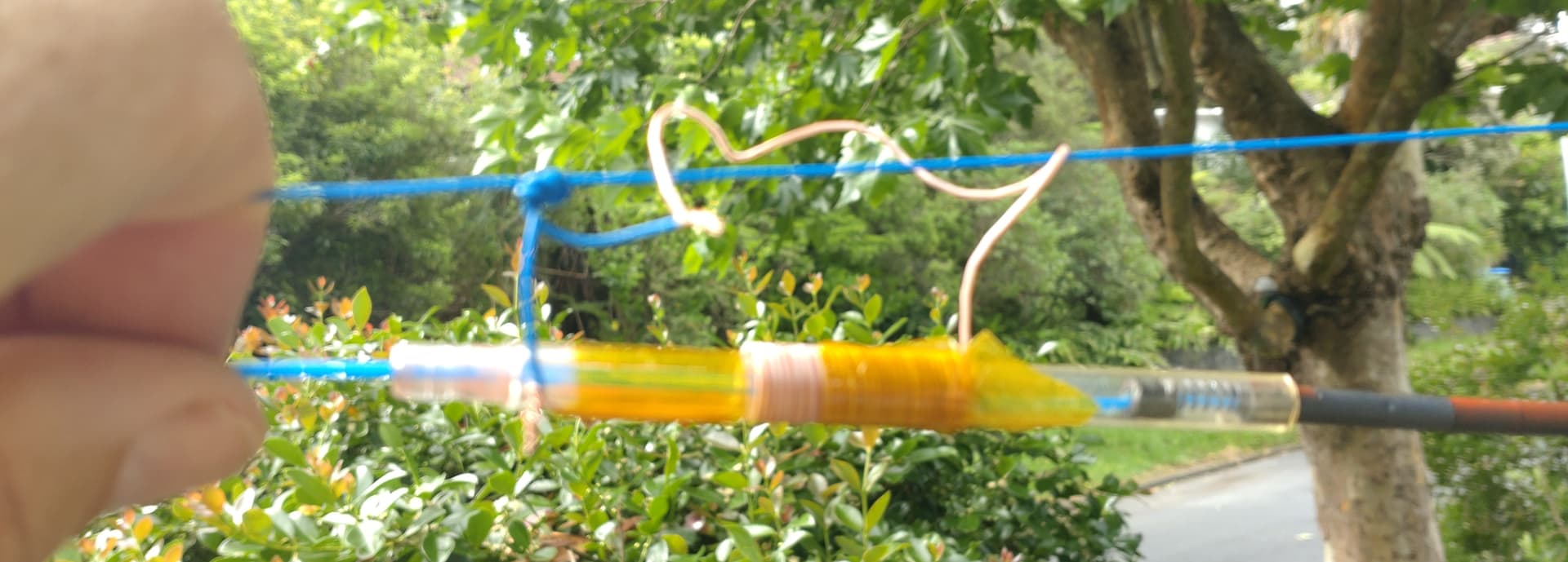
So here is what I have actually tried today in my antenna. This is a first try
It’s a coil wound on a pen tube. I have made a ferrite rod (right side of picture) from some 5mm OD , 4B1 material beads strung together. It is ~3m from the far end
Ferrite rod out - 40,20,15,10
Ferrite rod in - 60,30,17,12
WX is a bit wild, so I haven’t tried moving it’s position along the wire and optimising the band fit, but the first attempt is looking workable for all bands.
As it is today, it would work perfectly with a mild autotuner.
So the objective is:
no connectors in the wire. The coil is wound with the antenna wire, so it can just be wound into the antenna rather than cut in.
narrow and physically inline, so it can be pulled through foliage if needed.
I want 2 band groups without tuning, although it does allow tuning of the antenna.
modelling indicates I can get 80m with 5m more wire on the end.
Currently coil is 8mm mandrel. 31 turns 46mm long.
Calculated inductance without core 1.8uH.
Cores should be 2x coil length to keep Ueff of the ferrite rod high.
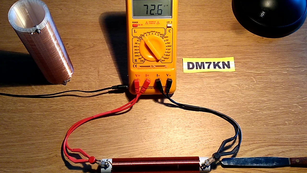
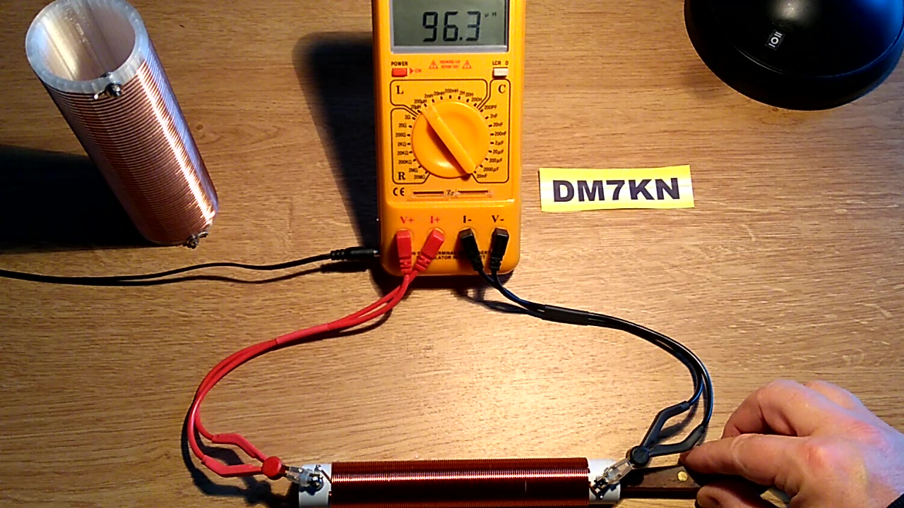
This is a funny coincidence. Inspired by the video posted by Chris@DL1CR, I was thinking about the many soldered connections he had on his coil and if there was no easier way of tuning. So I played around with a few coils and different materials I had at hand. Since I did not find a ferrite rod, I experimented with brass and Al pipes from Yagis and ultimately with a stainless steel spatula from my desk.
The range is surprisingly wide, from about 70 µH to around 100 µH. I have not driven this any further, but a threaded rod and a nut would open the path to fine tuning. (This is not new and realized several times by others).
I tried the same sort of thing using an aluminium sleeve (as well as wrapping it in al foil) as a big shorted turn. Unfortunately I couldn’t get the high ratio inductance change I wanted for a general purpose ATU.
Hi Simon,
as said, I also experimented with Al and the effect was limited. This can be explained by the “μr” of Al being relatively close to one. Permalloy, an Iron/Nickel alloy - just for comparison - has a μr of around 100000. My Spatula shown in the pictures is made of stainless steel, which is usually an Fe/Cr/Ni alloy. I am not an expert in those things but this is my explanation why my spatula worked better in the experiment than my Yagi Al pipes.
Stay curious and all the best for your experiments.
73 de Peter, DM7KN
The anticipated effect of the aluminium sleeve was that of shorted turns, rather than any u effect. I must look more closely sometime, and see if it could be usefully combined with contacts/switches to give continuous adjustment with a limited number of switches.