Magic length of vertical wire for KX2 antenna tuner ?

Hello,
,
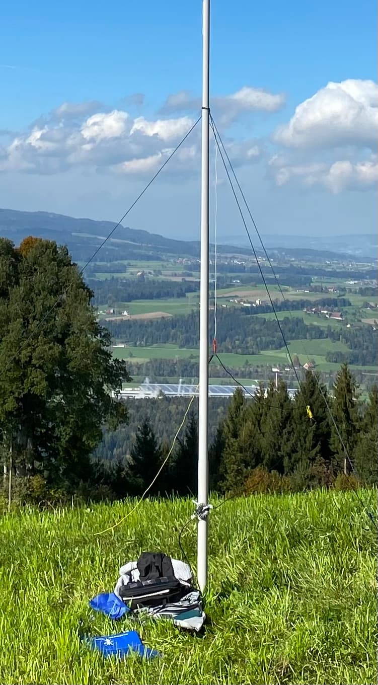
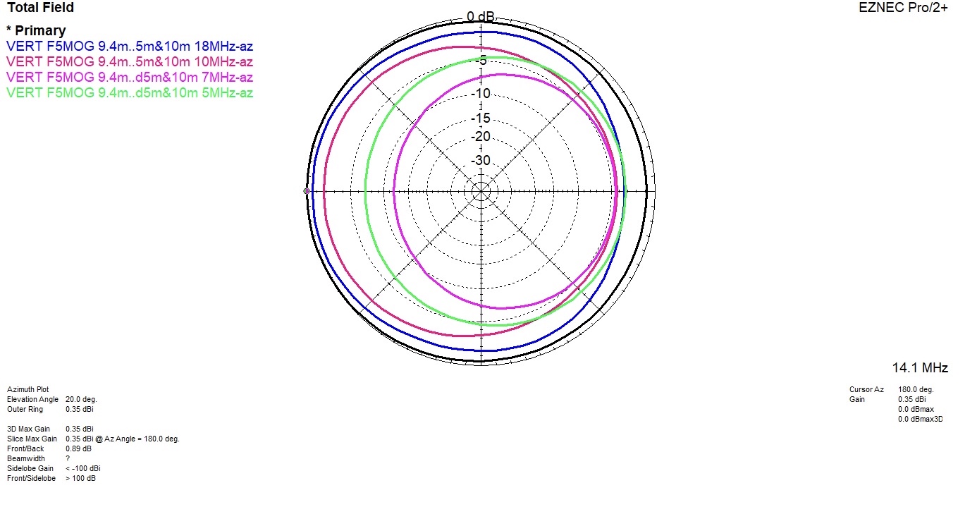
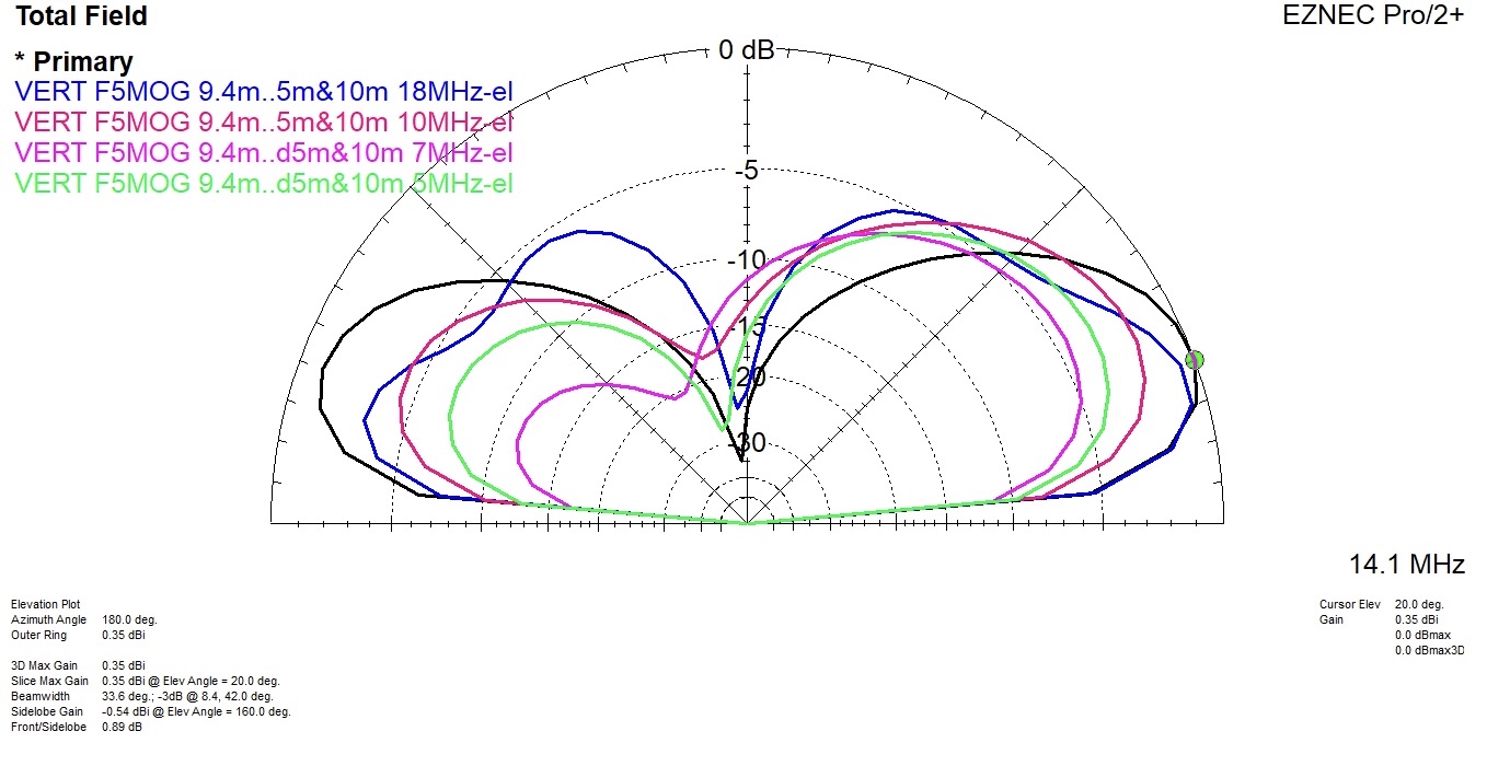
As an antenna, for the simplicity of use, I use a vertical 9.38 m wire, on a 10 meters fiber mast (DX-wire mast), and 2 radials on the ground, 10 and 5 m.
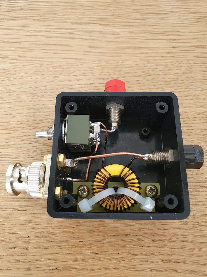
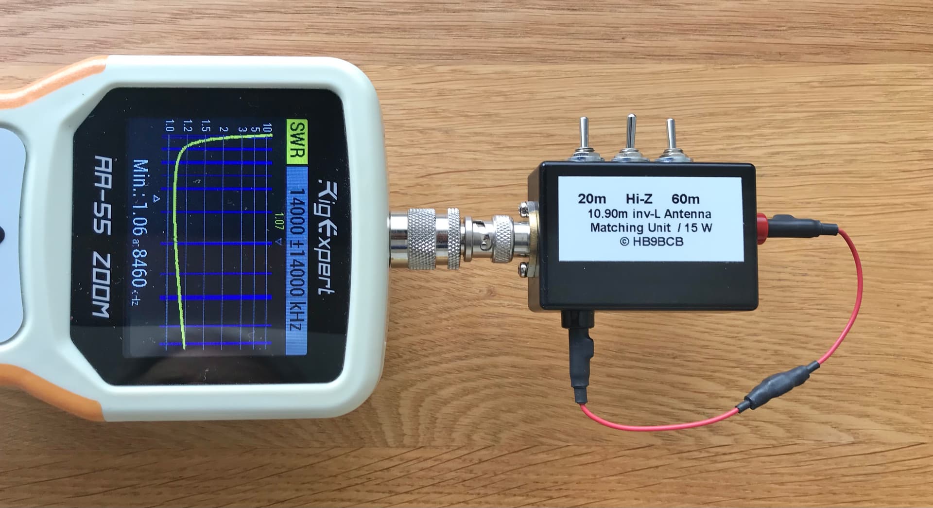
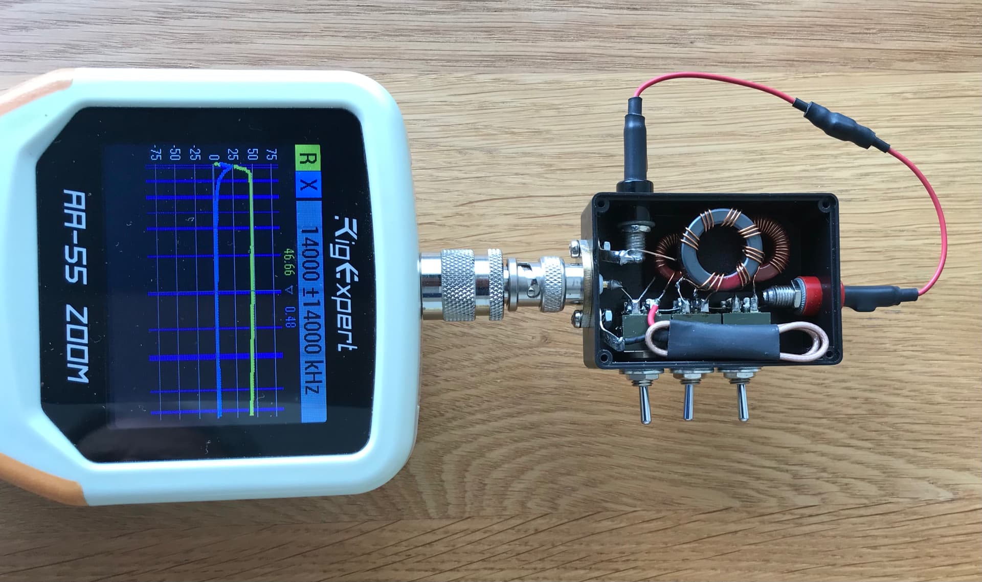
With my rig, an ALT-512, I have a T1 elecraft tuner, which finds a perfect match on 60-40-30-20-17-12-10 m. (cw part of the band)
I recently got a KX2 with its internal tuner. Seems that the internal tuner does not have the performance of the T1. I obtain a perfect match on 60-40-30-17-12-10. But on 20 m, at very best swr 2.5, often more.
I tried a recommended length of 7.50 m, as per KX2 manual, but with this length the 18 MHz does not match.(again lambda/2 on 18 Mhz)
My favorite bands are 40-30-30-17 m.
So, among the KX2 users, any recommendation of a magic length of wire, accepted by the kx2 antenna tuner, suitable for 60 to 10 m, (or at least 40 to 17 m.)
Or a trick, eg a tranformer (how to ?) to be switched in my existing set-up, to be used only on 20 m, to bring the antenna impedance in a range acceptable by the kx2 internal tuner ? Any experience in the sota community ?

73 de Pierre F5MOG

4 Likes

Hi Pierre,

Your length of wire (9.38m) is very close to the half-wavelength on 14MHz. This will present a very high impedance at the feed-point which is a problem for any tuner. Even if it can be matched do not expect a very efficient system.

When you shorten the wire to 7.50m you are now very close to the half-wavelength on 15 and 17m resulting in the same problem, but now on different bands.

In general you should avoid tuning a wire close to a half-wavelength (or a multiple thereof) with a built-in antenna matching network.

Alternatives would be to use the original 9.38m and use either a step-up transformer (currently discussed in a parallel thread (Toroid windings for EFHW) on 20m or a quarterwave length parallel wire tuning stub converting the design into a J-pole. For all other bands you could use your KX2 with tuner.

Another alternative would be to use the shorter 7.50m wire on all bands except 15 and 17m and use an additional clip-on wire for these bands. Again avoid going near half wave on any operating frequency.

73 Heinz

5 Likes

On my KX2, I use 57’ of wire for the radiator and 17’ for a counterpoise. I’m able to get <2:1 matches (usually <1.5:1) on 40, 20, 17, 15, 12, and 10 and have used all of those bands to make contacts.

Lately, I’ve been experimenting with a 16’ “golf ball retriever” from Amazon. Connected to a 9:1 unun, 16’ 4-wire radiator, and 30’ of coax, I’ve done some good work on 40, 20, 17, 15, and 12 (nothing yet on 10m). The “golf ball retriever” is $23 shipped from Amazon. It looks every bit like an extendable whip antenna. :smiley: I can set it up and get on the air faster than I can with my “long wire”.
There’s a good discussion going on at QRZ (look for $20 portable telescoping antenna) if you want more details.

ETA: here is the direct link to the discussion about the “$20 portable telescoping antenna”:
https://forums.qrz.com/index.php?threads/20-portable-telescopic-antenna.827448/

Chris

A simple option for such exceptional cases in impedance matching is still a 1:9 transmission line transformer.

This transformer should be switchable in order to only support the ATU used if it cannot do it well enough on its own.

If the transformer is only used for the frequency bands above 10 MHz, as is the case due to your antenna length, it can be optimized for this (only 7 trifilar turns → small wire length → less losses).

The design of a switchable 1:9 transmission line transformer with a FT-82-43 ferrite core could be done as shown below.


2 Likes

I use the same antenna configuration with my KX2 for over 500 activities: radiator length 9.2 m, single radial 5.1 m (laid out on ground), 10 m mast (DX-Wire mini).

The SWR is really good… with the exception of 60m - there it is just under 3. But you can work with it.

It is important that the radial rests on the ground. If it lies on bushes (e.g. blueberry) or also on snow the SWR is bad.

73 Armin

1 Like

the stub is an interesting idea, thank you Heinz ! a quick connect-disconnect can be designed. Do you think it can work if the stub is laying on the ground ? Coax stub, or parallel line ? Have you tried ?

Thanks for info. However, I like the 10 m or so length, vertical, because of its omnidirectionnel pattern, and low angle (at least on 40-30-20). The short whip, I am using it only when I am unable to erect my 10 m pole…which happened to me only once…

Heinz,thanks, I like this idea, and your compact design. I see 2 tores behind the trifillar. Can you tell me more about your design.

By the way, I found in my shack a 1:4 balun, a chinese thing (quality , efficiency probably questionnable, but this is not the topic). My kx2 atu is tuning the 20m well with it. So my question…better to have a 1:9, a 1:4, unum or ???, or is it only only a matter of incremental losses ?

Hi Armin, the set-up 10 m vertical wire + radial seems to be convenient for our area, the Vosges and the black forest. Well, I used it in many other countries, to my satisfaction.
To check, I just replicated your 9.2 m + 5.1 m radial in my garden. swr 5.0 on 20m, swr 1.7 on 60 m. Same equipment should lead to same results, I feel the dispersion on 20 m is really huge. I played a bit with the height of the feed point, on the ground, or above, to see if losses near the ground would influence. Yes, it makes a difference…but little. So seems to work with you on 20 m. Your internal atu seems to accept much higher impedance, vs mine. It must be something somewhere, which I cannot explain.

To all, what a pleasure to be part of this group, to meet on the air, to hare on the reflector. Thanks !

1 Like

looking here: https://udel.edu/~mm/ham/randomWire/ it seems 70 ft is the shortest length that will give you 80m-10m.

I may have misinterpreted it though.

oops, i missed the vertical mention in the title. I’ll leave the comment in as its a useful link

2 Likes

Maybe It is my coax…

I have a Banana to BNC … Then +- 3m coax … a current balun Amidon 140-43 …. 40cm coax to the KX2

The DX-wire mast is about 9,40m… the antenna is fixed at the top. The banana/BNC is a litte bit above the ground.

73 Armin

1 Like

Yes Armin, without a doubt - with an antenna as unbalanced from an electrical point of view as this, common-mode current occurs at the feed point.

This common-mode current flowing back on the outside of the coax cable shielding turns the coax feed cable (unintentionally or intentionally) into a radial.

As can be seen with EZNEC, this changes the impedances and radiation angles of the vertical antenna.
These changes are “dramatic” on those bands where the additional radial (here 3m) is lambda/4 or more in length.
Also, the values ​​will change if the coax and/or the radial are raised off the ground a bit (could be used to support the ATU…).

This behavior clearly shows that this multi-band antenna is not finished from an electrical point of view.

That’s not to say, at all, that the antenna doesn’t work as is, just that it could do better.


Another comment on the tables on the web mentioned in this thread, which show the supposedly optimal length of antenna wires of random length:

  • All these listed lengths imply that the wires are terminated at the feedpoint with an electrically equivalent system (2nd leg e.g. as a doublet antenna, radials, ground stakes, …)

  • These recommended antenna lengths can also vary depending on the antenna geometry and wire material and diameter used.

So these tables should only be understood as guide values ​​- unfortunately without any guarantee, hi.

1 Like

I actually always assumed that there was a piece of coax between the TRX and the antenna… (Of course, you can also connect the antenna directly to the TRX, but in practice this is disadvantageous… One looks for a place to sit and this is not necessarily the antenna base).
Thus I have automatically (with e.g. an Endfed) with the shielding of the Coax the “second pole”. In my experience, a current balun in front of the device is then useful. With an IC 703 I could not even do CW without it… It was keying itself all the time. That shows how much HF vagabonds there.
By the way, when using it with the described coax, I found that a counterpoise of 0.05 lambda has no further positive influence.

The shortening factors of different wire materials, wire thicknesses and insulations have of course an influence on the antenna length. But in my experience these are not so dramatic when using a tuner. It is quite different when used without a tuner.

Due to the low-cost measurement technology (e.g. NanoVNA) it has become easy to determine the resonances of the wires.
By the way, it is exciting: you can set up several identical baluns 1:49 and hang the same wire on them and the resonance point is always slightly different. There you can see the dispersion of the components and the manufacturing. That’s why it’s often difficult to give general wire lengths for such antennas. If the transformation varies in the range 1:49 to 1:64, the difference in wire length becomes even more obvious.
Fortunately, the antennas are often so broadband that it doesn’t really have a strong influence… and with tuners anyway.

The antenna described above is certainly not the best in the HF range. There is also always power left in the tuner. But it works quite well and is almost unbeatable in the setup when it comes to space and speed.

73 Armin

1 Like

Hello Pierre,
I use my KX2 (with internal tuner) with 2x 7.6m wire. First 7.6m vertical on a fiber mast and the 2nd 7.6m on the ground. I connect the two 7.6m wires to a sym. line (HĂĽhnerleiter :wink: ) about 1.5m long and at the end a 1:1 balun, between balun and KX2 about 30cm coax. It works perfect for me on all bands between 10m and 40m. SWR is on all bands between 1 and 1,5

73 de Sascha, DL1GRC

4 Likes

Pierre,

I used a 9m wire with 4 x 6m radials for several years, with the KX2 internal tuner. But in my case it was an inverted L on a 6m pole, so different impedances. No feed line, wires into the BNC to banana adaptor. It tuned all bands except 17m, in most cases I disconnected the radials on 20m to get it to tune. There is very low radial current on 20m as near a half wave, so works well with no radials attached. Try disconnecting the radials on 20m, or replace with a short 1.5m radial.

The solution suggested by Heinz HB9BCB with the switched 9:1 UNUN is good also. It should not be used on bands where you don’t need it.

I now mostly use a 10.9m long wire, again as in inverted L. Heinz HB9BCB did the hard work finding a good length, in my case I use 11m wire with a switched L network for 20m. See the info here from Heinz https://hb9sota.ch/wp-content/uploads/2021/05/All-band-antenna-for-the-KX2-KXAT2.pdf

My little switched 20m L network is shown below, with a series C (RF Chip capacitor across the switch terminals) shunt L.

73 Gavin
GM0GAV

3 Likes

For what it is worth:

https://www.on6zq.be/w/index.php/Scilab/NotSoRandomWire

Pierre,
Why not put in a link at 7.5 m to shorten the wire for 20 m? As you do not use it much the small inconvenience of occasionally opening the link is probably less trouble than using a balun or longer wires.

I have used a vertical 22 ft wire with two 23 ft length radials and an ATU . The atu’s I tried had no problems matching from 30 to 10 m. Adding another 20 ft wire allowed matching down to 80 m.

My AH705 tuned down to 80 without the wire extension. I haven’t tried a KX2 with tuner but would expect it would gasp a bit on 80 m but might be OK on 40 m without the extension. It is not as good as the AH705.

Now efficiency? Probably varies from OK to ghastly.

73
Ron
VK3AFW

1 Like

A 41 ft radiator with 17 ft counterpoise attached to a 9:1 unun directly connected to the rig will tune from 80 - 10 m.

Adam
K6ARK

6 Likes

Thanks for the different ideas. I want all bands, 60 to 10, omnidirectionnal, low angle up to 18MHz.

I like the idea of switching in, an appropriate impedance adaptation system, just for one band. It allows me to keep my set-up (9.4m vertical + 2 radials, 5 and 10m). It is quick set up, omnidirectional,has low angle to horizon from 40 to 17 m, usable on 15-12-10m with higher lobes.
I use for higher bands, a 5m vertical + tuner, if I really want a low horizon angle.

I tested it with a 4:1 balun, and the kx2 tuner accepted to tune my 9.4 m wire on 20m. Of course, I have the losses of the tuner + the losses of the balun, but I feel it is the price to pay for the multiband versatility. I have no coax, wires directly at the output of the KX2 (or the balun…so no coax losses.
By the way , the balun did not heat during my activation, and I had the pleasure of a USA qso on 20 m with my set-up
So., feasibility test is good enough ! I will make some measurements on my balun, eventually build a better one with less losses.

Thanks for the ideas.

Pierre F5MOG

1 Like

Pierre,

Don’t know what exactly you mean by omnidirectional radiation, since the asymmetry in the azimuthal radiation of your 9.40m vertical with 1 radial each of 5 and 10m length is in the order of ~7 dB at 60 and 40m (in the best case, i.e. when the radials are opposite each other).

And, as basis for choosing a suitable impedance transformer (transmission line or conventional type) for the 20m band, the approximate antenna impedance (R, X) should be known - because as long as the impedance mismatch at the transformer input is too large, the transformer will never be able to heat up, hi (because he only gets to see half or less of the transmission power…).


1 Like

Mmmmh…I did not realize the skew of the lobes were that much ! You are an eye opener for me. OK, I will need to go back to some more fundamentals. something with 3 or 4 radials, same length, to keep the symmetry, with possibly a bottom impedance which can be handled by the tuner.
Or…play with the position of the radials, whenever possible during the activation, to favor the directions of some countries.

thank you Heinz for taking time to model my antenna.

73 de Pierre F5MOG

1 Like

Hi Sasha,

I used this - up and outer - design many years, while camping, with the 2nd leg about 2 m above ground. I started sota with this antenna, but the leg 2m above ground was often not possible to deploy on the summits. So I eliminated the parallel feed line, and the antenna became a vertical with a radial. Then , I added a second radial…for the sake of a better efficiency.
Anyway, good to know that the up and outer design, with the second leg on the ground, is a workable solution.
I may compare your up and outer design my vertical 9.4 and radial (s). I need to master the software first.

73 de Pierre F5MOG

2 Likes

What Adam said. On 40 m it’s about 1 to 2 S-points down on a resonant dipole but so simple to get on the air in a couple of minutes on a carbon6 mast or similar.

2 Likes