Update (February 2026)
The design is now complete, and the first online shops have started offering the final product.
List of shops (will be updated as I become aware of them):
Have you ever forgotten to bring your KX2 charger on a trip, accidentally torn the speaker wires after countless battery removals, or found yourself with a dead phone battery on a summit while the KX2 still had plenty of power? I’ve managed all three. Each time, I wished the KX2 simply had a USB-C port — no more removing the battery, no special charger to pack, and the ability to top up a phone.
External power banks are awkward when operating handheld with the AX1 and may cause QRM. The KXIBC2 option still requires a specific AC adapter, charges very slowly, and cannot supply power to a phone. Perhaps the best solution until now was to bypass the KX2’s built-in reverse-power diodes and connect an external USB-C charger (see the end of this post).
I prefer fully integrated things that are simple and foolproof to use. So I set out to design an option PCB that installs in place of a KXIBC2 or KXIO2 and adds a bidirectional (dual-role) USB-C port for charging and discharging the internal battery. In homage to Elecraft’s naming convention for KX2 options, I call it the KXUSBC2 — an unofficial option.
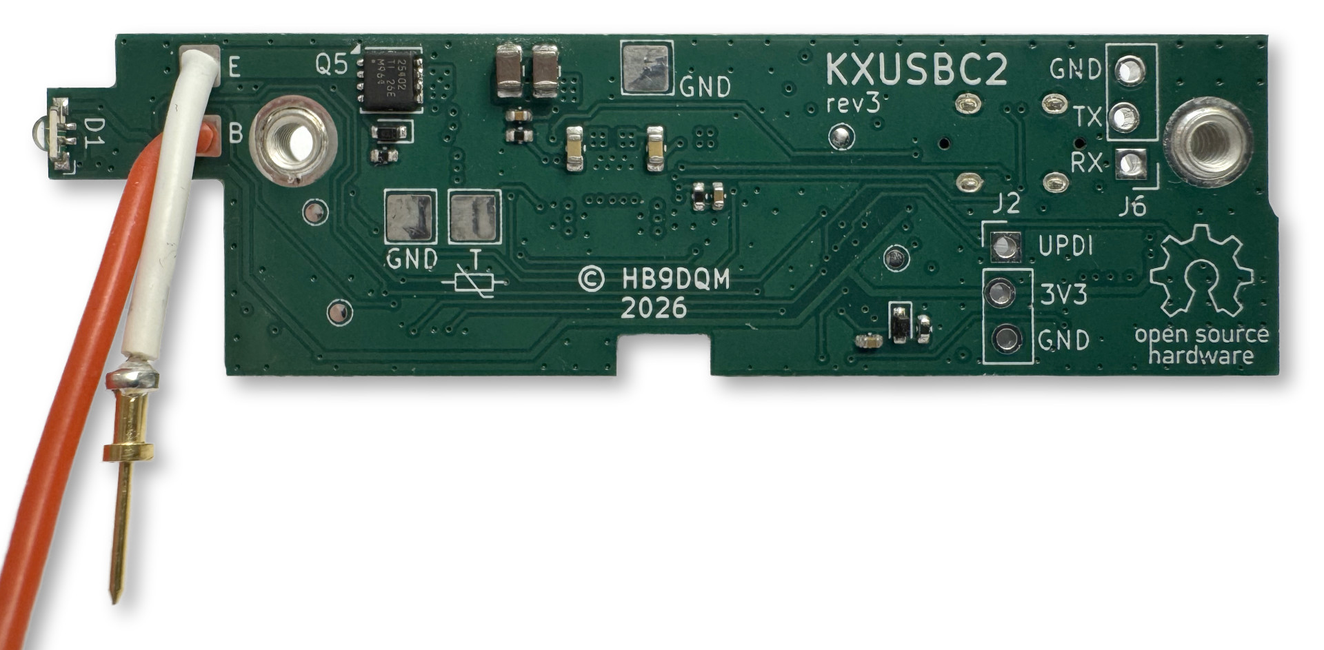
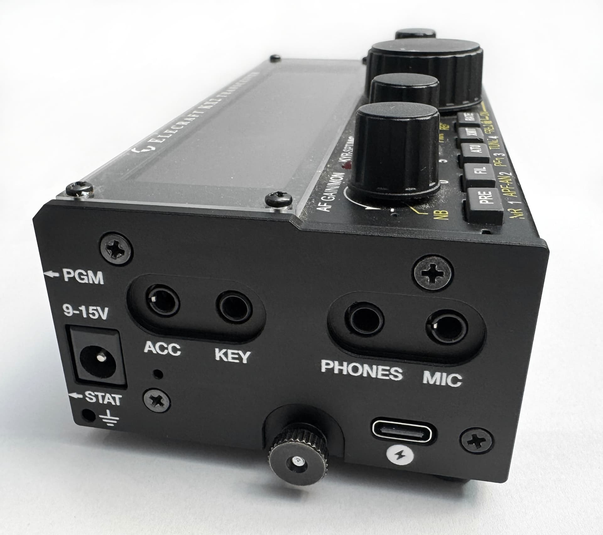
Here is how it looks installed in a KX2, with a custom CNC-machined aluminum side plate for the USB-C port opening:
Features
- Adds a bidirectional USB-C charging port to the KX2
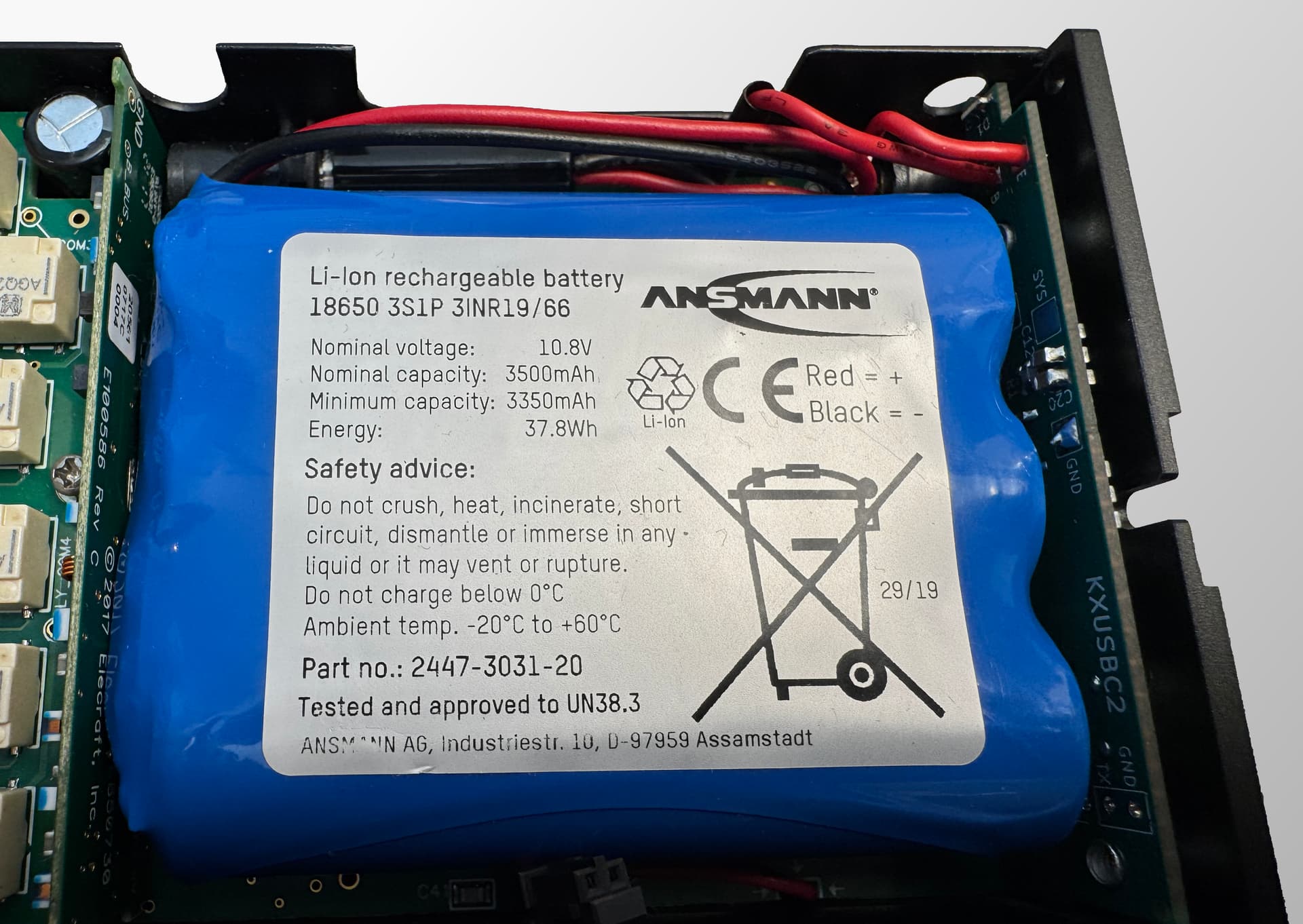
- Charges the internal 3S Li-Ion battery at up to 30 W
- Dual-Role Port (DRP/OTG): Can also charge an external device (phone, GPS, HT etc.) through the same USB-C port at up to 30 W (5…15 V)
- Dual input: can charge from USB-C or DC jack
- Supports PD 3.0, QC, BC1.2
- Real-Time Clock (RTC)
- RGB status LED and config button
- Battery temperature monitoring (with thermistor, optional)
- Battery voltage monitor in KX2 menu (like KXIBC2)
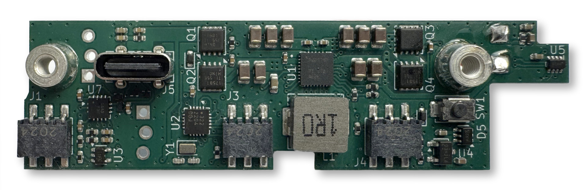
Tech details
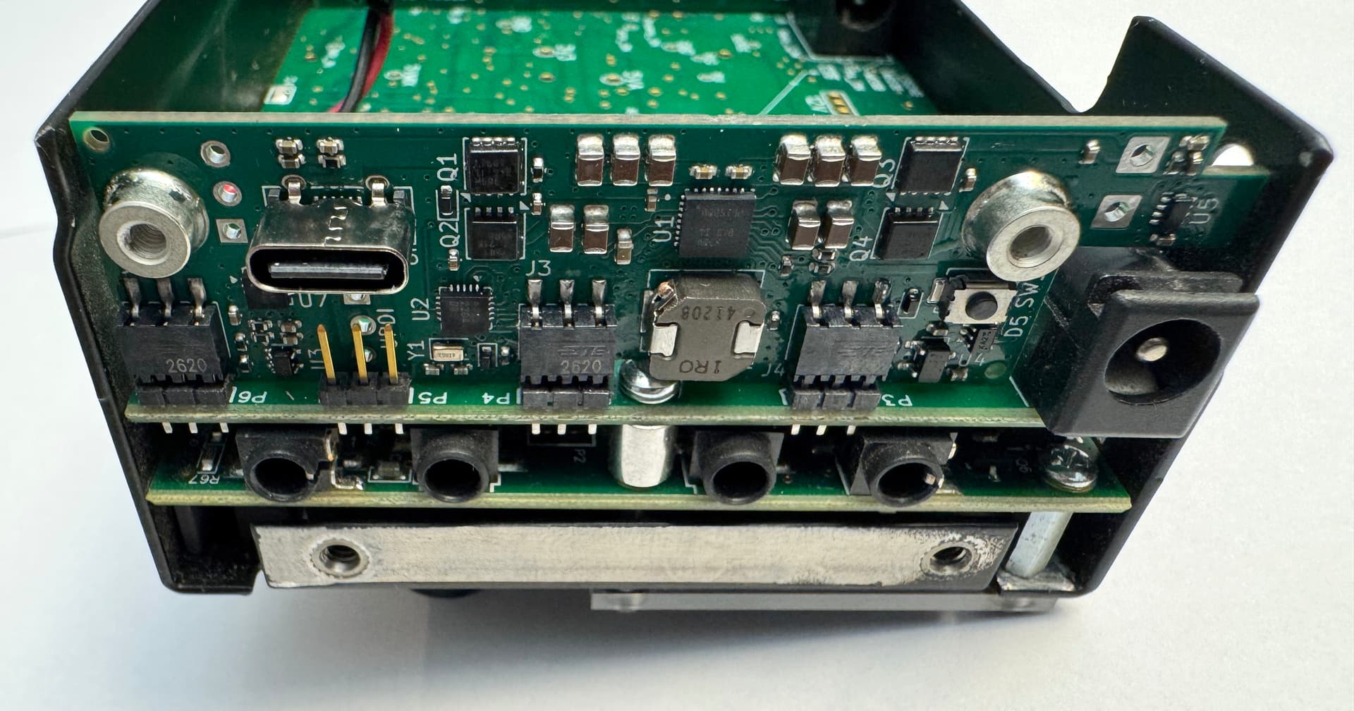
- BQ25792 buck-boost battery charger IC
- 1.5 MHz switching frequency
- Quad external power MOSFETs for input switching
- FUSB302B USB-C controller
- ATtiny3226 microcontroller
- Implements the PD protocol stack in firmware
- Current/voltage limits etc. configurable in EEPROM
- Config button for basic settings, trigger a PD role swap, reset
- UPDI debug/programming header
- Serial debug console header
- RTC emulated in MCU (SPI client), backed by crystal, with temperature compensation
- ~60 µA standby current
- 4-layer PCB
- Components on both sides (min. 0402)
- Replacement aluminum side panel, CNC milled, anodized and silkscreen printed, with USB-C and button pin hole
Cost
Most of the parts are relatively cheap, and the board was designed so it can be produced and assembled by low-cost services like JLCPCB. The total BOM at qty. 10 is around $30/pc. (including PCB production and assembly of both sides), plus $12/pc. for the CNC milled, anodized and silkscreen printed side panel.
Efficiency
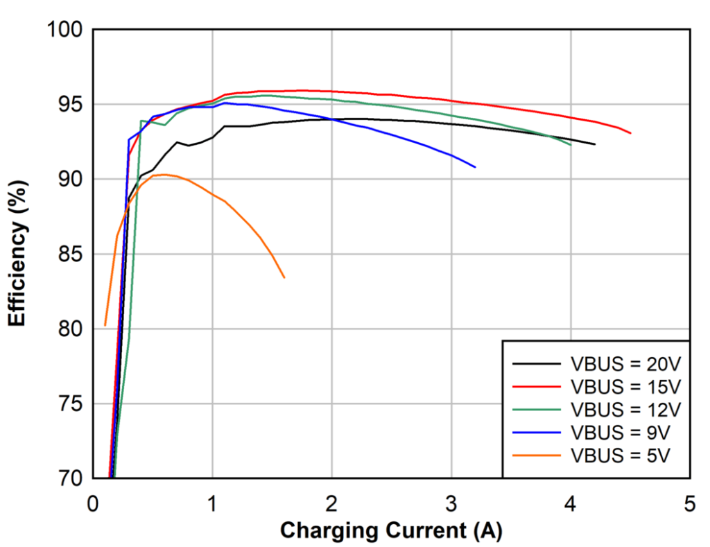
The graph above is taken from the BQ25792’s datasheet. I’ve done some casual measurements, both using the BQ25792’s internal ADC and shunts, and with external power meters, and they agree with the data in the graph: around 95% when charging from 15 V input, and between 85% and 90% from 5 V (depending on the current). There seems to be no problem dissipating the maximum possible loss of around 3 W through the side panel (thermal pad placed between the IC and the panel), and in any case, the charger IC has thermal regulation and shutdown.
QRM
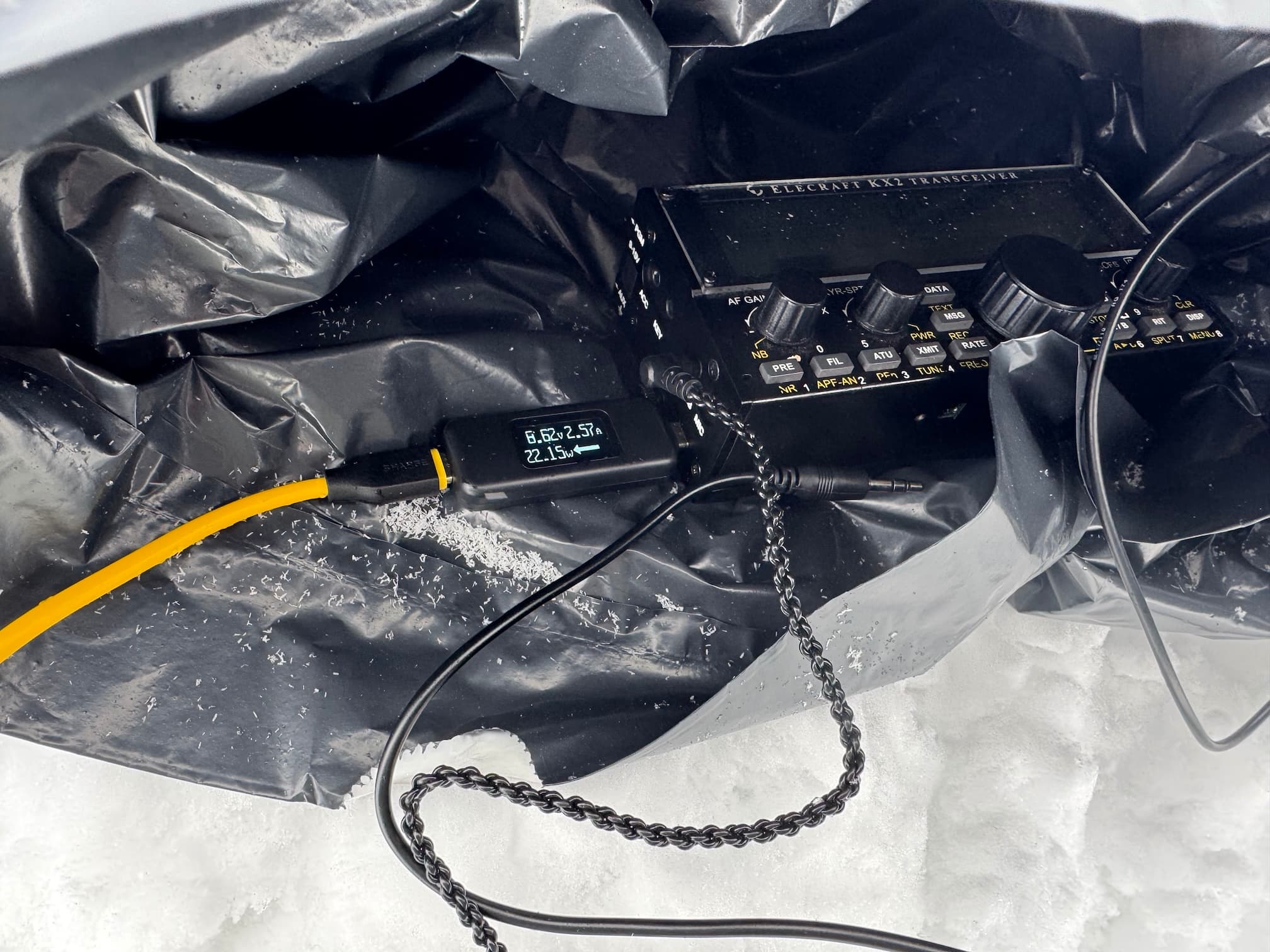
A charger like this is somewhat akin to a 10 W PA amplifying a 1.5 MHz square wave into a low-pass filter. Having that right inside a sensitive HF rig, and even electrically connected to it, one might expect QRM mayhem. I thought so too, and thus the firmware can automatically suspend charging while the KX2 is on, so one can still use an external power supply to power the KX2 while operating, without any QRM from the charger.
I did some lab testing, as well as real-life testing on a summit with an EFHW connected. The details can be read in the hardware notes. Short summary: some harmonics of the switching frequency can be heard while charging, with one falling into the 20m band, depending on temperature, and causing some QRM in a ~10 kHz bandwidth. Other than that, the noise floor went up to at most S2 (SSB bandwidth) on all amateur HF bands at maximum charging power (30 W). In the on-summit test, the background noise was much stronger on 20m and below, so no difference was heard whether the charger was on or not. Spurious emissions through the KX2’s antenna port were found to be ≤ -60 dBm. Operation seems to be possible without too much inconvenience even while charging.
Installation
Installing the KXUSBC2 is quite simple and similar to the procedure for the KXIBC2.
- Open the back of the KX2.
- Remove the original left side panel (4 screws).
- Plug the KXUSBC2 into the slot reserved for the KXIBC2/KXIO2.
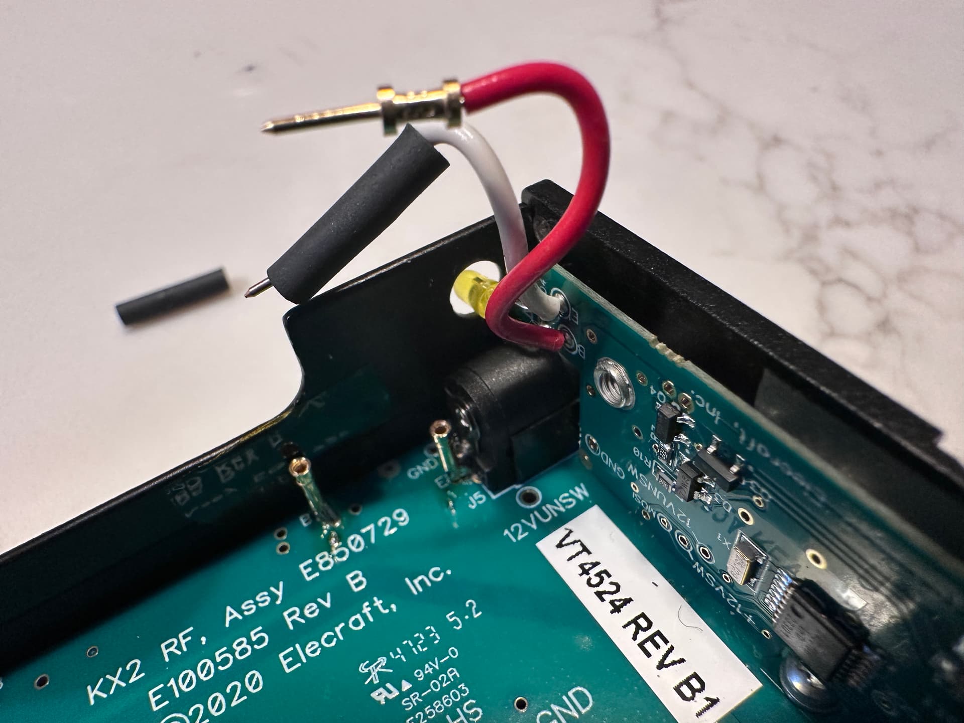
- Solder two wires from the E and B pads on the KX2 RF PCB to the KXUSBC2 (same procedure as for installing an official KXIBC2, see manual). If you have a KX2 with a factory installed KXIBC2, there should already be two pin sockets in place that you can simply plug into, no soldering required.
- Install the replacement left side panel (4 screws).
Instead of using a replacement side panel, an oblong USB-C hole can also be drilled into the original side panel.
Next steps
It’s been quite a journey to get to this point, with countless hours spent fiddling with the PCB layout, squeezing a full PD protocol stack into 32 KB flash, debugging obscure PD issues, or finding that one single bit deep down in a particular MCU or I²C register that had the wrong value at the wrong time. I learned a lot along the way, and having spent so much time delving into the intricacies of USB charging specifications and protocols, I have to say that I find it a miracle that modern USB charging works at all!
There are still some things to be done – minor hardware changes to deal with issues discovered during my testing, and completing the firmware (see issues in GitHub). Also, compatibility with more USB-C AC adapters and devices needs to be tested (list in Wiki).
I’m very happy with how it turned out; it is exactly what I wanted. Now the question is: does this solution spark anybody else’s interest? Before thinking about how everybody who wants a KXUSBC2 can get one, and how we would proceed with a beta test phase, I would like to gauge interest.
––– Polls –––
Would you like to beta test a KXUSBC2?
- Yes please!
- I don’t have a KX2.
- No thanks.
If you answered yes, how are your electronics/soldering skills?
 I’d need somebody to install it in my KX2 for me.
 If it’s assembled and ready to install (see above), I can handle it.
- Soldering a few SMD components (≥ 0603) is no problem for me.
- I can take the design and build it myself.
Can you program an AVR given a hex file, and obtain debug output from a TTL level serial port?
- No.
- I think I can figure it out.
- Yes, I have done such things before.
Design files
The schematic, PCB layout and firmware source code can be found on GitHub: GitHub - manuelkasper/kxusbc2: KXUSBC2 – Internal USB-C charger for the Elecraft KX2
73,
Manuel HB9DQM
Other, cheaper/easier ideas for USB-C on the KX2
One can find IP2369 based bidirectional USB-C charger PCBs for around $5 from China, e.g. on AliExpress (just search for IP2369). This chip can pump 45 W between a 2-6S LiPo/LiFePO and a USB-C PD port, in both directions. It is configurable both regarding maximum power and cell count/voltage using configuration resistors. I have investigated using this chip on my board, but found it hard to source, and all documentation is in Chinese only. It also seems to require relatively large inductors.
One simple idea would be to install a jumper wire between the E and B pad on the KX2 RF PCB (in the battery compartment), thus bypassing the reverse power blocking diodes (the KX2’s circuitry will still be protected against reverse polarity) – the same idea that @IN3JIB already had (DIY KX2 internal Charger - #5 by IN3JIB). This exposes the battery via the KX2’s external DC jack, so of course some care is needed regarding what is going to be attached there in the future. Then a IP2369 board in a small 3D printed case could be connected there when needed, and used to charge or discharge the internal battery as desired. Or one could attempt to mount the board directly inside the KX2, with the USB-C port sticking out.
Other threads that refer to KX2 charging
DIY KX2 internal Charger
USB-C PD power for the KX2
KX2 small/light charger
KX2 KXIBC2