Hi,
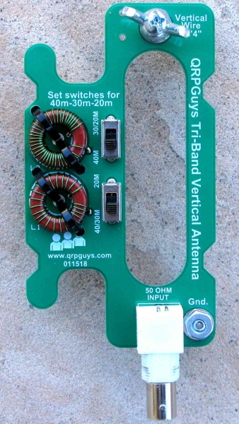
FYI: QRPguys is now producing a nice portable vertical antenna for 40-30-20m designed by Joe Everhart, N2CX:
Theoretically, it is a standard base-loaded vertical for 40 and 30m and a 1/4 wave vertical for 20m. The interesting thing is the clever mechanical design with a PCB that holds the coils and serves as a winder. Also, he uses toroids instead of air coils, and slide switches instead of the typical jumper wires as in my design.
Just ordered the kit. Shame the shipping is about the same as the cost of the antenna but for € 25 delivered to Europe, it’s not bad. It’ll make a nice companion to my 17 & 20m J-pole verticals using the same squid pole.
Oh why do they do this to me. I’ve only just received the superb qcx rig kit. Now they bring out a multiband vertical kit that’s cheap and looks good. Anyone know if they are any good?
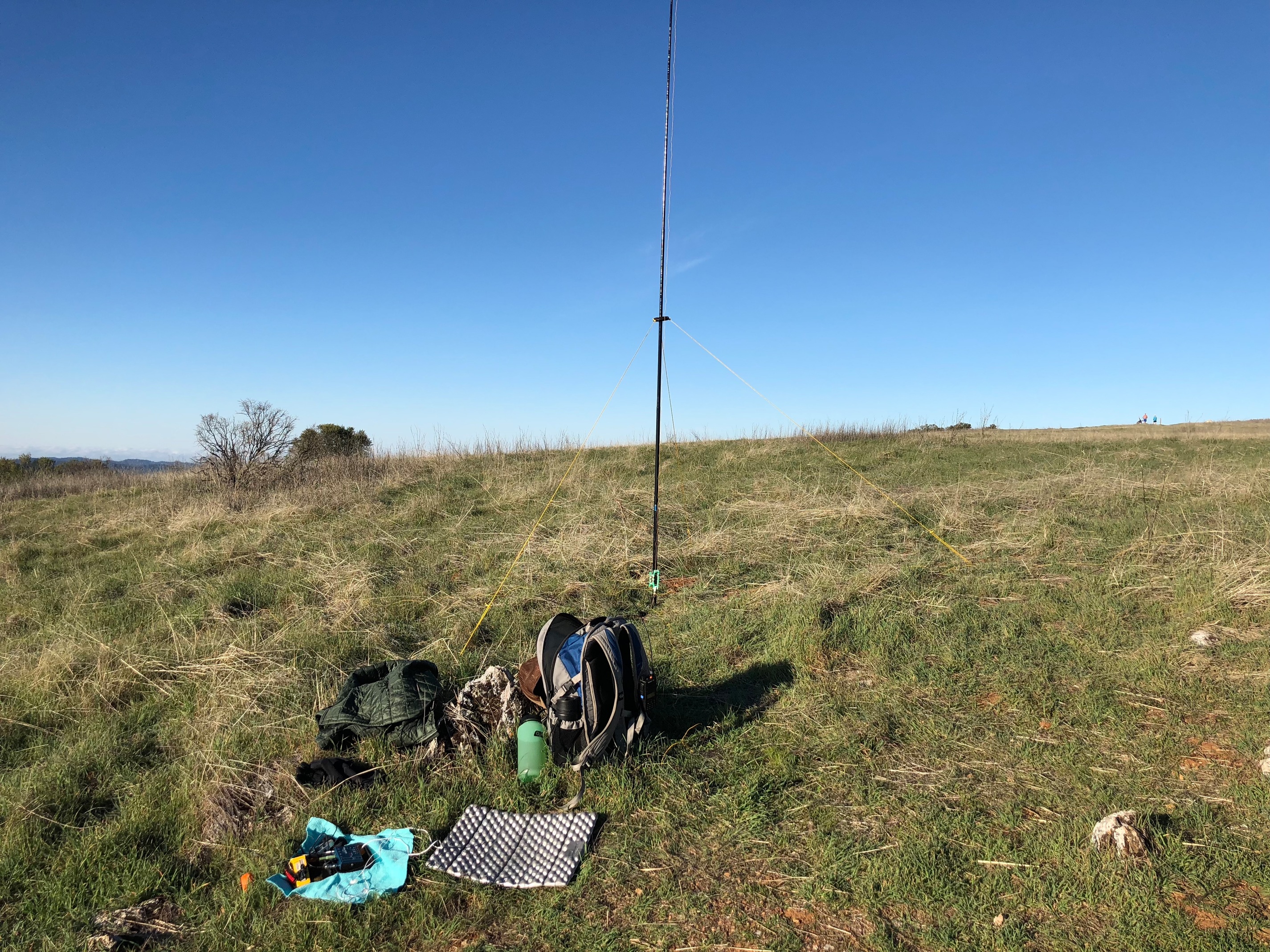
I just used this on my activation today. It performed quite well. Seemed like maybe it wasn’t quite as good as my full-size EFHW, but hard to tell the difference! Really quite impressed.
Hi Rex,
Can you tell me please what power the antenna is rated to handle? 5w / 10w / 15w etc.? Also do you need an ATU to use the antenna or does it present a 50 ohm load to the rig?
Hi Paul yes, I already downloaded that document. I didn’t see anything about the ATU comment in it though. I must have missed that.
Thanks.
I’ve sent an email off to the guys in any case as regards what power, my thoughts would be up to 20w “ought” to be OK.
I’ve also asked them if they think I’ll be able to alter the design to 20-40-60 as 30m is not of interest to me, not being a CW Op but 60m is interesting. As the frequency is going down, I expect the ferrites will still be OK, I only have to calculate and test the number of turns. Of course the antenna won’t be as efficient on 60m as on 40m but as always it’s a question of a compromise size over practicality.
Ed, Can’t see any reason why with the correct inductances the antenna wouldn’t work (or at least “tune up”!) on 60 too but wonder whether you might lose out on NVIS due to lower angle radiation? Or maybe DX is your goal
In principal this same antenna loading board can be used on a vertical or horizontal 1/4 wave whip, so the same PCB could be attached to a wire running horizontal to get NVIS if required.
Yes, but no mode is stated. 10 watts of RTTY, digital or even CW is going to be more of a load than SSB for example, so my 20w assumption was based on 20w PEP SSB. Looking at the components, I would say it should easily handle 20w PEP SSB. I’ll see when I get it and get it built.
It’s surprising how easy it is to miss stuff. I saw people questioning the power and thought “it’s there in black and white, 10W!!!”. The radiator length is clearly given as 17ft (5.18m in new money) but nowhere do they give the radial lengths. Bah! Useless docs! Well on the 5th reading I found it. I thought I was going mad till then.
10W keydown continuous power handling Ed. For unprocessed SSb speech that will be 30W.
Of course, we should now be questioning whether the coils should be 1/3 or 1/2 way up from the feed and whether the radials should be elevated…
Undoubtedly OK in this case, even with the small switches but generally care needed in such scaling - if the limiting factor is core dissipation, a reasonable assumption but if it’s peak voltage (or less likely peak current) you could end up with problems…
…and if so at what angle they should slope down at. Or how about using two of the units back to back to make a shortened dipole :-s
Aren’t antennas fun! yes we can talk about elevated radials and whether the feed should be part way up the mast but this design is for the board to sit at the bottom of the mast and hence the radials get laid out across the ground. That’s not to say it couldn’t be mounted further up the mast with it’s “Hi-Tech” mounting system (2 rubber bands).
The PDF does say “Use four 10’ counterpoise/ground wires attached to the ground wingnut” - so 10 foot radial wires. But I think you found that. How can this document be so “invisible” in places - that’s at least three of us that have missed things that are in the document, in black on white! Crazy.
My idea would be to cut radials to different lengths for each band the antenna works on, (three in this case) then tape them together for convenience and lay out the “bundle” in the opposite direction from where I hope to get contacts from.
one problem I always had with my vertical antenna prototypes is that the SWR varies significantly with the type of ground and the deployment. This might not be a problem for KX2/KX3 users with an integrated ATU, but for my MTRs, it is.
So far, I mostly used 1-2 elevated radials, sloping loosely from the feedpoint ca. 80 cm above ground. Tuned in my yard, it worked well on rocky summits. But on Texel island in PA land, it did not match without an ATU.
I used elevated radials for they are said to be way more efficient. Now I see that this new design uses relatively short ground radials.
The unreliability wrt SWR depending on the installation has reduced my interest in loaded verticals, despite the big advantages in terms of deployment on small summits.
Can anybody comment on whether the ground radials approach, taken in this new antenna, is less dependent on the type of soil?
What I am considering now is using a 12 step rotary switch and respective taps on the coils instead of two slide switches that shorten the entire coils, so that
you can mark the default positions for 20, 30, and 40m, but
you can still vary the inductance in order to optimize the SWR.
This will be a bit bulkier than the 2-slide-switch design, but way more flexible and more robust that a T1.
73 de Martin, DK3IT
PS: I might add a common-mode choke and a Dan Tayloe, N7VE SWR indicator to the design.
My vertical is similar to yours (Buddistick clone). The SWR is adjusted by altering the length of the single elevated radialpoise (is it a radial or a counterpoise?) The length is longer than needed for wet, boggy Scottish summits. From experience on a few hundred summits using it, I know whether the radialpoise needs to be shortened somewhat. For summits that are dry and volcanic (Madeira, Canary Isles) it needs shortening by about 10cms over the Scottish length. Gets the indicated SWR on an 817 back down to 0-2 blobs.
I am using a copy of Andy’s vertical. The “radialpoise” (lovely name!) is on a seperate winder, the wire is marked with red tape at the tuning points, and when necessary I adjust the tuning by changing the length that is unwound. This quickly results in a good match every time I deploy it. Last time I used it on 20m SSB my third call was from the USA so it seems to work well.