SOTA Vertical Antenna for 40-30-20m

Hi,

I had promised to provide more details on my most recent antenna project for SOTA, which is a three-band vertical with a loading coil at the base.

Background: I am a happy user of the 3-band EFHW with traps designed by Heinz, HB9BCB, but on some summits, the ca. 16 m of wire are difficult to deploy. On crowded summits (like skitouring in winter), you risk to annoy people by an inverted vee of that size right on the summit (and they might even take down parts of your antenna without asking). On a small summit, it can be difficult to actually get to the ends of the inverted vee.

Approach: I wanted to try a vertical that is more compact than the EFHW, yet way more efficient than e.g. an ATX1080 or Miracle Whip.

So I decided to take

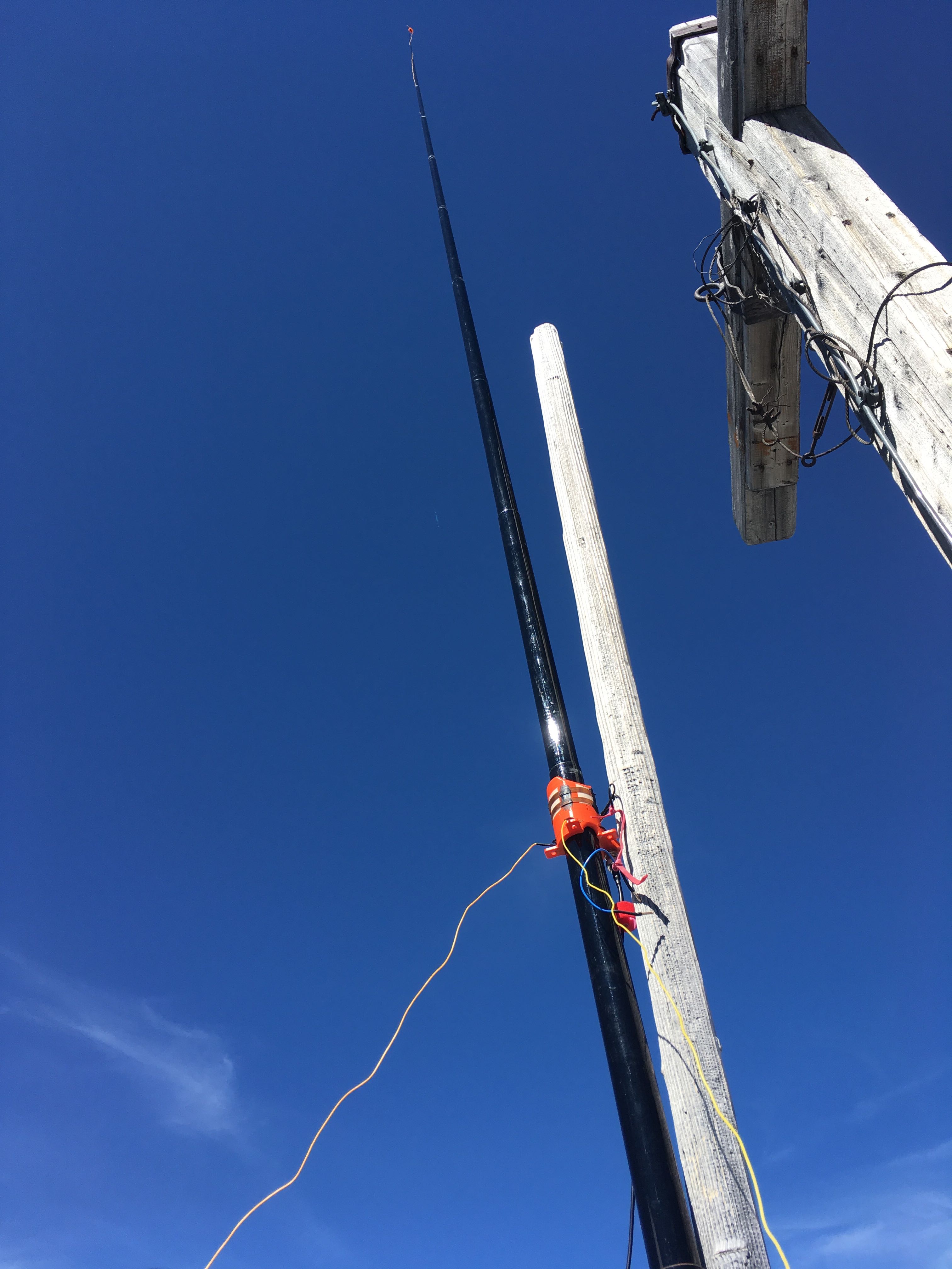
  1. a Lambdahalbe 6m mast and
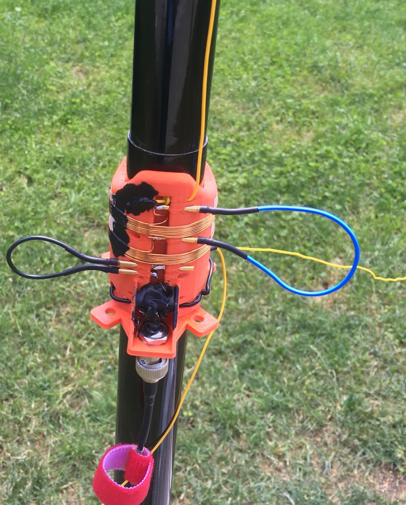
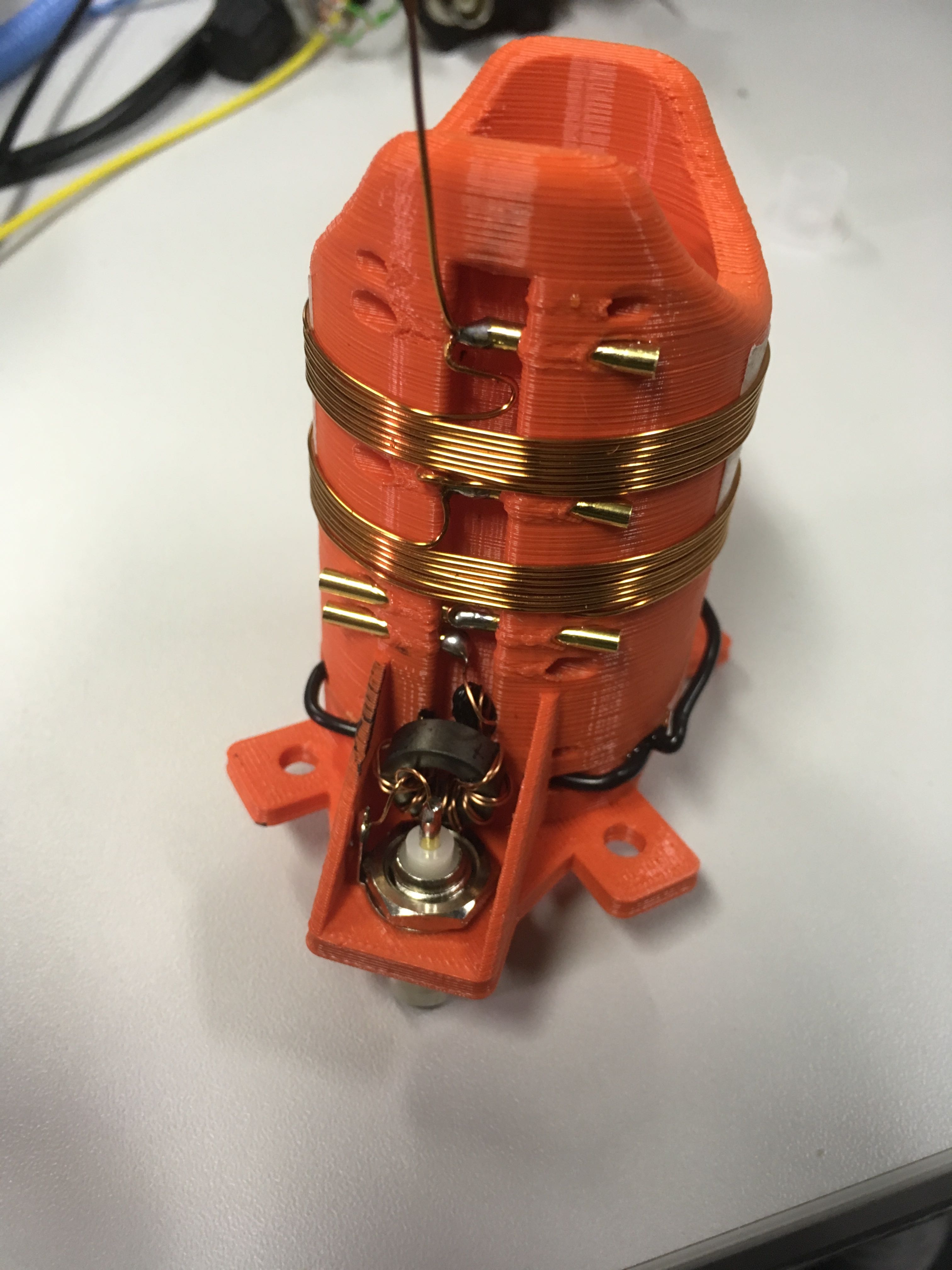
  2. a taped loading coil at the base, which also serves as a guying kit.

The coil is put ON the mast (which shoud be GfK in this case in order to avoid stray capacitance).

One to three radials are tuned to length and the excess wire is wound up on SotaBeams mini winders.

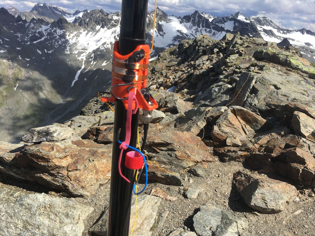
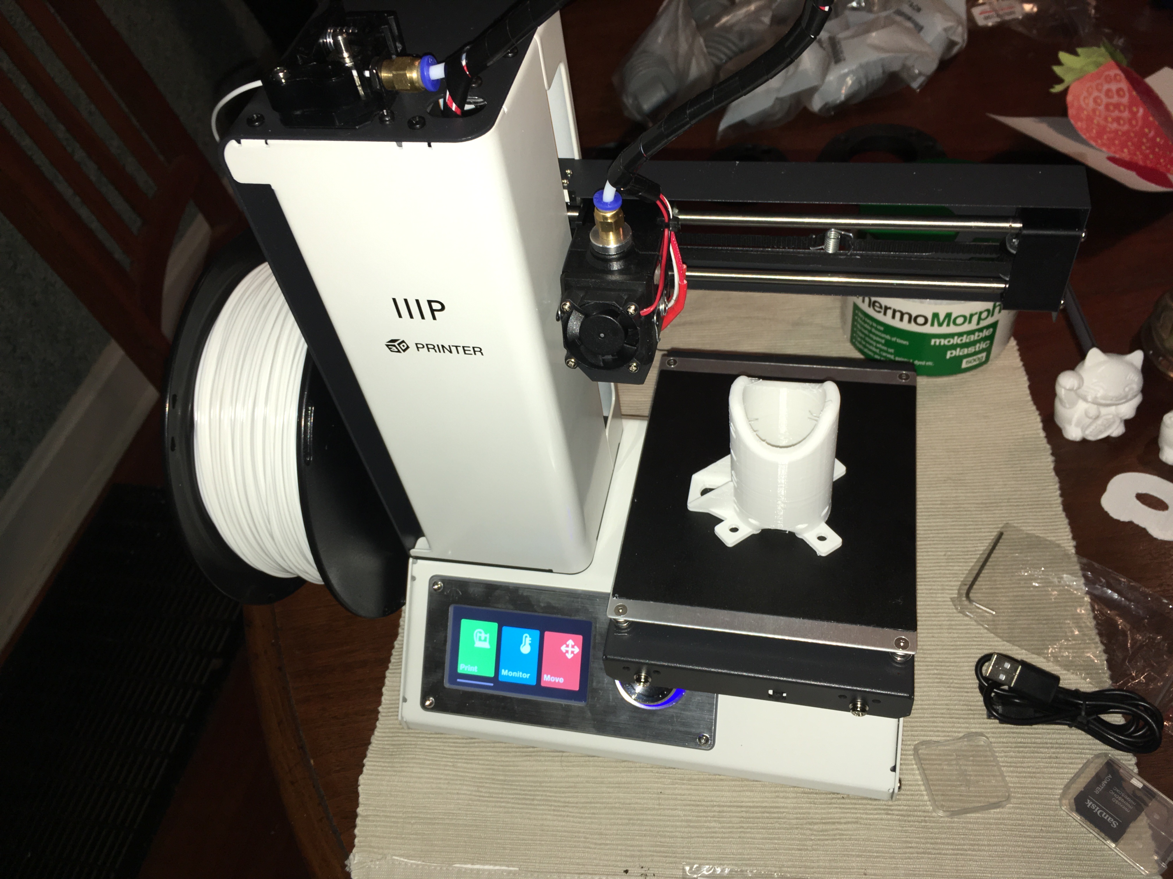
Here are a few pictures of the solution. So far, it worked pretty well. I will publish the files for 3D printing on Thingiverse soon.

Band change is relatively easy: You get in the radial or radials and unwind/wind the wire to the respective length (and fix it with rubber band), and you change position of 2mm plugs that shorten unneeded parts of the loading coil.
Basically, the whole antenna is a giant ATX1080, with the difference that the radiator is ca 5m long instead of 127 cm (or even shorter) in the case of the ATX1080.

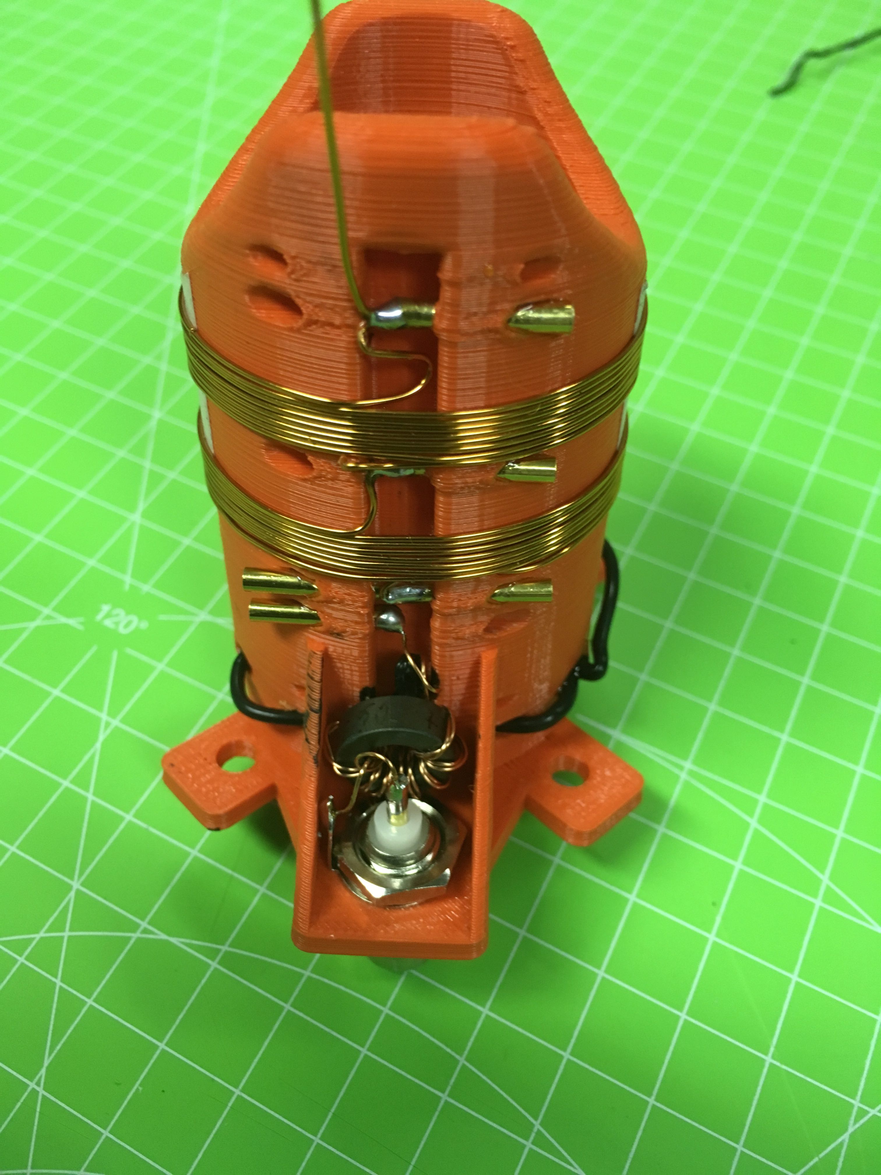
The loading coil is from 0.63 mm enamel wire. For 20m, you need 0 - 2 turns, for 30m ca. 8 and for 40 m ca. 16 turns on the 3D-printed coil body from PLA.

I also included a small balun (FT50-43 + 11 turns of twisted enamel wire) in order to block problems resulting from suboptimal radials deployment.

I know that a loading coil towards the middle of the radiator would be more efficient, but in this case, I started what is physically feasible and good from the perspective of handling, and learn how far I would get.

The antenna is 227 g including a bag, and the coil body also serves as a wire winder.

73 de Martin, DK3IT

9 Likes

Here are the 3D files if you want to make one for yourself:

Martin

1 Like

Hi Martin,

Thanks for sharing!

I don’t understand why you need a balun for an unsymetrical antenna fed with coax cable. What are the “problems resulting from suboptimal radials deployment”?

73 Heinz, OE5EEP

Martin,

+1 for publishing the design
+1 for making the 3d files open

This is very similar to the 3 band antenna I described which itself is my lightweight SOTA build of a Buddistick. Mine used a shorter top section with about 4/5th radiator - coil - 1/5th raditaor before the feed point and just a single radial/counterpoise. Like yours, you alter the tap and the radial/counterpoise length. I have about 3m of RG58 to the FT817 and l’m sure the coax outer is acting as more counterpoise at times.

I may have to try your version as I have a 6m mast that is unused, my vertical fits on a 5m mast. I think the 5m version will not be very good on 40m, but it does work on 30m but is still a bit of a cloud warmer.

Have you tried it with just a single radial? You may find almost no discernible change vs. a 3 radial design.

Now to find someone local with a 3d printer …

The question about the Balun is legitimate, but I suspect Martin wanted to build a common mode choke what would undoubtedly be useful (e.g. 9-12 turns of RG174 on a ferrite core of suitable diameter).

It’s posts like this that highlight the value of the SOTA reflector community. You’ve constructed the solution to the mess that I cobble together at the base of my mast. You have a very neat set-up. Aside from me being too busy in my non-SOTA life to be working on SOTA projects, I’d like to make this one. Thanks so much for the 3D files.

Hi Heinz,
Heinz (HB9BCB) is right - sorry for sloppy terminology, it is a common mode choke, built as follows:

  1. Ca. 30 cm of enamel wire twisted so that it has an impedance of close to 50 Ohm
  2. 11 turns through an FT50-43 toroid.
  3. One side of the two twisted wires goes into the BNC / feedline connector.
  4. The other ends go into the radiator and the radial or radials.

As far as I understand, common-mode chokes are useful because of the varying quality of ground. While it might not harm to have part of the short coax braid be part of the radials in a SOTA environment, it makes, as far as I understand, the SWR be more varying with antenna deployment and ground characteristics. At least that was my motivation for including it.

Richard from SOTAbeams calls this a balun in http://www.sotabeams.co.uk/content/Pico%20Balun%20Instructions.pdf

But as far as I understand from these instructions, his Pico Balun is a Common Mode Choke, at least in the proposed wiring.

Each arm of my twisted wire has an inductance of ca 103uH, which gives the following reactances for common-mode currents:

40m: 9 k
30m: 6.5k
20m: 5 k

I am a real freshmen in this, but as far as I understand, that are reasonable values for this purpose.

If I find the time, I will measure the attenuation of the choke and post the results in here.

Martin

1 Like

By the way, if I find the time, I plan the following improvements and investigations:

  1. For 20m, a small loading coil (ca. 0.2 uH) would improve the matching. I might try to tap the 30m coil after 1 - 2 turns for that. The bridge on the left was meant to allow including a fixed or variable capacitor, because I had initially assumed that the radiator would be a bit too long for 20m, which I wanted to compensate for.
  2. The current coils are pretty densely wound; this likely introduces stray capacitance. I am uncertain of whether this is a problem and how to best measure it. The ATX 1080 uses much wider spacing for the coils. But on the other hand, the loading coil would get pretty bulky if I wanted e.g. 5 mm spacing in between turns.
  3. I had thought of a mechanism to attach the jumper wire to the coil in order to not loose it but forgot it in this version.

As for the number of radials: So far, I mostly used it with two radials. I suspect one radial will be very similar in terms of performance. The advantage of having two is that you have a spare one in case the small plugs break etc. In worst case, they can also be used to improvise an antenna with a T1 tuner or Z-Match.

Performance-wise, I think the antenna is about 25 - 40 % of the 3-Band EFHW described by Heinz, HB9BCB.
I got a typical mix of 559/579/599 on 40m during my activations of OE/VB-001 (Großer Piz Buin) and OE/TI-035 (Dreiländerspitze). On RBN, SNRs of 10 - 14 dB are frequent, despite the bad CONDX at the moment. I will soon have a 2nd WRSPlite and will be able to make a more systematic comparison.

One must say that it is a pure SOTA antenna - near buildings etc. it picks up a lot of noise. But after all, this is why we head to the mountains, don’t we?

Martin

Just done - the insertion loss due to the choke is in the 0.6 - 0.8 dB region. Not ideal; maybe I should rebuilt it. But on the other hand, 0.8 dB is just 20 % loss.

Insertion loss for current on the outside of the cable, or the inside?

Both. This is measured with the following setup:

Generator Signal ------~~~~~~~~-------- Detector Signal
                       ========
Generator GND    ------~~~~~~~~-------- Detector GND

The choke is 11 turns of twisted enamel wire on a T50-43 core.

Oh, sorry, I was thinking of coaxial cables.

in your measurement setup you would want minimum losses, i think.

73 Andrew VK1DA VK2UH

Yes - I assume the relatively high loss in the current balun / choke is either due to

  • an impedance mismatch of the twisted enamel wire wrt 50 ohms
  • stray capacitance
  • resistive losses, e.g. caused by defects in the isolation cause by winding the wire to tightly around the toroid.

Will do a new one and measure that before assembly.

Martin

FYI:

  1. I found that the antenna is somewhat dependent on the type of soil. For instance, on sandy soil on a PA island recently, I was unable to achieve an acceptable SWR; it was all too low impedance. My next version will
    a) put the coil higher (ca. 1.6 - 2m above ground) in order to improve efficiency
    b) combine it with a T1 (or other) tuner to balance out the variations of the deployment.
    This will still be much more efficient than just using the T1 for an up-and-outer, because my loading coil has a better Q than the tiny T1.

  2. On Wednesday, I managed to work Japan with 5W in CW from Crete on 30m and got 559 - 579 and could hear the station with bold 599+. My best DX so far! Of course, I was lucky to find a sweet spot in the current propagation turmoil.

Cheers

Martin

I think this is a great project Martin - many activators would benefit from such an antenna, especially in these times of lower sunspots where the higher bands aren’t so important. I know many summits with dense vegetation that really require a vertical antenna be used.

I lack the ability to make such an intricate coil form. But I may try to make the base loading coil form out of pvc and fiberglass and perhaps use an alligator clip to adjust the tap.

Is there an easy way to estimate how many coil turns and coil diameter will give the proper loading? What is the math behind how much inductance is needed for the element length to make it resonant and how much inductance is provided by the coil turns/diameter?

Thanks & 73,
Barry N1EU

I found answers to my questions :slight_smile:
http://www.66pacific.com/calculators/coil-shortened-vertical-antenna-calculator.aspx

Whatever you build, you should keep an eye on TANSTAAFL
http://www.ad5x.com/images/Presentations/Antenna%20Efficiency.pdf

This solution here takes into account TANSTAAFL but may be a bit too heavy for SOTA usage (on real mountains)
http://www.ad5x.com/images/Articles/VerticalRevH.pdf

Heinz, I’m talking essentially about a full size quarter wave vertical for 20M with a low loss loading coil for 30M and 40M, which I would place as high as I can reach. I think it would be a fairly efficient radiator, esp on 20M and 30M.

Hi Barry, Heinz:

The TANSTAAFL slides by AD5X actually inspired me to go for a version 2 of my antenna approach, putting the loading coil towards the middle of the radiator, 1.6 - 2m above ground (so still easy to reach from the ground for changing jumpers.

The entire rationale behind my antenna design is that I want to use a high-Q loading coil for the biggest part of the matching, and the (T1) tuner coils only for minimal matching caused by deployment and soil variations.

I expect my approach to be much more efficient than to lat the T1 tuner do all the matching, because of

  1. the higher Q and
  2. the higher position

of the loading coil.

My first design has the loading coil at the base, but ca. 1m above ground.

It work surprisingly well, as ambiguous as any such statement is. But I made a CW contact to Japan on 30m two weeks ago with it, getting 559 and 579 from my 5 W station. 10,000km is not to bad for a simple 6 m mast at the beach of the Mediterranean Sea :wink:

Since I am now a proud owner of two WSPRlites, I will soon be able to add a more systematic performance comparison to the table.

Martin

I previously hadn’t considered buying 3d printing equipment, however Cliff N4CCB suggested this $200 Printer.