The biggest difference is ground loss. You can try switching a model to “perfect ground” or “free space” and see how much that changes the efficiency.
But many common modeling programs only report the resulting ionospheric propagation. That means that any power radiated as ground wave is treated as lost power in the efficiency calculation. For many contacts that is a reasonable assumption, especially for distances over 50km on the higher HF bands.
Of course, by definition, SOTA activators probably are not going to be operating from the infinite flat ground assumed by modeling programs. As Les Moxon G6XN pointed out, operating from sloping ground a little ways down from a summit can give good low angle radiation (at least in the direction down the slope) from horizontal dipoles at relatively low heights. Similarly, the very center of a gently rounded hilltop may not be the optimum spot for HF (or, in some cases, even VHF).
So, if you aren’t rushing to get off the summit due to snow / lightning / midges / etc., put up two antennas and compare the coverage on RBN. That probably gives you a more accurate idea of how well they actually work (at least on that summit) than trying to model the environment.
That’s a key argument. A vertical antenna on a high, rocky summit radiates very flatly, making it certainly the best choice.
In this context, I also think of the good results achieved by very short telescopic antennas like the Elecraft AX1. The rocky ground acts as an insulator, and the counterweight also radiates significantly.
Predicting the radiation patterns from an antenna on a hilltop is not a trivial task. Rather than a flat ground underneath, there are reflections off the hillside, the valley below, the next range of hills, and even topology to the sides of the path. All of those can cause lobes and nulls at angles that aren’t predicted by modeling programs that don’t take the topology into account.
For low angle radiation, often the best approach is to put the antenna at the top of a steep drop-off, and hope for the best. That might not necessarily be the highest point. If you have a portable whip antenna of some sort, you can walk around the activation zone and see where signals from the target area seem to be strongest. It probably makes less of a difference for more local contacts.
When looking at a vertical radiation pattern, don’t worry too much about the angle of maximum radiation. Instead, look at the actual radiated signal strength at the vertical angle required for the path you want to cover. It’s not uncommon for a dipole to have a higher angle of maximum radiation than a vertical, but still have a stronger signal than a vertical at the latter’s angle of maximum radiation.
Also, for those modeling antennas be aware that the ground coefficients change with frequency (and sometimes with temperature). The “standard” values are for the AM broadcast band, around 1 MHz. Brian Beezley, K6STI, has an excellent page that explains what coefficients to use for the HF ham bands. (And how to measure it at your site, although most activators might decide to skip that step unless they intend to return to a particular summit regularly.)
Interesting link, thanks Dale. I managed to follow up the links Brian K6STI used to generate his charts and tables. As you say, the “standard” ARRL values for ground coefficients are indeed for the broadcast AM bands, which is something I was not aware of, and which the ARRL Antenna Handbook does not mention (ref. ARRL Antenna Handbook 20th Ed., p.3-13). This document makes this clear:
see Table B, p. 34.
I shall be making some efforts to perhaps incorporate the results listed by Brian in my antenna modelling site. I have had email conversations with him in the past, and note that he is very knowledgable in this area.
EDIT: due to one or two technical constraints imposed by the NEC engine, I’ve decided not to incorporate the results listed by Brian in my antenna modelling site.
After a week away from the SOTA reflector the original question has created some chat - which is good.
Going back the question about vertical antenna. I ended up going down the MM0EFI antenna route and after a bit of trimming got the SWR down.
First hit was 5/5 into HB9 land. Certainly more compact than my 20/40m linked dipole.
While this discussion leaned toward the theoretical, it motivated me to build a vertical antenna, so I wanted to share my experience with the group. I made a 1/4 wave vertical with three sloping radials for the 15-meter band—slightly off-topic, I know. I used the dimensions from portable-antennas - Vertical antenna designer. The wires are military telephone wires with PE insulation. Initially, the antenna resonated a bit low, but after adjusting (shortening the radials once and the radiator twice), I got it tuned perfectly. The SWR minimum is 1.1:1 at 21.025 MHz, and the SWR is below 2 from 20.180 to 21.720 MHz.
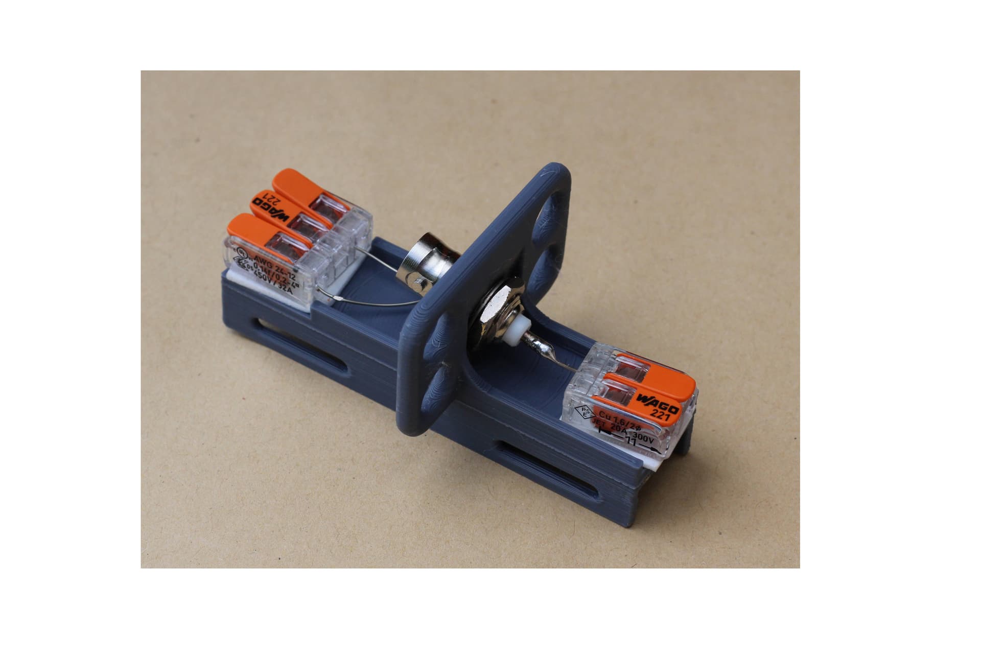
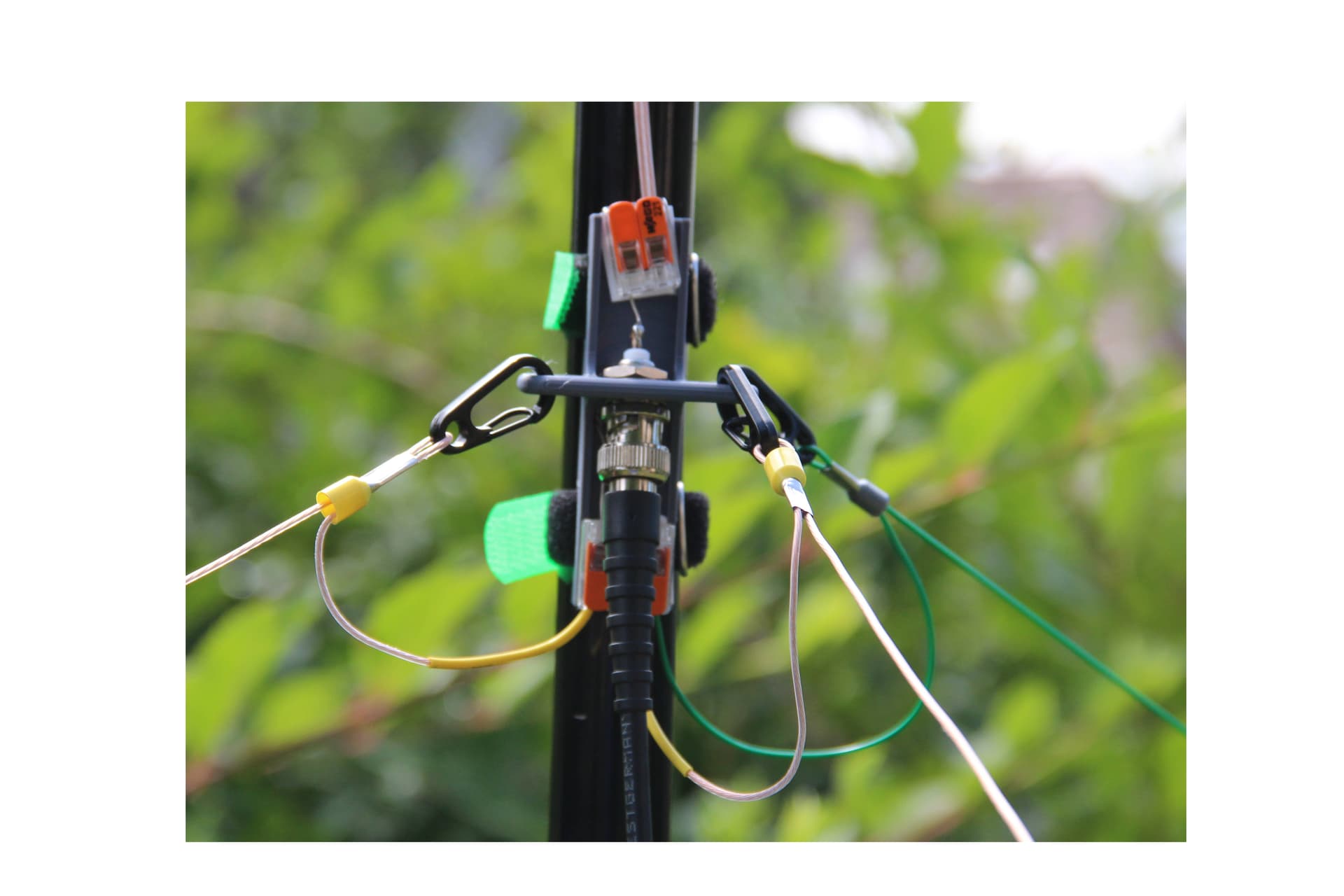
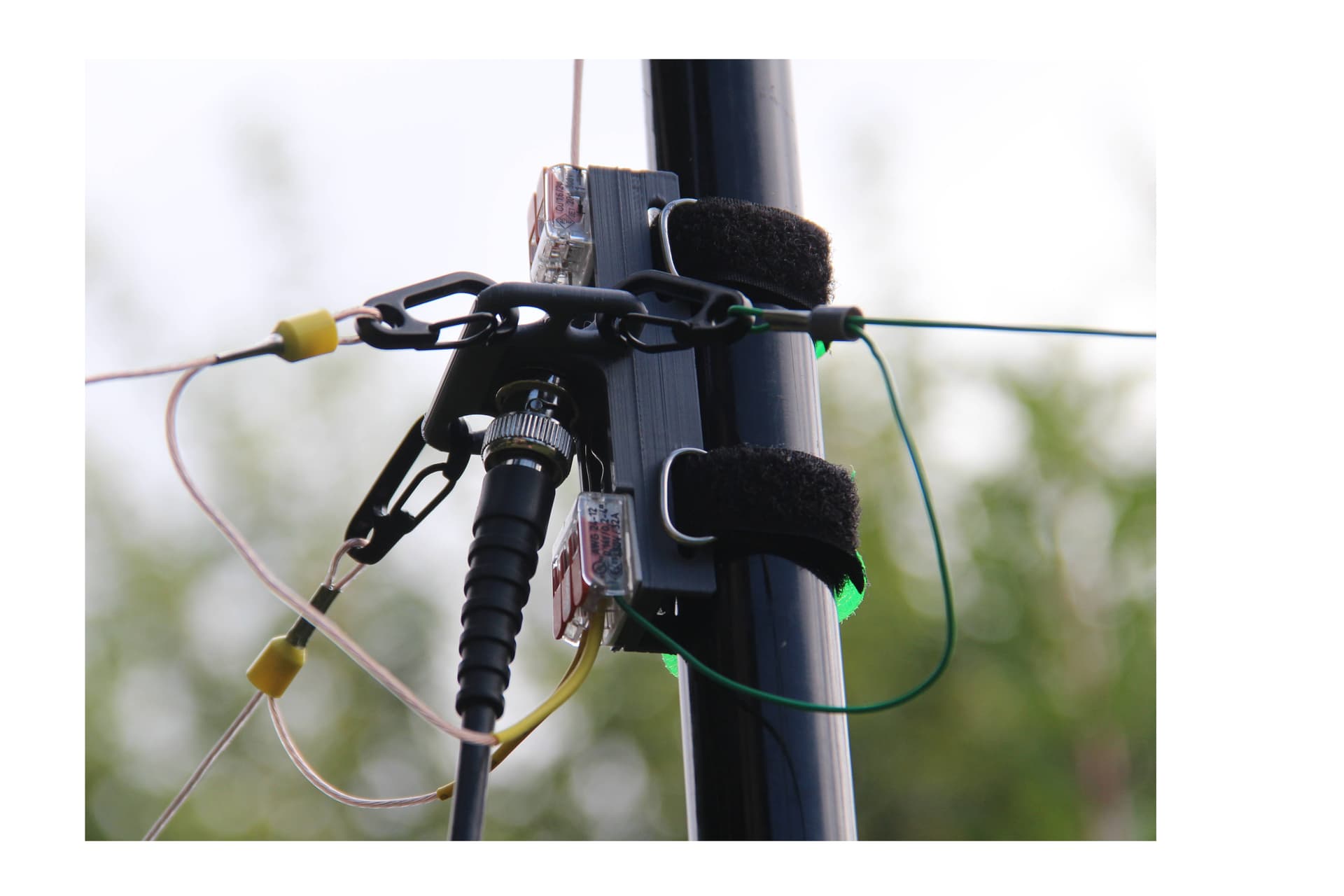
As an obsessed 3D designer, I built a custom centerpiece that holds a BNC jack and uses two WAGO clamps, one for the radiator and one for the radials. It attaches to a telescoping pole using two Velcro straps. This setup requires no tools and avoids small, easy-to-lose parts during field use. I’m curious how others have approached this. The radial connections are strong enough to act as guy wires and support the mast upright.
I still want to make a few refinements to this design and will publish it on Printables soon.
Crazy guy ! Seriously, though, I love how you have designed the connectors/connections to the radials, and the coax to the block. When I built one of these, it was a hotch-potch mess (which nonetheless worked), and I had in my mind some kind of block connector for the radials, but had never heard of WAGO clamps. Nice job!