Jut a short note here for any chaser looking for a good antenna for 40m and 20m. I suppose it could be used on an activation as well however it would need a flat topped summit and some effort to install.
The 40m horizontal loop, or more normally a square of 11m x 11m, for a wire antenna performs very well. In a real world comparison with my two element tri-band mini-beam both anntennas at 7m AGL, the reception is identical from both antennas on 20m. The beam does allow the nulling out of some QRM however costs a lot more and needs a solid mast and rotator.
The fact is that you have two wavelengths of wire on 20m up in the air and that seems to perform remarkably well.
For those interested in building a 40m horizontal loop antenna, using just 4 x 7m squid poles, some gardening wire a length of 75 ohm coax and some small pieces of plastic tube, I wrote an article in the CCARC “Smoke Signals” magazine a couple of years ago - for anyone interested, I can post the URL to the PDF file here.
Here you go - lucky I checked, the club has moved the document off the website into dropbox. Don’t worry you don’t have to join Dropbox - just close that popup window and you’ll get to the magazine, my article starts on page 4.
Hi Ed.
Brilliant aerial the 40mtr full wave horizontal loop,
I have used one for years now to the design from Mike G4HOL (now resident in Spain) mine is 141ft 6ins of top wire in a square fed with a random length of 300ohm ribbon feeder to one corner and down to the shack directly in to a 4to1 balun in the atu.
By using ribbon feeder it allows you to tune on all bands from 10mtrs to 40mtrs.
I have not tried it as I have been happy with the performance of this one but if you want it dedicated to 40 mtrs and possibly 20mtrs feeding it with 75ohm twin may be an option being a lot quieter from feeder noise on rx.
73 Don G0RQL
Hi Don,
The antenna works well on 40, 20, 15 and 10m and does “work” but not so well, on 80m (yes 80m believe it or not), 17 and 12m with an ATU. In theory the 75 ohm section should be different for each band, but for the main bands, using one cut for 40m seems to work fine. I must try cutting one for 20m and see if the performance improves. Today I tested again and listening to a STA activator in Spain the signal was the same strength on the loop as with the 2el mini-beam pointing at the station, but the noise level was lower on the loop.
My understanding is that the feed point impedence is around 100 ohms, so if one could get 100 ohm ribbon cable and a 2:1 balun in the shack, that may be the best solution, but then doesn’t the ribbon cable radiate as well?
For someone looking for a cheap, easy to build antenna that performs even at relatively low heights, the full wavelength loop or the delta loop are both worth considering. If I raised the loop here to 10m AGL I’m sure it will out perform the beam!
Feel free to take a look at the other CCARC Smoke Signals magazines here : http://www.ccarc.org.au/wp/smoke-signals/ and please send the editor Leonie an email to smokesignalseditor@fsparker.com.au telling her that you like the magazine - it’d make her day! Leonie (VK2LCP and her husband Fred VK2FSP) have been procing the quarterly magazine for many years and sometimes it can be a thankless task, chasing people for input.
Now showing a lack of knowledge in this area. If the ribbon cable is balanced, why is a BALUN (balanced to Un-Balanced) needed at the shack end? The rig is a balanced connector, right? I know there are UNUN’s but in this case a “BALBAL” would be needed. I’ve never heard of one of those. As the 75 ohm coax stub is a balanced cable and it needs to be a specific length, wouldn’t the ribbon cable also need to be a quarter wave at its velocity factor?
For chasing purposes I am using a 40m long horizontal loop for the 40m band and compared the performance with a monoband dipol and an endfed, both 20 m long. The loop and the other antennas are mounted between 6m and 12 m above ground.
Since I had a feeling that I can not hear some chasers on 40m because of the radiation characteristics of the loop, I thought I try something different. But the loop is superior in almost all cases. There is a gain of one and often even twoS-units during reception and also transmission.
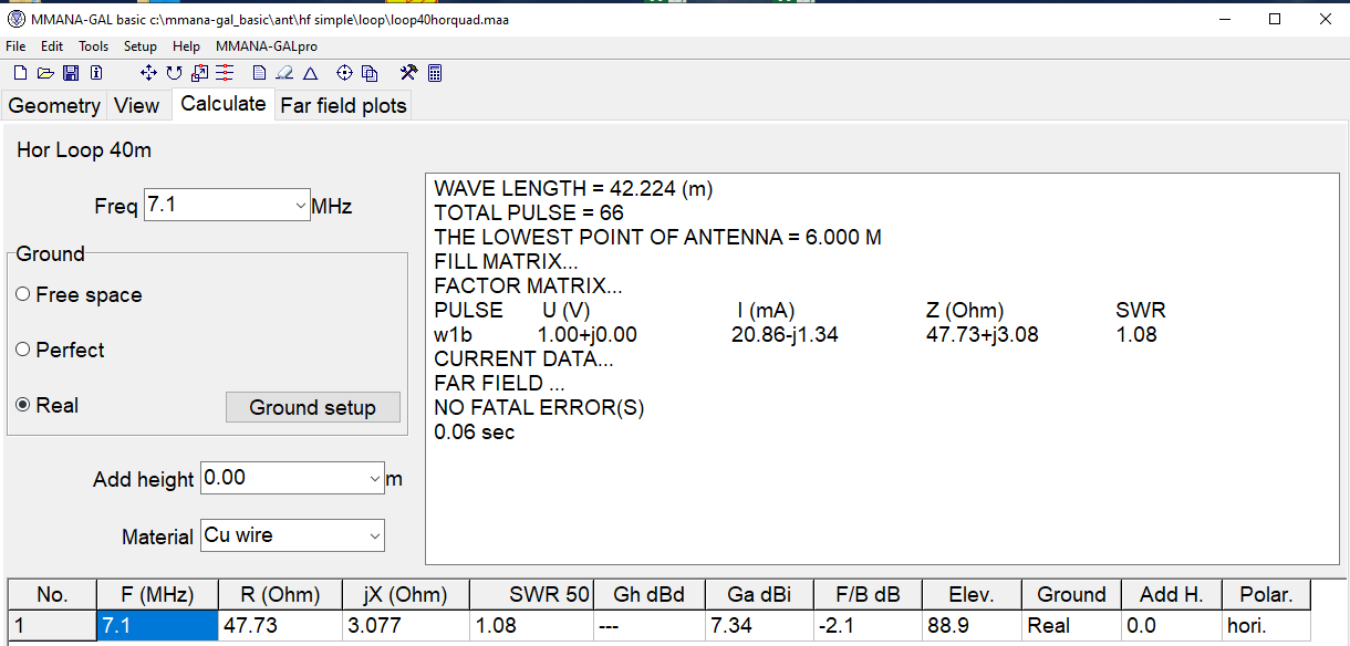
The loop is fed with a Koax and a current balun since the actual loop impedance at the the low hight is only 50 Ohm. This result can be also seen in a simulation. Theoretically the impedance should be around 100 Ohm, as Ed stated above. The simulation says, this ist true at a height above 20 m.
So I am still very happy with my loop, even when I am not able to hear some of the activators. That’s how it is.
Hi Peter, my loop at 8m AGL gives a measured impedance at the feed point of 150 Ohms, the last time I checked it. The loop is NOT a good NVIS antenna as it has limited high angle radiation and reception. It’s better with DX. It is also a very quiet antenna not being as affected by local electrical noise compared to a dipole or vertical.
“Horses for courses” - for SOTA one needs a short range (NVIS) and a longer range antenna and ideally antennas that are multi-band.
Did you mesure the 150 Ohm on 40m or 20m ?
Depending on propagation, my loop performs well within distances of 400 to 800 km which is quite ok I think. I have not tried a real NVIS antenna.
150 Ohm was measured on 40m. I think I simply ran a length of coax from the feedpoint to the analyser while adjusting the overall length for resonance, before then fitting the Q-section (1/4 wavelength of 75 Ohm coax). I have also tried a 3:1 Balun, a 1:1 Balun and running ladder line all the way back to the shack and into the high impedance input of an ATU. The Q-section seems to work the best of all options - even on bands where it isn’t a quarter wave.
The layout of my loop is closer to a triangle than a circle or a square simply because that’s the only way I can fit it into my small garden.
Nice article you wrote. And there are always happening odd things.
You say that you measured the SWR at the end of a Koax rather than at the feedpoint of the loop. But doesn’t this normally results in a different SWR value?
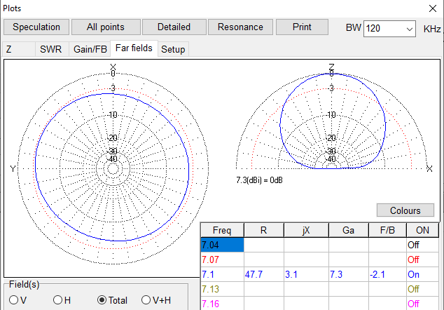
Here are the results of my simple MMANA simulation.
Measuring the antenna on an analyser will always need a link from the feed-point via coax as the analyser has a coax socket. (However that short length of coax should not be close to a quarter or half wavelength long otherwise that will affect the readings dramatically).
My RigExpert indicates both the SWR and the impedance and resistive, inductive and capacitive loads that it sees and these change when for example the length of the loop is changed. Whether the coax run is affecting the readings, I don’t think so. I have never however seen in any article that the impedance of a horizontal loop is as low as 50 ohms - I have seen values of 100-250 ohms given. In my case mine measured at (approximately) 150 ohms. Earlier constructions had it down at 100 ohms when it ran in a different layout in the garden. So perhaps, as your model shows, having it a perfect circle at 7m AGL will bring the impedance down to 50 ohms?
I wish I had the room to install the antenna in a perfect circle as that would also give the maximum area within the loop, which equates to maximum gain (or so I have read).
I believe your model is based on a perfect circle of wire? My actual installation is nearer to a triangle shape - just because that’s the only way I can get it in my small garden.
If you are getting 1.08:1 from the antenna without any transforming balun or Q-section that would confirm that you must be close to 50 ohms.
As always there is what should be in theory and then different results in practice - your model also indicates the antenna should be good for NVIS which is not my experience, perhap[s because of how I have the loop run.
I see very little gain on 40m over a dipole but on 20m I would confirm it to be about 1.5 to 2 S-points better than a dipole but almost more important, on all bands my noise level is 1 S-point less than when using a simple dipole.
Everyone I have talked to who has been able to put up a horizontal loop - no matter how constrained in shape - has said they have been surprised by the improved performance over other wire antennas.