It’s a bit wimpy to be honest as the max anode voltage is 600V.
![]()
It’s a bit wimpy to be honest as the max anode voltage is 600V.
![]()
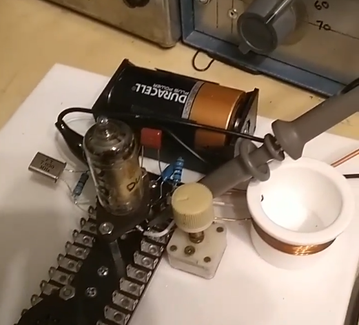
Yes. Here are 2 clips - sry in german - about my first attempt to use axial inductors. I myself was very surprised to see that it works so well.
73 Chris


That’s absolutely brilliant Chris many thanks for posting 
73 Paul G4MD
Thank you Paul
I’m always surprised myself that two of these filters are enough to select clearly over the AM bands.
I also find it fascinating how well you can judge the AM modulation with a tube superhet. The quality of the audio depends largely on the AGC. Here I was able to improve something compared to this example.
73 Chris

Just like this ![]()
73 Chris

Master oscillator Power amp valve rig from the 1940s? They don’t make them like that these days.
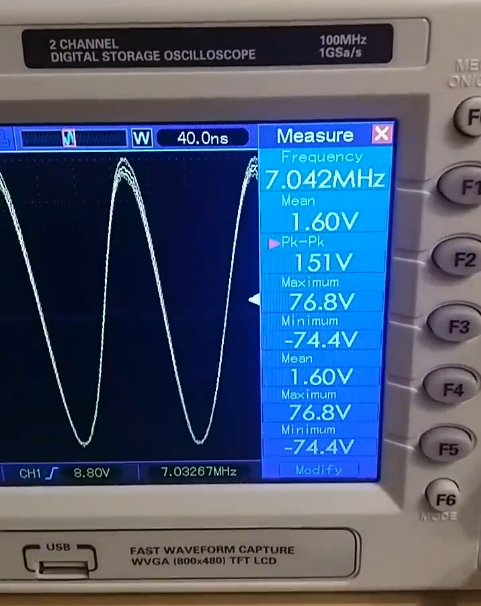
Me again  I’ve been playing with a DL96 in this circuit. I can get it to oscillate in the 40m band (7.030) no problem. But in the original article it says if you want to operate on 20m just double. So I would assume they meant to tune the anode of the osc (not the PA) to the second harmonic. It seems the gain of the valve is just not up to this on 20m. Even with an injected 14MHz signal to the grid and the anode tuned for resonance, the level of signal seen at the anode is well down
  I wonder if you have tried to run this circuit on 20m ? Also, using a 7.030MHz crystal and tuning the anode of the osc to the same frequency you come against the tuned grid / tuned anode issue and you have to off tune the anode to get the circuit to oscillate The solution to tis second problem would be to have three stages Osc/Buf/PA. but that’s another valve…
Hi, no, I haven’t tried tuning the anode to second harmonic - but I might, now that you mention it.
The osc anode tuning is as you describe at fundamental, though.
Interesting. I’ve played a bit now with this style of MOPA CW Valve TX and keep coming across this tuned grid/anode issue I did try with a 3.520MHz Xtal hoping to be able to tune the anode to 7.040. But even that did not seem to give any output. I’ve put it to one side now and dug out an ECL82 (triode/pentode) with a 6.3V fil. Toying with the idea of using one ECL82 as a MOPA TX and a second as a Regen RX, on 40m. series connection of the heaters for 12v and an inverter running form the 12V for 250V HT. I’ll try and get the TX going first
Thinking on my feet so bound to be wrong. But for doubling you need enough harmonics to amplify, that suggests you need to bias things so there are harmonics. In the BJT frequency doublers I’ve seen you run them in Class C. It could be your biasing is too linear.
I could be wrong so correct me if I am.
I agree totally. You could run another buffer / amplifier stage between the OSC and PA in class C to give you more harmonic output. There are also oscillator designs which are higher in harmonic content. However… Even removing the crystal and driving the grid (of the OSC) with an external Sig Gen, the gain of the Valve falls off quite rapidly with increased frequency (re-tuned the anode as I went  ). So I doubt there would be much there (on 20m) even if the valve was driven hard. I’m pretty sure these Battery valves were designed for Audio & LW/MW, and so its quite possible that this was not an issue in the intended circuits. All part of the learning experience…
I’m not sure you’re actually amplifying harmonics in a frequency multiplier, I’ve always visualised it as the multiple frequency being generated in the anode tank circuit - imagine a child on a playground swing that’s only given a push every second or third oscillation… But it comes to the same as far as the valve (or other active device) biasing is concerned, it needs to be biased to give a small conduction angle (ie class C) so it gives the tank circuit a good hard push.
TBH I’m not surprised that the DL92 and it’s ilk don’t perform well at higher frequencies - they were never envisaged as anything other than audio amplifiers. Ones intended for RF/IF service (DF92 etc.) may perform a bit better, but even these weren’t expected to do much more than Medium Wave.
I’m playing with a transmitter based on a pair of EL91’s, they were specified for RF as well as AF service and in series the heaters will run perfectly from a 4S LiFePO4 battery. Hopefully will give me a couple of watts out too ![]()
73 Paul G4MD
My late chum Denis G3UVR had a topband TX using an ECL80 as a youngster. His father’s radiogram had an ECL83 or ECL85 in it. That gave more Watts. He used to borrow the radiogram’s output bottle when his dad went to bed. It all went smoothly till it failed in RF DX service. There were some strong words in the following days ![]()
Paul,
Yes if using a tube frequency multiplier you need to run it in class C. Harmonics in the input are not required and may be more trouble than they are worth.
73
Ron
VK3AFW
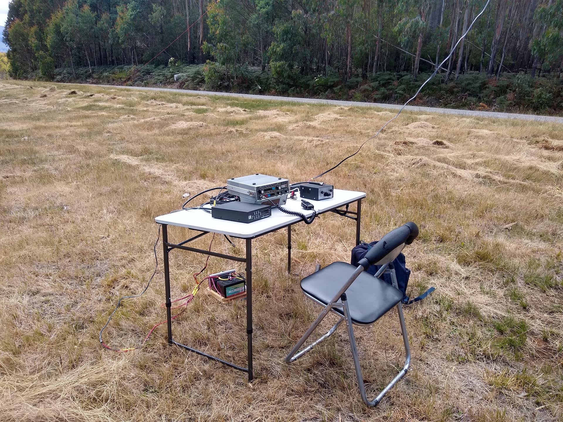
Inspired by this topic I took my FT75 on a successful activation yesterday. 18 W out on 40 m instead of 25W due to 50 yo tubes.
It’s a hybrid so maybe cheating as it has a discrete transistor receiver and exciter.
The station on Mt Stricktland. VK3/VN-030.
73
Ron
VK3AFW
Ron,
You’ve given me an idea. I do have some tubes in the shed, I could take a tube out to my next summit. would that qualify as a tube on a summit? It’s a YL1060 in a 2m ssb tx built by Ed 1VP. I can’t suggest taking the entire transmitter, it weighs 20 kg+. There may be a 3/12 in there too.
I like the pic of your setup. I bet the designers at Yaesu never dreamed of anyone doing that in 1970.
73 Andrew
Hey Andrew,
I have a sneaking feeling you are supposed to use at least one tube on the summit for transmission and/or reception rather than as a talisman.
I’ve likely worked that transmitter. Its just the 20 kg, it’s the alternator needed to power it. I think Ed used it on Mt Ginini, so get to it. Ed must have had help and wasn’t going to go unless my presence at the other end was guaranteed.
Yes Yaesu designed the FT75 rig as a mobile, not a portable. But some FT101 series I seem to recall came with a carry handle. Very good for stretching the arm.
73
Ron
VK3AFW
Oh, you’ve seen through my ruse.
I think in the 70s and 80s that transmitter was the one Ed used on 144 both at home and in the field. The YL1060 (iirc) was a tube that was capable of 80w output on 2m ssb. Intermittent! It looks like a grown-up 6/40. So yes you would have had contacts with that tx.
73 Andrew VK1DA/VK2UH
Hi Andrew,
You under rate the YL1060. It is capable of 400 W SSB out on hf. See Acitrton transceiver, sold by ACI electronics.
I got over 200 W SSB out on 2 m with my QQE06/40 transceiver. I used to run 80 W of carrier out in AM service. With a pair of 807s modulating it. That’s over 300 W peak. I still have the 6/40 and the transvertor. Sigh.
No wonder my garage is overflowing.
73
Ron
VK3AFW.
Yes I think the Acitron was what gave him the idea of using it on 2m. In that tx the limiting factor would have possibly been the inbuilt power supply. I saw the Acitron demonstrated.
73