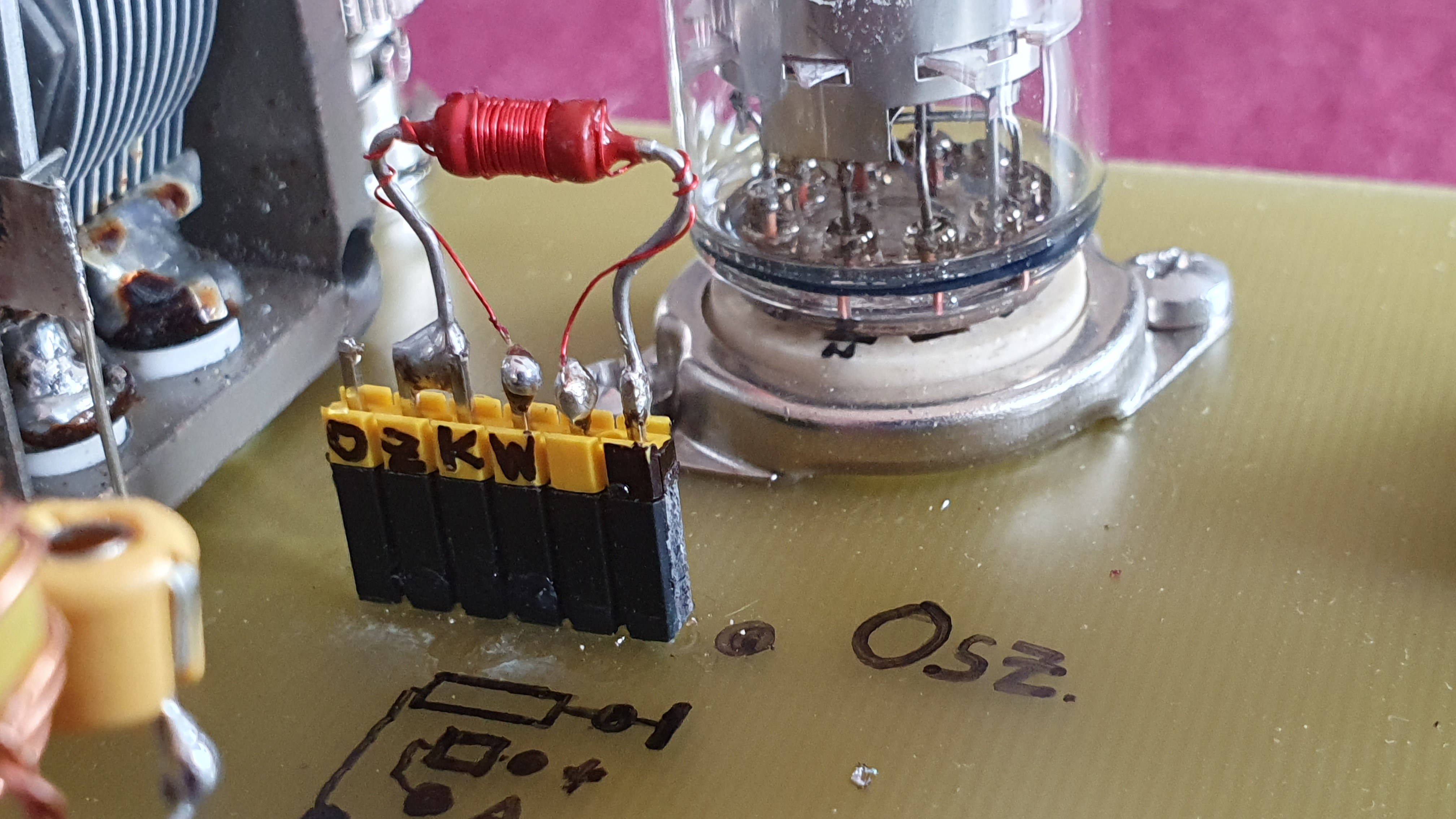
Most definitely! Back in the day standard values for RF chokes were 1mH or 2.5mH. Nice pie-wound RF chokes are like rocking horse droppings these days so a 1mH moulded axial choke should do fine in this circuit
Yes indeed - 1W input is pushing the ratings of any of the DL9x group to the limits. They are very fragile, especially the filaments :-s
I’ve been running this for about 3 years on 80m (including for the GQRP Valve weekends). 5w output with 250VHT and no Chirp. So using small crystals with valve circuits can be done
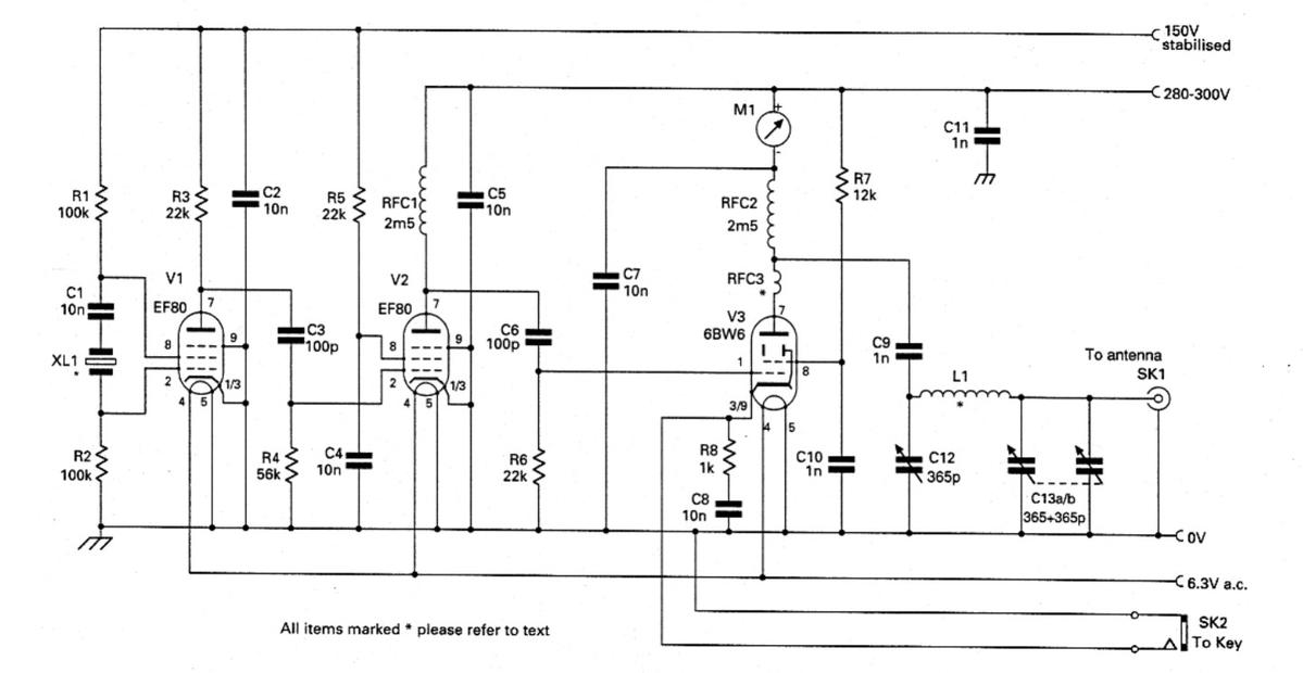
Combination of an electron coupled oscillator and a buffer stage. The biggest issue I had was getting enough drive for the PA grid. I found the solution was a parallel resonant circuit to ground (at 3.56MHz) in the PA grid circuit (between 2 100pF caps). This replaces the single 100pF cap between the Pen and PA stages. Now I can get well in excess of what I need to drive it, and actually have to take it slightly off resonance to back down the drive
Neat! Classically elegant circuitry - essentially the RF section of the Codar AT5 but with a Pierce crystal oscillator instead of the Vackar VFO
The Pierce circuit can be a bit hard on crystals if pushed hard, something like a Colpitts where the drive to the crystal can be tamed by tapping down the capacitive divider might be worth trying (though using directly heated valves requires use of a bifilar choke in the filament supply to allow the filament to operate above RF ground)
Very interesting and instructive details. Thanks for hints. In particular, I have never seen the feedback from the quartz oscillator via the screen grid.
I am considering a tube tx with vfo. For the anode voltage I will use an inverter like this.
I’ve used these inverters. They are great as the also have a negative output. I’ve even used one with an old PL504 line output valve and got 10w carrier out in class C, using the negative side for grid bias via a pot Lots of fun.
You could reduce C1 to maybe 33 pF to reduce the crystal drive if it is excessive. To control the PA drive you could fit a 50 k 3 W pot to G2 of V2. Grid to wiper, ends of pot to ground and B+.
I actually meant his brother the 5B/255M where there’s no top cap anode. You can keep all the voltages that make you dance under the chassis with that one.
100% agree Ron.
Just the way the circuit developed. There are always multiple ways of achieving the same goal. That said, this does gives me the ability to tweek / set the optimum drive level (I have multiple Xtals). My Heathkit HW-40U does similar.
A fellow ham recommended the addition of a resonant circuit like this. I’ve tried it with a MOPA Osc/PA setup, but then you have the “tuned grid / tuned anode” issue and you can actually stop the oscillator (or at least make it tempremental) by setting the anode to the same frequency as the grid on the osc. One solution to this is to tune the anode to a multiple of the grid frequency (I plan to do this in a future 20m band TX using a 7.030MHz crystal with the anode of the osc tuned to 14.060MHz). Or, as in this case, using a buffer to isolate the Osc from the PA.
I’ve learned a hell of a lot with this simple circuit and this was the original intention of building it Glad of any advice / knowledge sharing…
73
Rich
G0GGA

 Cheers