I first saw a dynamotor in 1973 when I was just out of short trousers. We had a radio club at my school and the teacher who ran it was into US WWII surplus. He had many dynamotors in basement rooms at the school. I often what happened to them after he retired and had to clean out his collection. Or when he died a few years back. I used to visit him when I went “home” to see my mother and his house was creaking under the amount of green radio gear.
They sell for stupid money now if you have a working one in nice condition. Still go for a good price if tatty.
The teacher was a real character… he’d worked at Windscale Works as a lab tech back in the fifties and had actually seen Plutonium metal produced for the UK Nuclear weapons. Not that many people can claim that.
Yes, sir! That photo looks familiar! I found a photo similar to my first
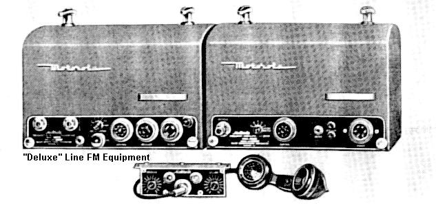
dynamotor powered 2 meter rig. Mine was a “LINK” but the Motorola
in the photo looks very similar. You wouldn’t want to be hauling this baby up the hill on your back to work 2 meter FM! This was a MOBILE unit of the late 1940’s-3arly 1950’s.
This thread brings back memories; Started career in summer, between elementary and junior high school as an apprentice in a radio shop. The police were changing over from AM, just above the broadcast band, “calling all cars” to the new Motorola VHF FM. So spent a lot of time drilling holes in cars and brand-new Harley Davison cycles! As a newly minted ham in 1955, carried a BC-611E handy-talky to call CQ on 75M (3.885 Megacycles) in distant towns, to ask about where to eat, stay, etc. Later, had Morrow twins with a dynamotor HV supply for transmitter, vibrator supply for the receiver; This in a '57 Chevy.
Best, Ken K6HPX
Very swell, Ken! Yeah, those were the days. We got those LINK rigs
from the Sacramento Co. Sheriffs when they upgraded in around 1964.
I took out the dynamotor and built an AC supply inside the transmitter.
It was my only 2 meter FM rig for years. We had one simplex frequency in Humboldt county and that was it. No repeaters, etc.
In mobile service, a 6-volt model drew 82 amps on transmit! What a
beastie! (keep the engine running!)
73, John
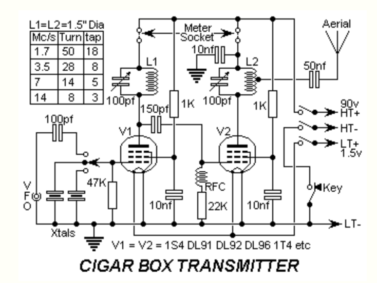
Hi Adrian, it looks like I may be building the same circuit as you. Was this the “Cigar Box Amateur Transmitter” from March 1955 Practical Wireless ? I’d be interested in your experience. I’m looking to build a similar level RX and put them both into one box, running on 20m.
73
Rich (G0GGA)
Yes, that’s the circuit that I built - I used torroid cores for L1 and L2, and a link coupling for the output as I didn’t intend to use it with a half wave wire antenna.
I haven’t attempted a receiver to go with it yet, and the nearest thing to a QSO has been sending “CQ” and seeing it pop up on the RBN.
It has a distinctive “chirp” when keyed, which I suspect is the battery voltage sagging at key down, but I haven’t investigated yet - I have heard worse!
Good luck with the build, and please let us know of progress…
Yes Adrian, you have to be careful if you use a modern crystal and valved oscillator that you don’t have too much current in the crystal or it cooks them and bad things happen. I need to acquire a suitable FT243 as I have an ECL85 (new in a box) destined for simple TX. One of my many retirement projects. Or when I retire I may to get finish things started a long time ago.
Hi again Adrian,
Glad to know you got it working (spotted your other post on this, after I sent you the message, and felt a little silly for not looking .
Hope you don’t mind me asking you a couple of questions about it…
Firstly, what size choke did you use for for the PA grid ? The article call for 3H, which seems really big.
Secondly, did you manage to get 1W out of it ?
I have some little Chinese inverters I’ve been using for various single / dual valve CW TX projects and I thought I’d try one of those as a PSU.
There was an RX to go with this TX, in the May 1955 edition of Wireless World, but as I want to use it on 20m I think a regen would be pushing it, up at such a high frequency. So I may try a tunable regen on 80m and then a fixed down converter from 20m. Hopefully this will be more stable.
When I was in my teens (in the 80’s) I read a lot about valves, but have not until recently started to work with them. Learning a lot and making a nuisance of my self with the older members of my local club, who struggle to see why I should want all the hassle
Regards
Rich (G0GGA)
I reckon the reason for the chirp is a bit more fundamental than the physical size of the crystal. Also needs some work on the output circuit, even at QRP levels the given detail would be extremely antisocial (not to mention of dubious efficiency)
But a very interesting thought stimulator… I’m inspired to start rooting through my valve hoard and get designing
Take a look at Hans Summers Website. He gets away with a modern Xtal (as have I in a few valve TX projects). It depends on the circuit. Running a power osc with an 807 would be an issue. But some lower power oscillators should be OK.
If i remember correctly the crystal frequency can be affected by the impedance across it, which in turn changes if the load on the oscillator stage varies. So as the final amp is keyed, the frequency alters in step. This is where buffer amplifiers come into play. Without them it is very difficult to avoid chirp. Dual Tubes like 12at7 dual triode (if they were avail in 1v filament types) or even a triode/pentode tube can give you a buffer amp separate from the oscillator stage. Reducing the coupling from the tube elements to the crystal may also help. As would reducing the screen current with a higher value of screen resistor in the oscillator stage.
Keying the dc supply to the entire transmitter would also be a source of chirp. Running the crystal oscillator continuously should reduce it. But otoh a chirp is sometimes a nice feature of a simple tx.
As I recall, there is no buffer in the Hallicrafter SR-75, which is an S-38B with minimal added components to produce a ten watt transceiver. All three of mine chirp like crazy, requiring me to reduce power well below ten watts. I even got a pink slip from the authorities for chirp.
Quite correct! In this circuit (a simple tuned anode - tuned grid oscillator) you are relying on the capacities between the valve electrodes to provide the feedback path, these will vary with applied voltage, heating within the valve etc. so you’re on a bit of a loser to start with.
Usually you wouldn’t tune the anode circuit of a TATG crystal oscillator to the fundamental crystal frequency anyway due to pulling of the crystal frequency as the anode circuit is tuned, indeed tuning can be very fussy to get it to oscillate at all. Behaves much better if you double the frequency in the anode circuit.
Or better still use another oscillator topology that shunts and swamps the valve capacities with stable external capacitors
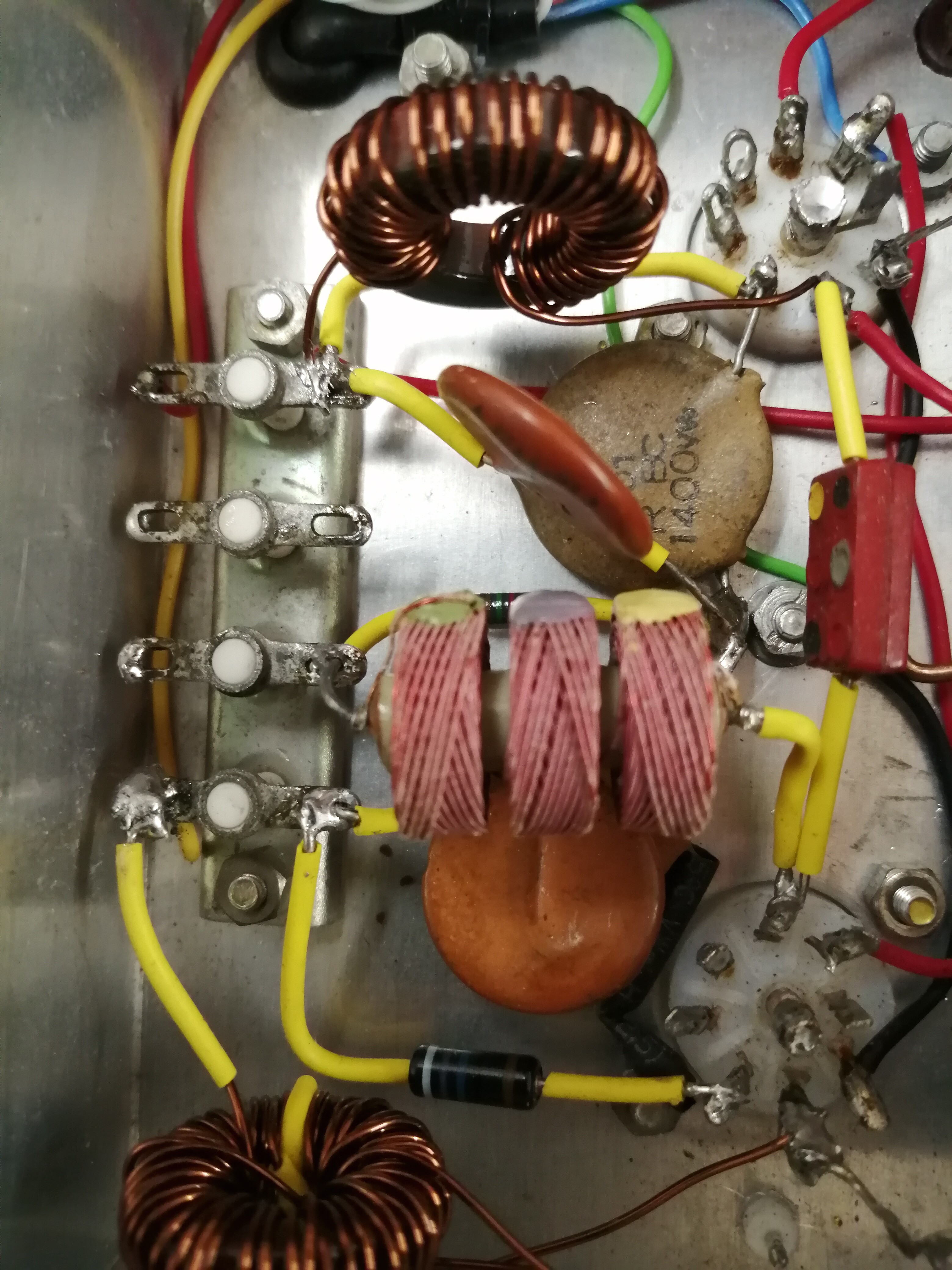
Yes, I’m sure 3H is a misprint! I just used a valve era RF choke from the junk box (see photo below) which seems adequate as there is enough drive to push the output stage into class C.
No. I get about 400mW, though I round that up and describe it as half a watt :o).
I doubt whether the author was able to accurately measure the power output delivered from a high impedance tap on the tank coil. In 1955, it is more likely that dc input was quoted, and that’s about what I’m seeing - actually a little more than 1W in, IIRC. I haven’t been able to improve the efficiency (I have tried the original type of solenoid coils, and checked waveforms, grid current etc and made various other changes, but with little effect on the output).
Yes! I pondered that, but then I was building it for nostalgic interest, and to justify keeping a “junk box” going back over 50 years. I have put it on the air for a minute or two to be picked up by RBN, but I won’t be clogging up the bands with it.
Yes, in a world where signals are almost always T9, a little chirp gives it character. I have heard and worked far worse.

 .
.