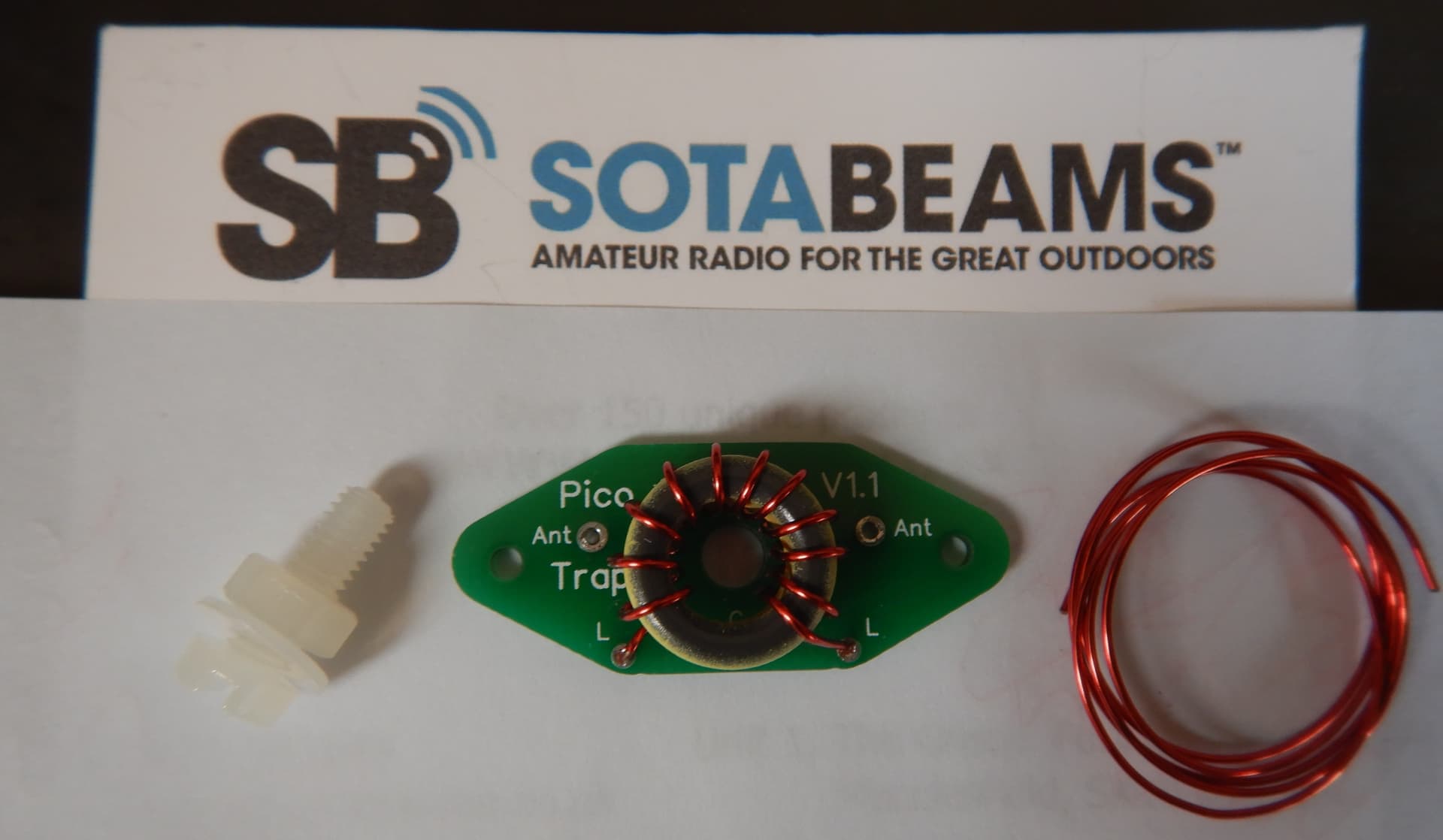
Hi, I’m planing to build a trapped EFHW antena for 20,17,15,12m bands. I have just ordered the sotabeams pico trap. Anybody has done this before? Does the antenna work well? Are 3 traps ok, or better to go only for 2 traps (20, 17,15 and 10)? What are your experiences? Tnx. 73
PS: Me idea is to use the antenna with the QMX Hi-Band.
I was the first person to try to make tiny traps in 2011. I could find no evidence anyone had tried before. From experience: These traps do not work well. There is a reason that commercial traps are big and primarily inductance. You need to keep careful monitoring of the traps resonance. It isn’t enough to set it and forget it. As you go along, securing it, it can change. You can use silicone caulk to secure, but you can not use hot glue, for example, it will change its frequency. The selected resonance frequency needs to be close but below the operational frequency.
In general, these toroid traps seem to work better with more inductance and less capacitance. However, you may find that with a lot of inductance in the 17m trap, resonaNCE FOR 20m HAPPENS inside the trap, and won’t resonate for 20M. Also, you may find the antenna resonates on 12M without a trap and a third trap may make things difficult to impossible. Each trap has inductance, how much depends upon the capacitor to turns ratio you select. The more inductance, the more shortening of the wires beyond it.
You may be better off using the smallest SPST switches to achieve multi-band resonances at these frequencies rather than toroid based traps.
I also came to a similar conclusion.
My trapped 20/30/40m half-wave antennas still work well after many years, but the EZNEC simulations of a trapped 10/12/15/17/20 m half-wave antenna showed me exactly the unwanted mutual influence mentioned.
So my easy-to-use, lightweight 20-10 m portable antenna will consist of a Z-Match ATU (see link below) and an approx. 9.5 m long antenna wire. Because this antenna length is medium to high impedance on the bands mentioned, the Z-Match ATU results in efficient adjustment and 2 radials of approx. 2.5 m are sufficient.
It would also be worth mentioning that with this antenna length on the 17-10 m bands, flatter radiation angles and slightly more antenna gain result than with corresponding half-wave antennas.
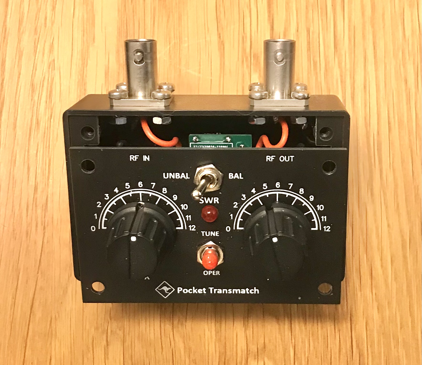
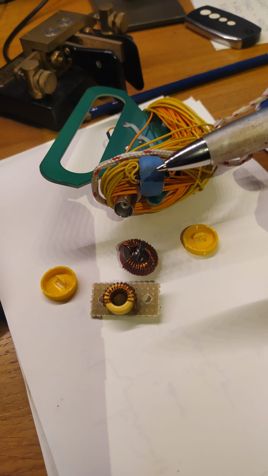
BTW, The final assembly of the Kanga QRP Ttansmatch with the case is actually a bit of a watchmaker’s job, hi.
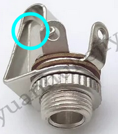
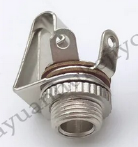
In order to gain a little more work space, I replaced the original BNC sockets.
When you put a trap in, you move the harmonics so your 20,10 EHFW will no longer do 10 after you put a trap in.
The usual drawback of linked antennas, is how far away the links are. For ~10m of wire in a V, they will only be 4 metres away, so not much of a walk.
For a short antenna like this you could also put the links at the operator/feed end. This is even easier to get to.
If you use plugs with an insertion switch i.e. barrel (power) or 3.5mm headphone, then you can put a switched jack at each band point. When you plug the feed in, it cuts the wire and feeds it. Very easy.
For 20,10,15,17 your feeds will be only be +/-1.5m from the operator position
12m is a bit awkward as the lengths are quite different
This also looks like it would work OK to make a 40m EFHW do 17 and 12m
You might note that it would be easy to make it a simple 6m dipole fed at the 17m point. That solves the issue that the efhw ferrite transformer is pretty poor at 6m.
Yes, about 5 years ago I made a trap type EFHW antenna with “Pico Trap”.
However, it was for 18/15m (only one trap).
It worked very well than I expected.
The Pico Trap itself is not sturdy, so you should make sure the Pico Trap is strong enough to withstand the tension. GL.
As an alternative to SOTABeams PICO traps (which I have and they are fine), I can recommend the ones from HF-Kits in Holland (hence easier to get than ordering from the UK for EU residents). These are currently shown as out of stock but will soon be back in stock, I expect.
Frank has a revised design which is even simpler to build for the band of choice. Antenna trap kit, ideal for wire antennas - HF kits
You can change length at either end - only the total length matters, except that if you do it at the feed end, you have to break the wire and move the feed connection
(connectors are ><) ...string....-------------10m total wire-----------------....string.... ....><------1.7m------><----1.2m------><--------8.1m---------.... 20m jack ........17m jack ........15m jack ...
lengths are approximate
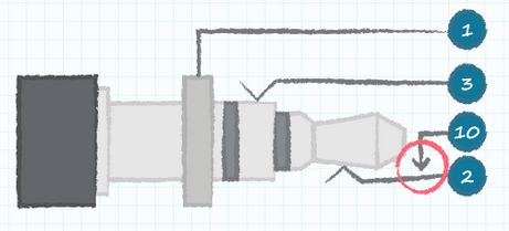
The sockets have a normally closed contact in them. i.e without a plug, the two metal strips are joined, when the plug is in the tip contact is pushed away from the strip.
When you plug the feed in it breaks the wire, and connects the hot end of the matching transformer to the long wire (2), and (optionally) the cold end to short tail as extra counterpoise. So in the example of a stereo jack here:
‘1,10><2------1.7m------1,10><2-------1.2m------1,10><2-------------8.1m-----------’
You connect the 49:1 transformer to a 3.5mm plug: Hot - tip(2), cold -ring(1)
Note it will work without the cold side / counterpoise connection as you don’t usually have any extra counterpoise anyway and just use the coax shield
There are two common families of connector with switches: Jack plugs (3.5mm and 1/4") and barrel (DC power) plugs (which have the switch in the outer sleeve)
You can use mono or stereo jacks
Note you could also do this with two small toggle switches (at 17, and 15m points) and a crocodile clip on your transformer to connect to the antenna wire.
What to do about 12m?
a) have a 12m socket at 4m.
b) (untested) modelling suggests that plugging ~2.2uH into the 15m socket (while feeding at 20m socket) will make it resonant on 12m (only)
Nine years ago I also played with a 5 band EFHW vertical with 4 traps for 20-10 m. I compared the antenna directly with the second antenna in the field. To my 4.8 m long vertical antenna with 1:4 UNUN and 3 radials with 3.5 m length. The trap antenna was 2-4 dB lower depending on the band.
Perhaps this was due to the UNUN (FT140-43 with 2 + 14 turns). I had optimized the Sotabeam traps with MICA capacitors. Perhaps it would have been better to tune the traps slightly below the operating frequency, which can lead to less loss.
If the TRX does not have an antenna tuner, such a trap antenna makes sense. Otherwise a vertical with 1:4 UNUN is the better choice for me.
To avoid “soil changes”, I made my linked dipole with 2 meters of nylon, stuck to the ground. I’ve never had any problems with the SWR changing. As for EFHW, the one at 10, 15, 20 and 40mts, with 20.75mts of irradiant is Excelent, but does not work at 12 and 17, high SWR.
I injured my finger, but in February we restarted SOTA activations in PY2.
I hope to hear them.
73 everyone and happy new year.
Carlos
PY2VM
Hello
I made sotabeam traps, there is little isolation between bands, it is difficult to tune the antenna’s SWR. I made the traps designed by Fred KT5X, with these PCBs OSH Park ~, they are better, but…
My EFHW has traps for traps for 20 and 30 meters, (works on 20, 30 and 40 meters)
-20 meters works well
-30 is acceptable
-at 40 meters it is bad because due to the effect of the traps it is very short and has little bandwidth.
The SWR is normally good on all bands (max 1:1.5), sometimes on 40 meters (swr 1:2) I change the antenna configuration to be better.
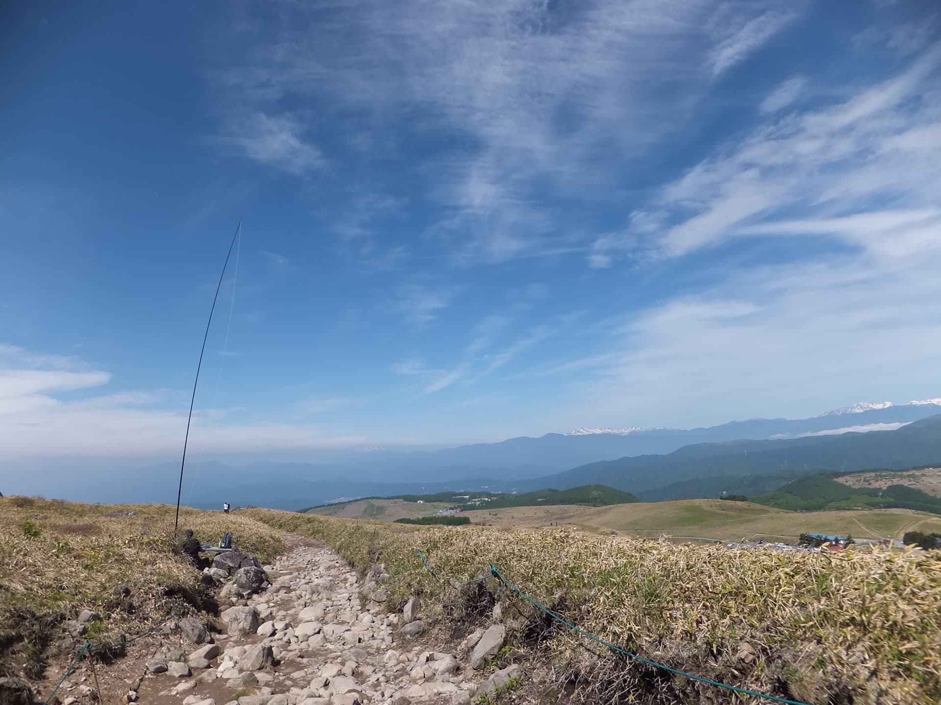
The mast is around 5 meters, I normally mount it in an Inverted L, Inverted V, or slopper, depending on the reference.
One more thing, very close bands make it more difficult to adjust the antenna.
The trap boxes were 3D printed by a friend
GL, 73 CT1HIX Gomes
I am not an RF engineer, but I did manage to finally put together a trapped end fed for 20-30-40. I run it into a 49:1 transformer at the end, with only 6 inch coax to connect it to the radio. I have done quite well with it.
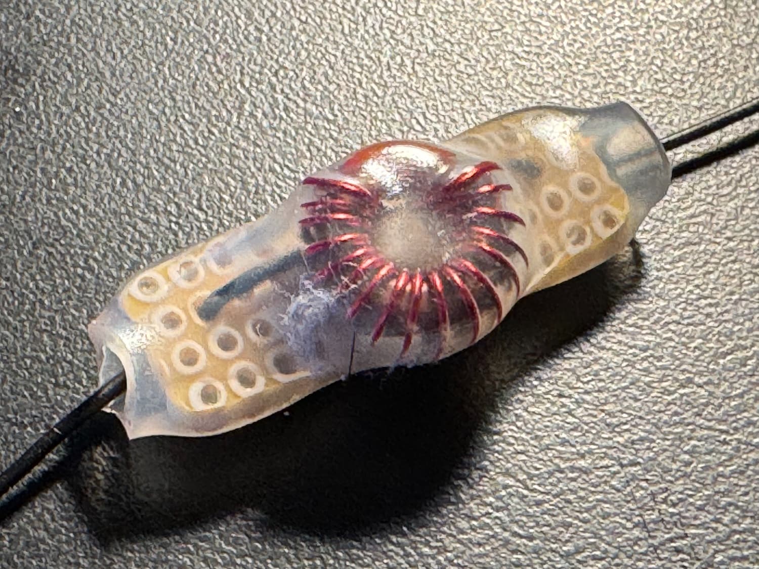
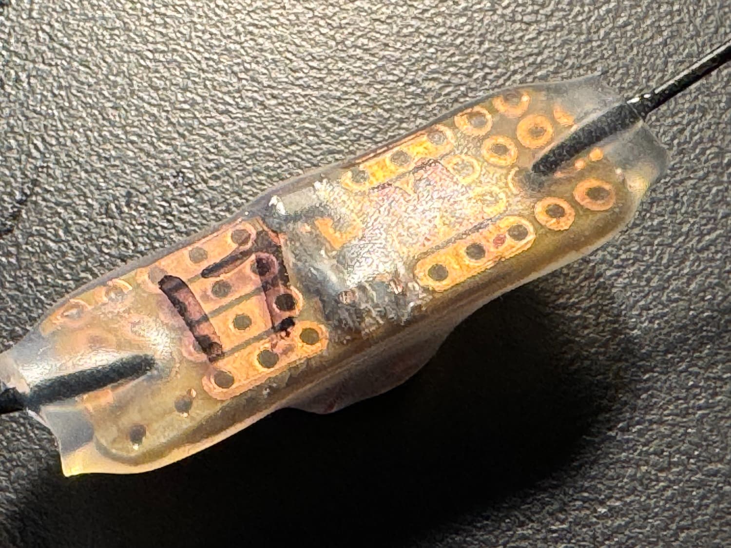
After many attempts to make a trap using the K6ARK method I finally came up with my own solution, which looks like some of the others here. However, one thing I did was to enlarge one of the circuit board holes so I could pass through a short length of 26AWG insulated wire to connect to my antenna analyzer. This made it easy to tweak the winding spacing until I got the desired resonance. To fix it in place I used heat shrink tubing that has adhesive on the inside.
Under most circumstances I end up with an SWR of 1.1 on all the bands. It is, however, a great pain to get the segment lengths correct.
I made a 20/30/40m trapped EFHF antenna using QRP Guys trap kits tuned to 20m & 30m along with their EFHW Mini-tuner (which has a variable capacitor across the secondary). I’ve used it in a lot of different configurations and it works great for QRP. I really appreciate the tuning capacitor as my transceiver lacks an internal tuner. I think the inductance of the 30m trap prevents the antenna from resonating on the octave of 40m without the 20m trap. It was a bit tricky to tune the traps and adjust the segment links. A NanoVNA made it much easier to see what adjustments were required. Its Smith chart display was helpful.
Using two sets of SOTA Beam 20 watt traps (4 total), I built a four band (40, 30, 20, and 17 Meter) EFHW antenna. Used a 49:1 UnUn transformer. Needed 3 traps total. One built for 17M, 20M, and 30M. Tested each trap as specified in the instructions using an antenna analyzer. Antenna Build: The traps change the electrical length of the antenna, so you can’t use the 468/ x MHz calculation to get the wire lengths. Starting with the shortest length, measured and adjusted the wire length going from the UnUn to the 17 M trap, again using an antenna analyzer to get the length correct for low SWR. Repeated the process adding wire and the 20 M trap, then the 30 M trap. Add wire to the 30 M trap to get the antenna resonant on 40 Meters. Was able to get each band’s SWR close to 1:1. Adding each section trap and wire did not affect the SWR of the previous section, as expected. Used liquid tape from a local hardware store to cover and protect the traps. The antenna performs well with my four band Penntek TR-35 QRP transceive with no tuner required. Regularly work Europe (sometimes Japan) with QRP output power. Good luck.