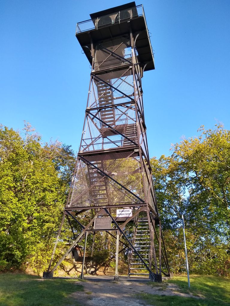
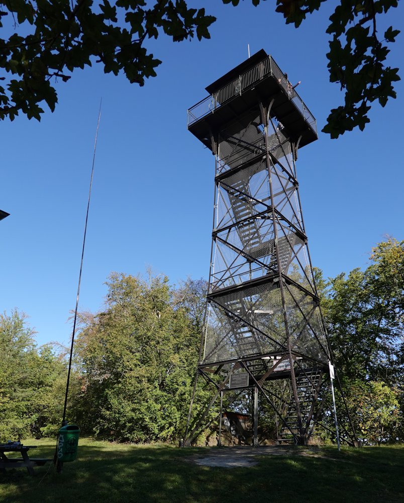
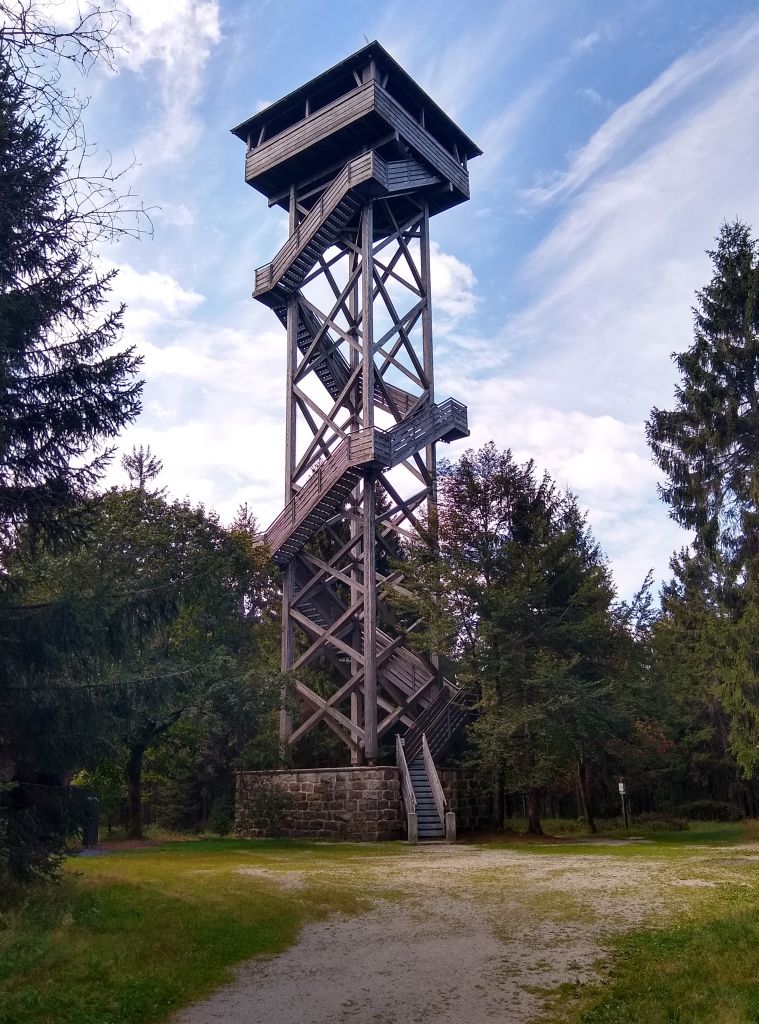
Some years ago, activating Summit Platte (DM/BM-174) my first time, I’ve found there a large and flat summit with a huge lookout surrounded by large trees.
My first thought was to use the platform for operation. An antenna only some meters over the ground would be surrounded by much material with more or less attenuation. But I had no idea how to install one of my short wave antennas on the tower. Hanging a wire down from the top seems to be no good idea. The stairway contains much iron and the tower has also some (lightning conductors).
I saw also no way to mount the pole on the platform. The roof is larger and contains also metal. Therefor my dipole 6 meter over the ground (inverted V) was my choice. After switching the TRX on I was afraid that my equipment was broken. Only a few signals on 20 m and 40 m. With some some luck I managed 2 contacts on 40 m within 40 minutes. To save battery I made a break for 30 minutes and made then 11 QSO within 1 hour, one of my difficult activations.
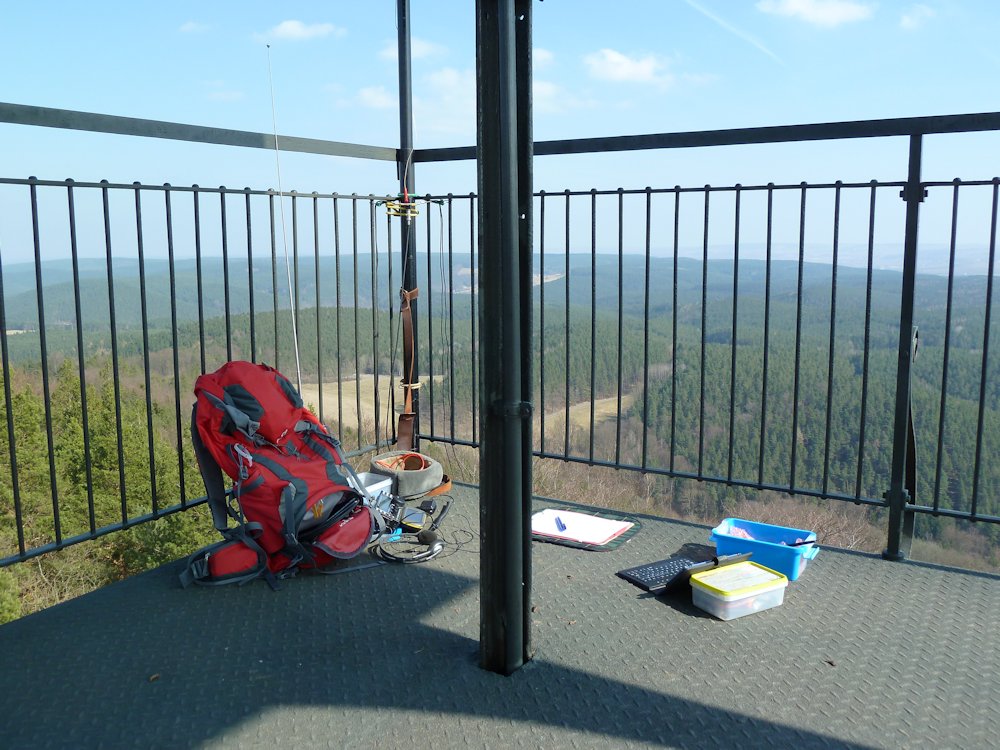
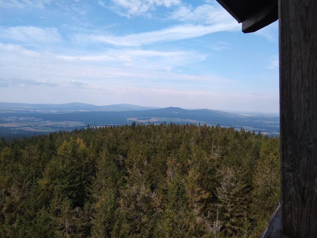
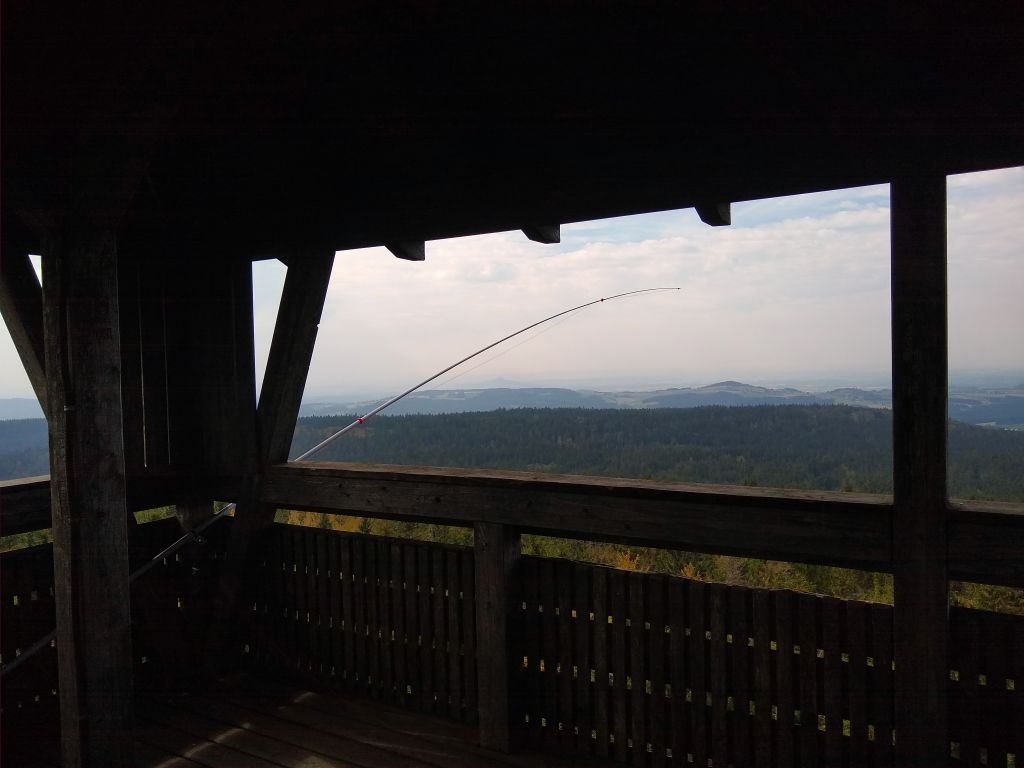
Some weeks ago in 2020, activating Platte my second time, my plan was to work from the platform. From there are no radiation barriers over a long distance around.
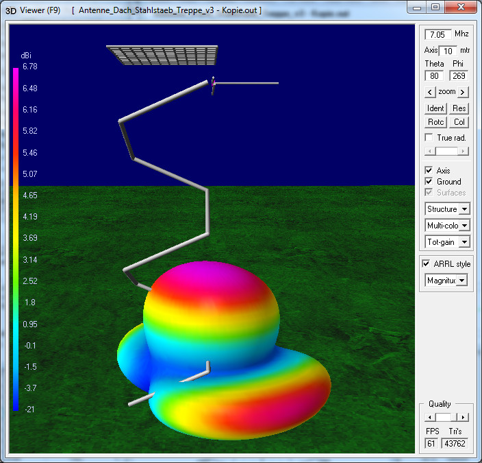
The pole was directed to west. The radiation should go to north, to south, up in the sky and down in the ground . It was successful, 7 contacts on 20 m in 7 minutes (SV, EA, OH, SM). Sorry for chasers in the east and the west. It would cause to much trouble on the platform to change the installation. Some other visitors were there.
It’s a nice experience. I hope to find some other places for my method.
Honestly I would use the platform/tower just for 2m FM.
And then find a quiet spot nearby for HF in the forest.
HF will not benefit from the tower too much I would judge.
And avoiding any troubles with other visitors is also a factor to consider.
Keep it simple.
When considering non-standard orientations, we have to look at the electrical configuration. We see that the 1/4 wave (normally vertical) element and the 1/4 wave single radial now form a half wave dipole. (They do even when set up as a vertical with single radial). Would we usually put half of a dipole so close to a conductive railing or frame of the tower? Not really, we know that its tuning and radiation pattern as well as efficiency will be greatly affected.
Other configurations that would work well, include using the pole as the central support for the antenna configured as a dipole, albeit inverted V in shape, but being already some good distance off the ground would make a very effective antenna, I suggest. The ends of the dipole could either tie off to the tower or all the way to the distant ground. I wish my wire dipoles were 15m above ground.
The single radial vertical is just a dipole, with the side close to the ground actually too close to the ground. However, RF current flows in it, and therefore it must radiate. A lot of its radiation is absorbed by the ground. If you have two or more radials, they also have current in them, but when considering the total antenna field, the radiation from those radials cancels if they are exactly opposite to each other with the same current flowing, and the net effect is that only the vertical element radiates and contributes to the angle of radiation.
Apologies for the long winded comment: I’m en route home and stopped for a cup of tea… the right setup for browsing the reflector.
As mentioned above, the losses of this antenna are quite high. You would be better off with the vertical at the bottom of the meadow with a little distance to the tower.
But such towers are very suitable as a support for long wire antennas, which you can guy down. A ZS6BKW for example and some strings doesn’t take much space and doesn’t weigh much.
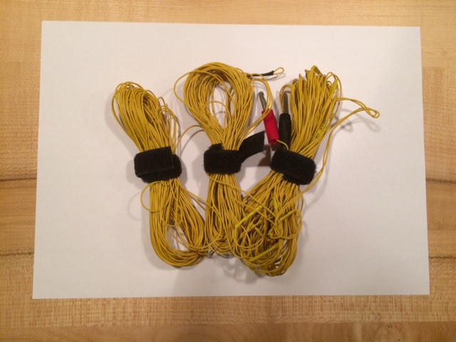
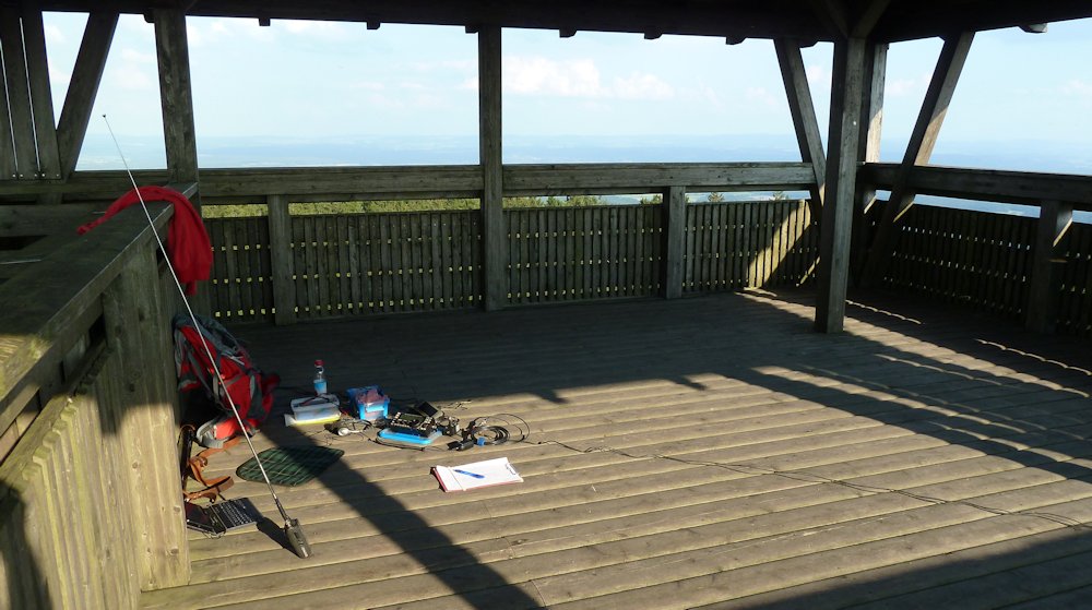
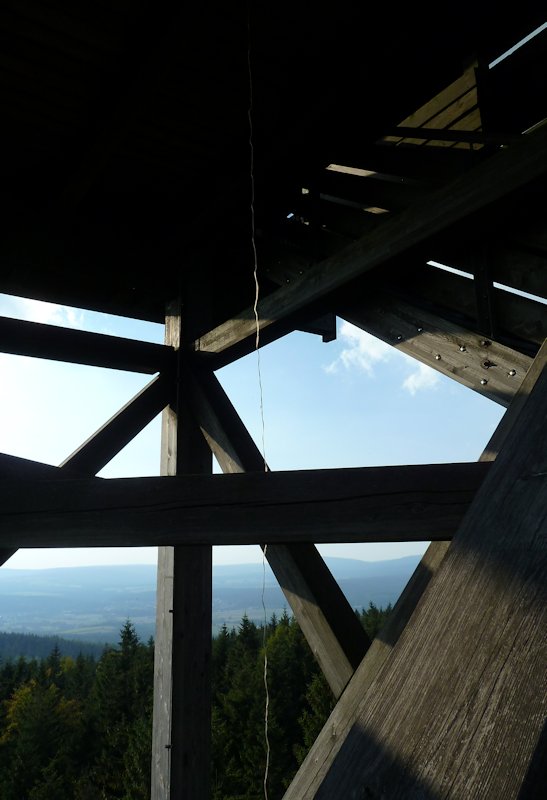
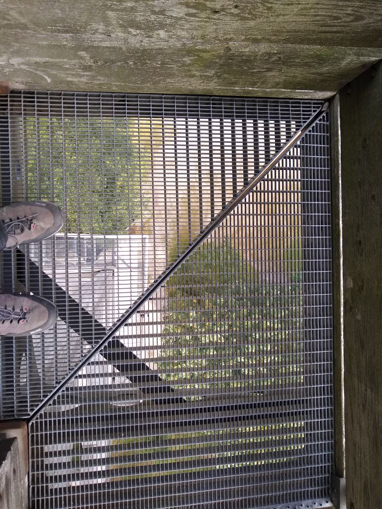
I had done exactly this on 10.09.2016. I had my 10m vertical wire dangling down from the middle of the platform and two radials spread over the floor of the platform. Here are pictures:
I was aware, the metal staircase and the lightning conductors would eat up most of my 10 W from the KX3. But why not try out, what will happen?
40 QSOs in 31 minutes calling CQ and another two calling other activators for S2S. Seems enough HF escaped this trap. As I wanted to activate the near castle ruin Weissenstein, I packed up after 45 QSOs including 2m FM.
I had done exactly this on Platte, also. I affixed my pole at the bench near the hut and the lookout tower on 29.08.2015. Again the 10 m vertical wire with radials for 40 m and EFHW on 20 m. 21 QSOs on 40 m, 4 QSOs on 20 m and 8 QSOs on 2 m FM.
So the summary:
Do not care too much about the attenuation of the trees or even other obstacles. Just set up your antenna in the usual way and see what’s happening.
By the way: The wind generator on top of the lookout tower emits nasty QRM on 2 m. So not a place for 2 m SSB
Honestly I would prefer 2 m FM from such a point, but …
I used 2 m FM during many activations in the past, but with only a very small success, unfortunately. So my main choice is SW, also on summits witch such towers.
@ Andrew
Yes I know my “vertical” is more a dipole, one side vertical and one horizontal near ground. Its a little bit similar to a sloping dipole but with 90…100° in the feeding point. On the tower I used my antenna like a quadrant antenna but with one wire close to the platform and maybe close to much metal. I am not sure about the construction below the wooden surface. Insofar as I remember the settings of my ATU were not so different from those with the antenna mounted on ground. Maybe there are not so large metal parts. I am now curious about the radiation diagram respective to much metal or nearly no metal in the Platform. In the next days I will simulate this.
@ Armin
I was thinking about a wire from the tower down to a point near the ground. During my both activations every time people where around the tower, on the staircase and / or on the platform. I was looking for a simple way to use the tower and interfere with them as little as possible. My solution seems to be usable and I was curious about the results with this version.
@ Michael
Good to know about your experiences.
I do not care too much about this . On many summits I was using my 20 m dipole (with asymmetrical feeding) with good or enough success, also on flat summits and surrounded by many trees or close to a lookout made from iron.
Pole affixed to the hand rail of the tower platform. 10 m vertical wire, the radials are dangling down beside the lookout tower. Log, see SOTA Database - Aktivation 25.3.2018 - to my memory some contest was creating QRM on the bands.
With all the metal mesh around the stairs even I did not dare to have my antenna hanging down inside the tower.
And the variant @DH8WN has chosen: Set up about 10 m beside the tower. In fact in between the lookout tower out of metal and the building containing the large mains transformers for the restaurant and telecommunication tower on the summit.
Log see SOTA Database - Activation 4.10.2020 - I had activated DM/TH-844 before so I was a bit late (mind 2h UCT offset) and did not extend the activation too much in time.
Conclusion: If a few mW of HF emerge your activation site, there is a good chance, eager chasers will pick up your faint signal.
I was using the same place on the ground . The feeding point of my dipole was fixed at the pole 6.5 m over the ground and the power abt. 30 W (FT-817 + PA). Log see here SOTA Database. ODX was NY2PO on 20 m. He received also a good signal only with 5 W on my side.
I was also a little bit late, came from DM/TH-012.
DM/TH-844 was on my list this year, after DM/TH-012 (a nice activation; 21 QSO in 14 minutes on 20 m with short skip SOTA Database)
I was using 4nec2.
The roof over the platform is covered with metal. I guess its something like copper or iron covered by zinc (?). I used a medium conductivity.
I simulated three versions:
v0: normal set-up on ground, to compare
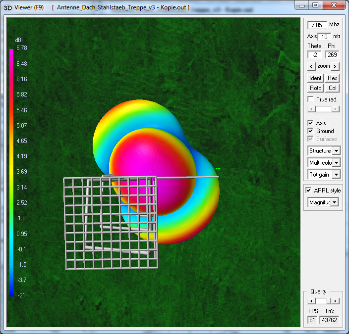
v1: metal on the roof, simulated as a flat mesh of conductors
v2: like v1 but with an additional iron rod under the platform and near the “radial”
Briefly values for efficiency (consider losses only in the antenna) and radiation efficiency (consider losses in the antenna and by the ground):
v0 eff. 92% @ 40 m; 95% @ 20 m
rad.eff. 21% @ 40 m; 28% @ 20 m
v1: eff. 67% @ 40 m; 80% @ 20 m
rad.eff. 66% @ 40 m; 79% @ 20 m
v2: eff. 67% @ 40 m; 80% @ 20 m
rad.eff. 66% @ 40 m; 80% @ 20 m
Using v0 there are only a few losses in the antenna, thin wires but made from copper.
Much loss is caused by the real ground (medium ground).
v1 and v2 are with more but not so much losses in the antenna. The antenna wires and the metal nearby counts as the antenna. Nearby metal parts are with a lower conductivity but with much more surface (skin effect). Nearby metal acts as passive part, stimulated by radiation I think. Ground is far away (30 m). The radiation efficiency is much better then on ground! Losses by nearby metal are much smaller then losses by real ground nearby.
From this point of view the set-up on the tower was fine.
More about radiation directions with my next post.
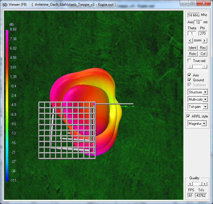
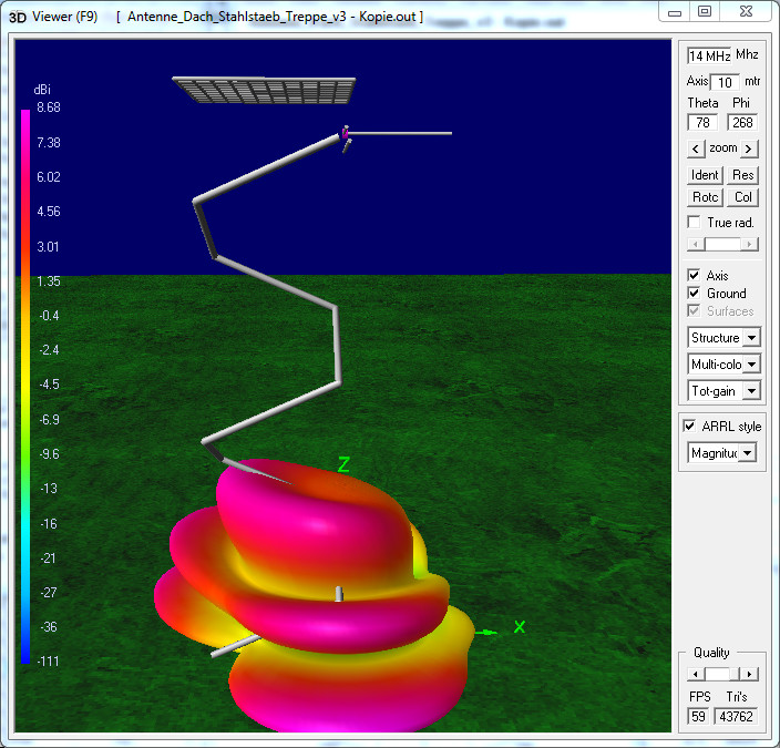
With some more information I made the last (?) simulations.
v4: without stairs but with lightning conductors
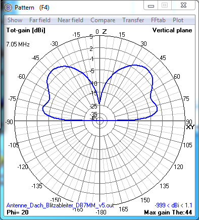
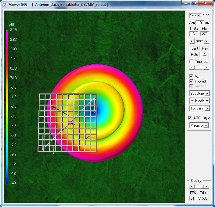
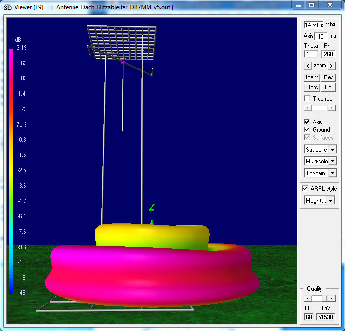
v5: without stairs but with lightning conductors and antenna by DB7MM (inverted groundplane, “wire dangling down”)
v4: Most of the stair is made from wood. The iron steps are not connected to each other. Dimension of steps is small compared to Lambda. So the stairs are not important (for radiation, not for going up and, more important, for going down .) But the lightning conductors may be important for radiation.
Values and radiation patterns further down.
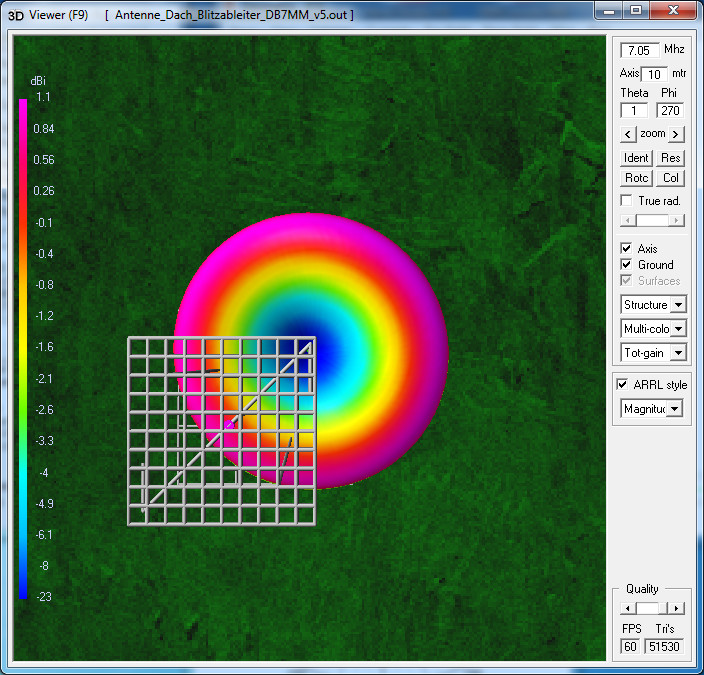
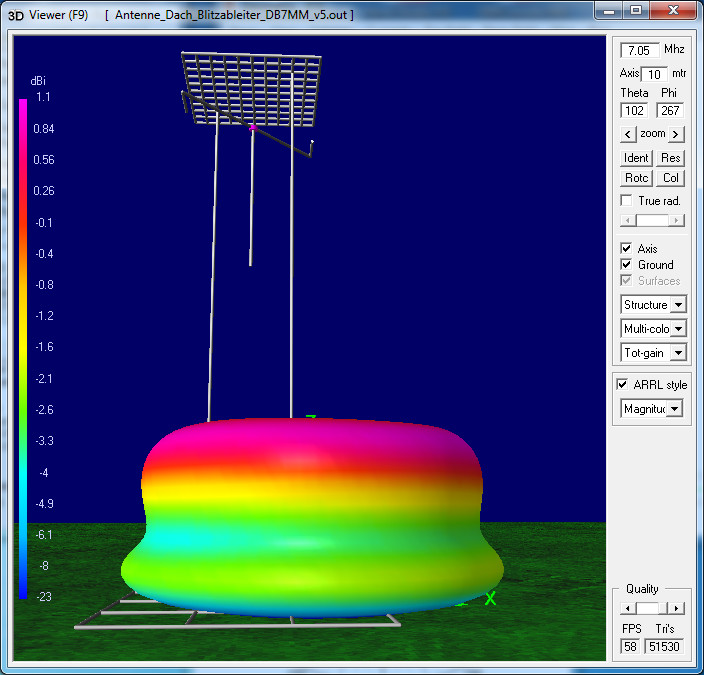
v5: The setup by DB4MM is not common.
Right or not? How is the radiation?
V4: eff. 67% @ 40 m; 80% @ 20 m (same as v3)
rad.eff. 66% @ 40 m; 80% @ 20 m (same as v3)
Patterns for v4 are close to patterns for v3. Small impact by the lightning conductors.
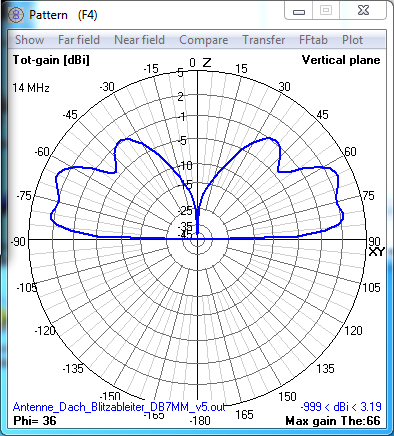
V5: eff. 50% @ 40 m; 83% @ 20 m
rad.eff. 33% @ 40 m; 49% @ 20 m
Radiation efficiency is lower but not so bad (two lightning conductors only 3.2 m away!)
How are the radiation patterns? There are two “ground planes”, on top the radials and the metal plated roof and down the real ground. The radiation may be trapped between.
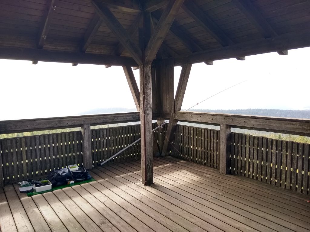
 . It was successful, 7 contacts on 20 m in 7 minutes (SV, EA, OH, SM). Sorry for chasers in the east and the west. It would cause to much trouble on the platform to change the installation. Some other visitors were there.