Hello,
I was working on 3D-printed antenna winders for my EFHW when I set up the antenna in the garden. While analyzing the SWR curve with my NanoVNA, I was intrigued by the SWR reading on 40m, almost 2:1 at its minimum. This was unusual because I had never experienced such behavior while operating in the mountains (rocky summits).
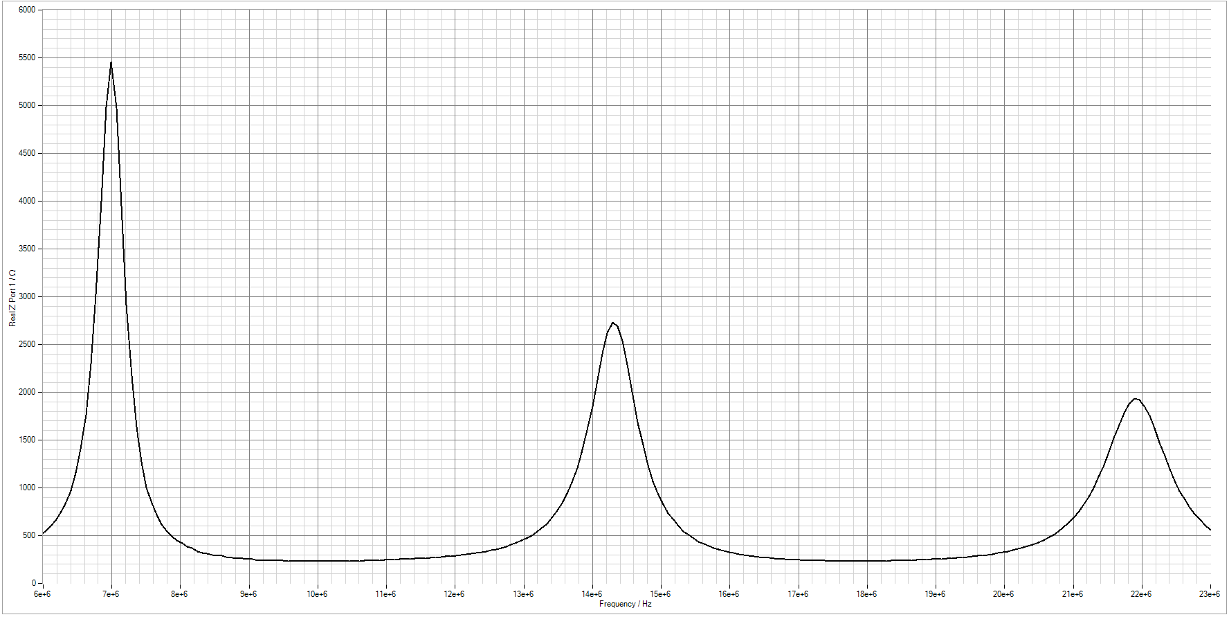
Suspecting a ground effect, I decided to measure the impedance, at 7 MHz, of the antenna without the transformer. To my surprise, it was around 6000 Ω! I then moved the antenna to different locations in the garden, but the impedance remained in the range of 5500 to 6500 Ω. This confirmed that the issue was likely due to the interaction with the soil composition and moisture levels.
Impedence measurement:
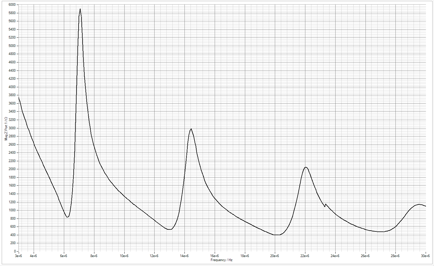
To match 6000 Ω to 50 Ω, we need a transformation ratio of 11. With 3 turns in the primary it’s 33 turns in secondary.
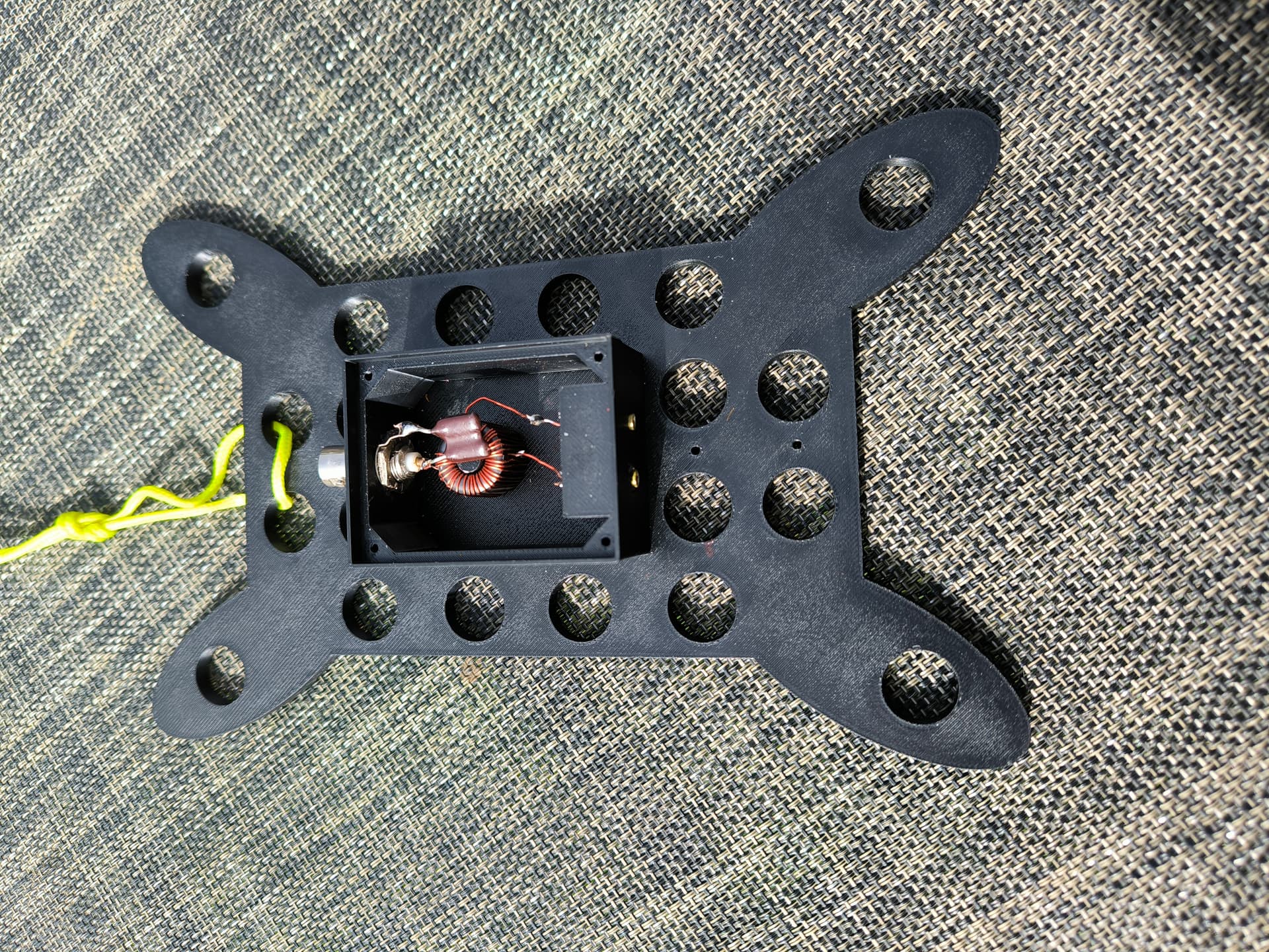
Instead of making multiple transformers, I designed a single transformer with a tap at 22 turns. This provides two different transformation ratios:
- Primary to 22 turns → ( 22:3 ) ratio → ( (22/3)^2 = 54:1 ) → Matches ~2700 Ω
- Primary to 33 turns → ( 33:3 ) ratio → ( (33/3)^2 = 121:1 ) → Matches ~6000 Ω

To test the transformer, I set up the following configuration:
- Antenna: A ~20m long EFHW, with the apex at 5.5m height and both ends at 1m above ground (forming an angle of approximately 125°).
- Coaxial Feedline: 3m of RG58 coax between the transformer and the VNA.
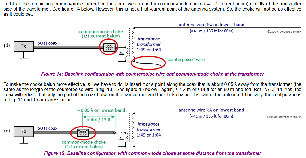
- Common Mode Suppression: A choke was placed before the VNA (I also tested without it, with no noticeable difference).
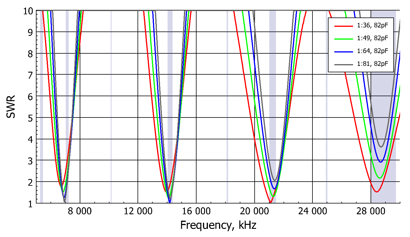
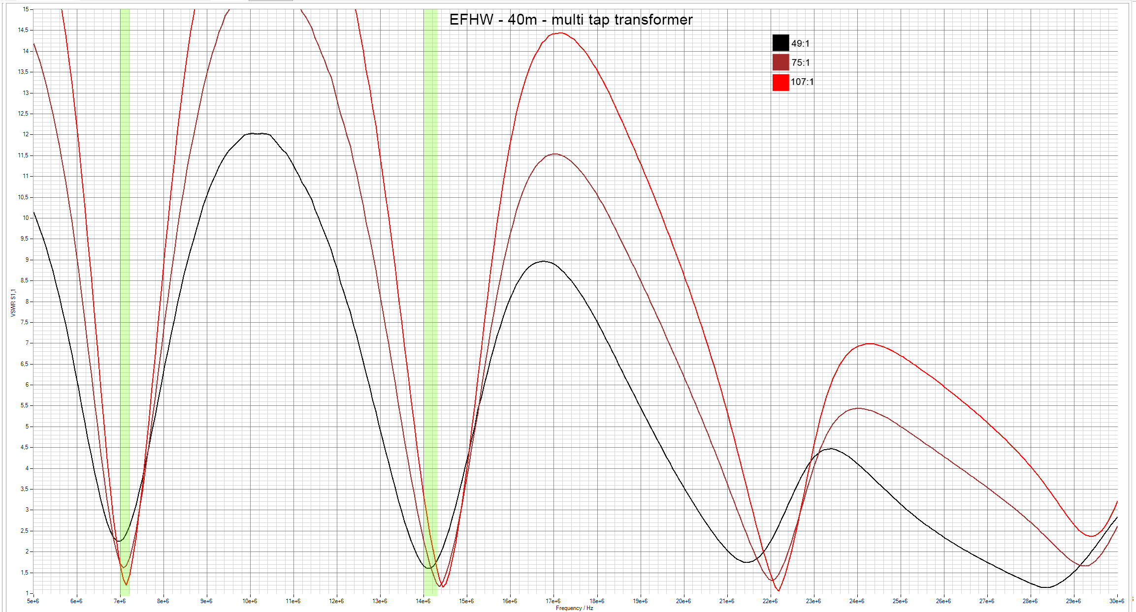
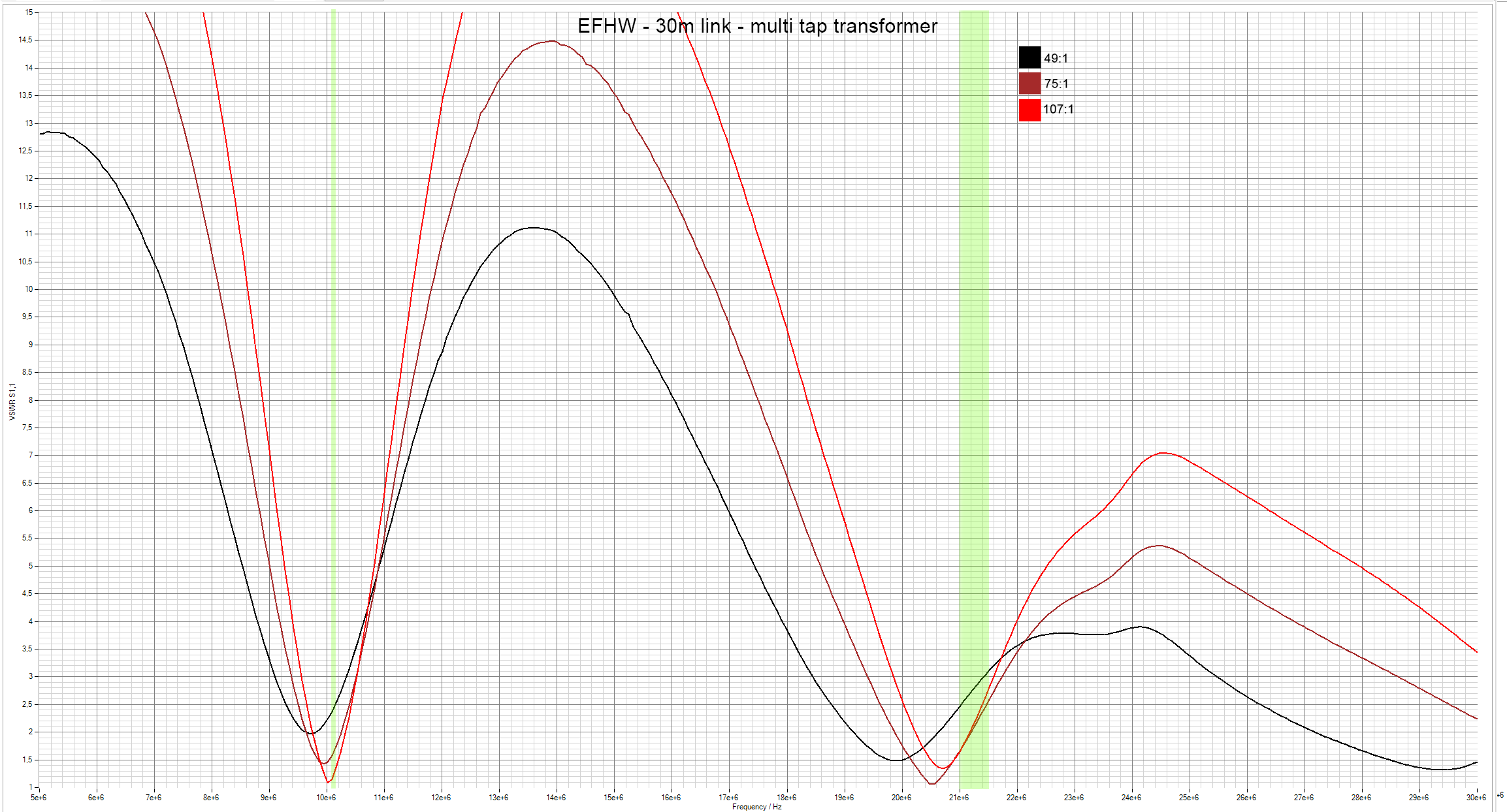
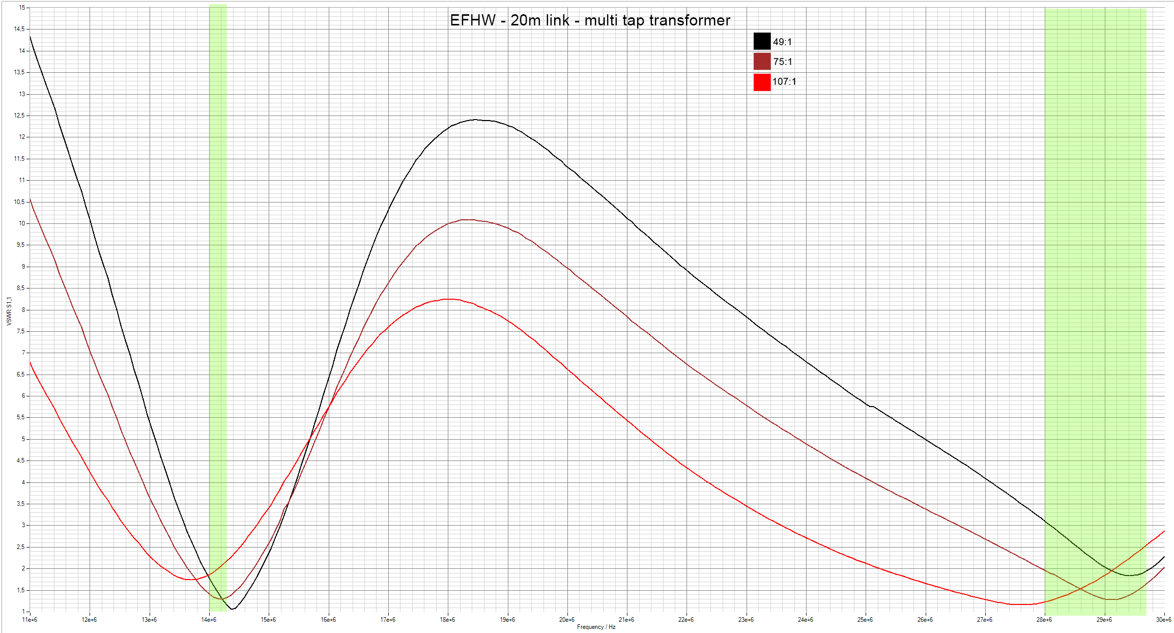
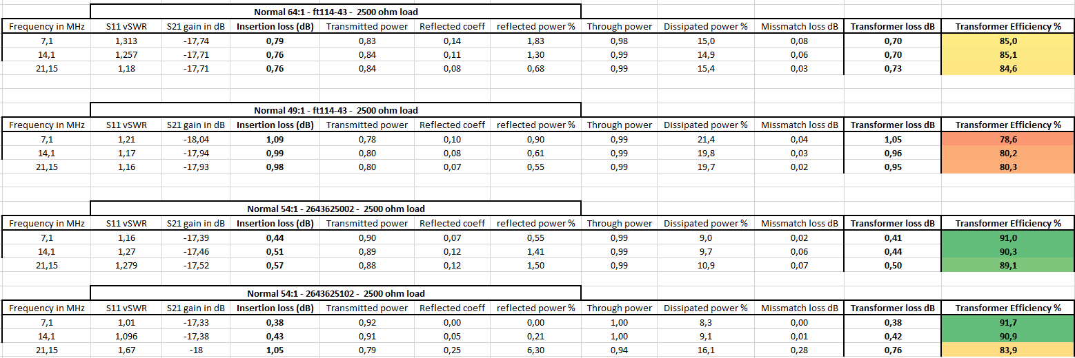
I measured the SWR for the following transformers:
- Standalone 49:1 transformer using an FT114-43 toroid (black curve).
- Standalone 64:1 transformer using an FT114-43 toroid (dark red curve).
- New variable transformer on position 1 = 54:1 ratio (red curve).
- New variable transformer on position 2 = 121:1 ratio (yellow curve).

When testing classic EFHW transformers (49:1 and 64:1), we can immediately notice that they are not ideal across multiple bands. If the antenna is cut to resonate at 7.1 MHz, it ends up being slightly too short for 14 MHz, causing a frequency shift of approximately 350 kHz on 20m. This behavior can be attributed to end effects, which occur due to the high-voltage nature of the EFHW antenna. The last portion of the wire interacts with its surroundings (insulator, ground proximity, nearby objects), introducing stray capacitance. This effectively shortens the electrical length of the antenna, shifting its resonant frequencies higher than expected. Additionally, the impedance transformer itself introduces some inductance and capacitance, further modifying the effective resonance points. Because of these effects, it is common practice to compromise when cutting an EFHW antenna. Many operators tune it to a preferred section of a band (e.g., the CW portion or the middle of a preferred band). Additionally, a compromise must be made on the transformer ratio, as the impedance shifts from 3000 to 6000 ohms when switching from the 20m to the 40m band.
To address these limitations, I tested a variable transformation ratio approach. This allows slight impedance tuning, which in turn affects both matching efficiency and the exact resonance points of the antenna.
Results
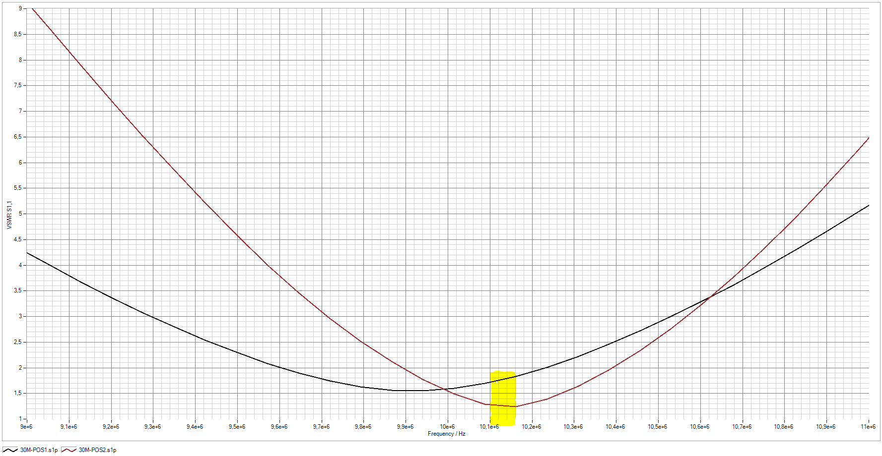
Using the 54:1 Tap:
- The resonance on 20m is well-centered at 14.150 MHz, with an excellent SWR of 1.2:1.
- The resonance on 15m is more than acceptable, with a good SWR of 1.5:1.
- However, on 40m, resonance shifts too low, around 6.920 MHz, leading to a high SWR of ~2:1 at 7.100 MHz—less than ideal for that band.
Using the 120:1 Tap:
- The resonance on 40m is optimized, with an SWR as low as 1.0 at 7.063 MHz.
- However, this tap is not ideal for 20 and 15m, as the resonance shifts undesirably, similarly to single ratio transformers.
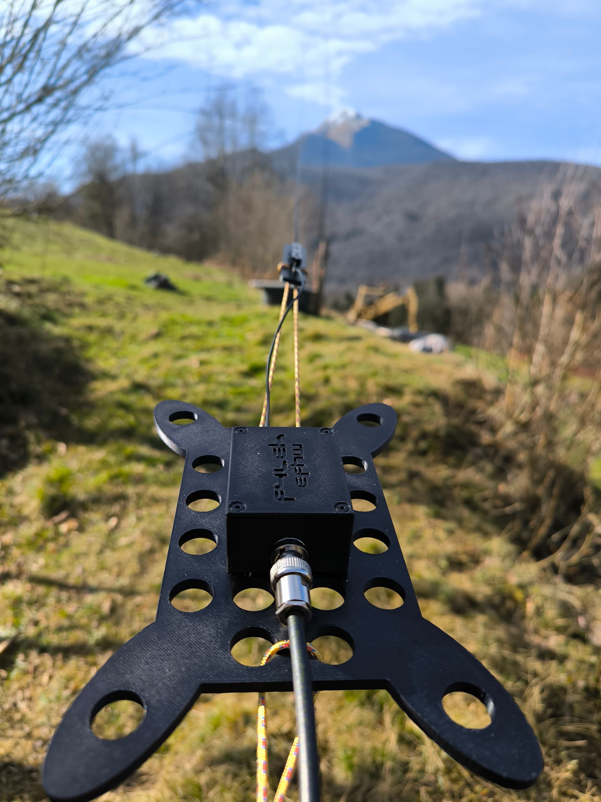
Not only does the ability to adjust the impedance transformation improve matching, but it also helps to fine-tune the resonance points to better align with the desired bands. To make this approach more practical, I designed and 3D-printed an all-in-one antenna winder and transformer case, integrating two banana connectors for quick antenna connection. This setup allows me to switch the matching ratio within seconds to better suit the operating band, providing greater flexibility in the field.
This experiment shows that a single fixed-ratio transformer is often a compromise, while a variable matching system can improve both efficiency and usability across multiple bands.
Further research is needed to explain why the 54:1 tap causes a downward shift in resonance points and how its behavior differs from a conventional, equivalent, single-ratio transformer. When using the 54:1 tap, 11 turns on the ferrite core remain unused. This may contribute to changes in inductance, stray capacitance, and coupling efficiency, affecting the resonance behavior compared to a single transformer with the same overall ratio.
The transformer:
The folded antenna:

The links and mast attachment pieces.

Open to discussion about this ![]()
Edit : post edited for better clarity and inclusion of latest results.
73, Rémy.