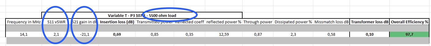
Sorry, Unfortunately I cannot follow the calculations and will show why below using a randomly selected table entry.
1 Like
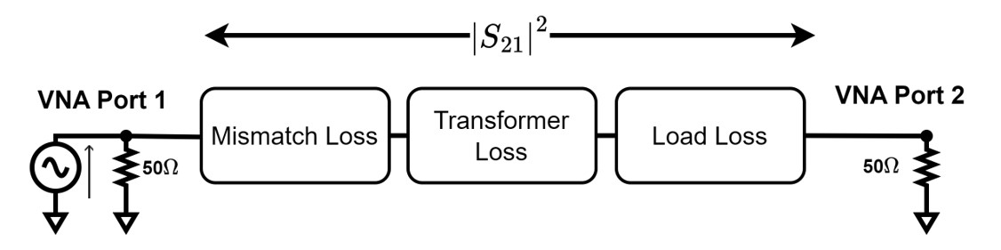
Ok, I think we’re just calculating two different things. Taking mismatch into account, you’re calculating the efficiency of the whole system. The transformer itself cannot be responsible for the mismatch, as you mentioned, that portion of power is ‘not seen by the transformer.’
In my calculation, efficiency is based only on the transformer’s losses. I should refer to it as ‘transformer efficiency’ rather than ‘overall efficiency’.
Edit:
I’m also confused by your calculation. I thought as:
- S21 = transformer loss + mismatch loss + resistor loss.
So
- Transformer loss = S21 - resistor loss - missmatch loss
In this case
- Transformer loss = 21.1 - 20.45 - 0.58 = 0.07 dB
Edit: I edited the Excel file for better clarity
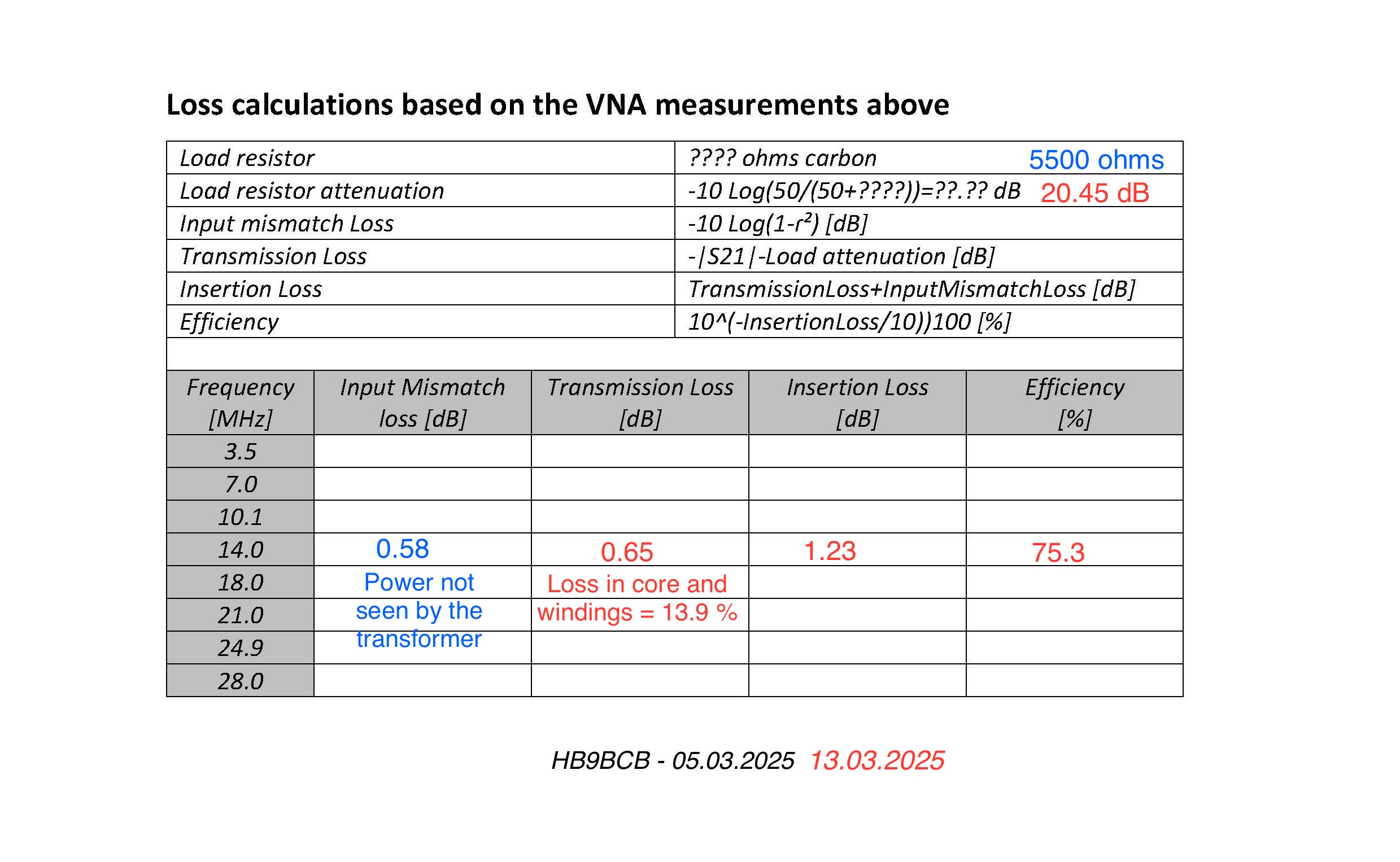
After a closer look at your example, I think you are counting the mismatch loss twice.
What you call transmission loss is:
- Transmission loss = S21 - load attenuation
And there, I believe transmission loss already includes the mismatch loss (it’s all the losses between port 1 and 2, minus the load attenuation), such as
- Transmission loss = mismatch loss + transformer loss
If you add missmatch loss to transmission loss, you count the mismatch twice.
Maybe ?
Edit: I found a post from you, where you explain it as I believe it is.
1 Like
Martin Steyer, DK7ZB, has also published and presented the design of an adjustable / switchable transformator. Although the explanantion is in German, pages 24, 25 and 32 show pictures which speak for themselves. According to Martin, there is no “one fits all” solution and he recommends switching to the most sutable tap for each band. However, I have never felt that this kind of perfectionism is really necessary during my portable operations with 10 watts. I followed Stephan, HB9EAJ, with his design and have always been pleased with it sinced I started to use it.
73, Peter
2 Likes
It’s definitely not necessary, I agree! Haha. It’s mostly for the pleasure of experimenting and exercising the brain!
1 Like
Sorry for the confusion.
As I mentioned in a PM a few weeks ago, an error crept in while editing an Excel spreadsheet, which is why I also recalled an EFHW transformer datasheet recently published on HB9SOTA.
And now, time passes so quickly and one ages unnoticed, I have uploaded an extract of this uncorrected Excel sheet and used it, unforgivable, sorry again.
The error only affects the calculation of the Transmission loss (Transformer efficiency), which should correctly be as follows: -|s21|-LoadAttenuation-MismatchLoss [dB].
When naming, I like to differentiate between the Transmission loss (-> Transformer efficiency), relevant for the heating of the toroidal core, and the Insertion loss (-> Overall efficiency), relevant to know for the user.
By the way, declared EFHW multi-band transformer efficiencies of >95% at VSWR values >2 still arouse my curiosity and motivate me to build a comparison transformer, in this case still pending.
1 Like
Ok, so we agree on that. This is what I’ve done in my excel sheet.
In theory, if you calculate the efficiency exclusively from the loss induced by the transformer, independently from the mismatchloss, it’s still possible to get very high efficiency at this level. However, I agree that 96% is very high and probably over estimated but maybe we should take it more like a relative comparison, since I measured all those values in one session, on the exact same setup and calibration.
Maybe something to clarify in my results is the difference in efficiency when using the same ratio but different resistors. How can the 49:1 winding show 0.53dB of loss at 7Mhz on a 2500ohm resistor and 1.27dB, at the same frequency, on a 5500ohm resistor ?
The same pattern is observed with the 107:1 ratio, it’s very good on the 5500ohm load but bad on the 2500. Maybe the impedance load has a real role in the performance of the transformer (different tensions / current according to the load = different losses in the core and wires … parasitic effects … ).
I will do another batch of measurements (and add an intermediate resistor load, like 4k ohm), to make sure it’s not a random experimental error.
1 Like
It could well do …
“Experimental Methods in RF DESIGN” by W7ZOI:
"A practical transformer will have a primary inductance with a reactance at least 5 times the terminating resistance at the low frequency limit "
This tends to be industry-standard practice. That said, ham radio experimentation often tests such guidance ![]()
73 Dave
1 Like