Hi Jim,
No I am not using 18650 individual Cells - I am using a complete single 3S Lipo battery solution. I am not using the Windcamp commercial solution, I am using a solution created in VK-Land by VK3YY and I took the connectors from one of my defunkt Yaesu NiMH (FNB-85) put that on my AA battery cell case and took its cable plus two 100k resistors(voltage splitter for the green "do not allow charging via the external 13.8v socket, lead) for the Turnigy Nanotech 2500maH LiPO battery from Hobbyking. I then put rechargable eneloop cells in the AA case. this pacjage with the eneloops last a LOT shorter time than the LIPO but it’s a backup. I would expect you may see the same with the 18650s.
As you say there are also commercial options from Windcamp and I think direct out of China if you wish to pay extra for the convenience but to manually do this is simple.
In my case I remove the battery to charge it so no changes are needed to the battery compartment cover.
I was hoping to use the 18650s just because I have them readily available, but this battery solution would be right down my alley. Do you know what the plug that I need is called? I want to buy a couple so I don’t have to pull any off my still usable AA or NiMH battery packs?
Hi Jim,
I could find similar plugs but not exactly the right one, so I looked around and bought an old Yaesu battery and took the lead from there. Then I swapped that with the lead on the AA cell box.
That green wire that tells the FT817 not to allow a charge to come back from the external socket (as is OK with the NiMH and rechargable AA Cells but not with LIPOs) - that is normally connected in the AA cells box at half way through the pack (something you don’t have on the 3S LIPO) - so instead of that you need to include a voltage splitter of 2 x 100k resistors in the cable harness.
Apologies for resurrecting this thread but from the comments it seems that some of you may have an idea of what is causing my problem with the FT-817. Basically, it will no longer allow me to start the charge timer (6h or 10h) - all I get is a double beep when trying. The radio works fine off the external DC and also works from the internal battery, which continues to trickle charge if I leave the external power on. It just means that I have no means of fast charging the battery. I have tried a factory reset, but that did not fix the problem. I tried varying the voltage from the external supply which did not fix it either. It is almost as if something is telling the CPU that there are alkaline cells fitted (or no battery) and so it is refusing to charge. I have looked at the circuit diagram in the service manual but I can’t figure out where the fault may lie.
It was working until a few weeks ago - I haven’t knowingly changed anything on the rig…
Read up about the FT817 Green Wire Mod. This wire is used to stop the 817 from charging AA cells in the disposable battery box. Many owners do the mod so they can charge high capacity AA NiMH cells in the radio. It could the wire is now disconnected.
The green (BATT) wire is connected to V+ to stop charging. (it is open circuit, or you could ground it to enable charging)
Only 6.5uA is needed to stop charging. If the voltage on the green wire is >0V to ground there is something wrong. It will stop charging at >2.4V)
Assuming your green wire is not connected to B+, then you might have battery slime that has crawled its way down the cables, and is bridging the green wire to the adjacent B+ pad. (on the pcb, or doing the same in the plug)
On mine the battery slime had already eaten the pcb away, I could easily imagine it tracking 6.5uA across.
(btw, any sign of green at the battery connector, and you should replace the whole wire back to the pcb, and clean the pcb around the cables)
The green wire is not connected to the voltage+ line - it is connected halfway through the battery pack (so at ~ 5/6 volts). If you wish to use the green wire to stop external charging when you are using for example a LIPO pack internally, I recommend fitting a voltage divider to feed the green wire. A pair of 100k or 10k resistors is all that is needed to create the voltage divider.
Interesting. I don’t have one, so assumed it was connected to V+
I recommend fitting a voltage divider to feed the
green wire. A pair of 100k or 10k resistors is all that is needed to create the voltage divider.
There is a 300k resistor sensing BATT, so no reason to have a voltage divider. (certainly not 10k’s that would leak 600uA)
Hard to see why Yaesu tapped the battery pack.
Easier place to connect the green wire? Shorter green wire? Bit less leakage current?
If you want to use rechargeables just cut the green wire and use the battery pack.
It is very unlikely that any user of an FT817/8 would use alkaline except in the direst emergency - and they would still work with the wire cut
Rather than cutting the green wire, and assuming you want to maintain the integrity of the battery carrier … just ease the green wire terminal out of the connector. It’s a bit fiddly but do’able. Outcome: If you ever want to sell the 817 then you just re-insert the green wire and you don’t have a ‘butchered’ example of this great little rig.
Thanks for all the replies - I wasn’t expecting that many on a resurrected thread!
Update: I am using the AA tray with rechargeable NiMh batteries in it, but also have the original battery (which has reduced capacity but still works). I had already removed the green lead from the plug as M0XPO suggested (a good tip!).
There is no sign of the green slime, but I will look carefully - in any event, grounding the lead may also help eliminate things - I hadn’t thought of that!
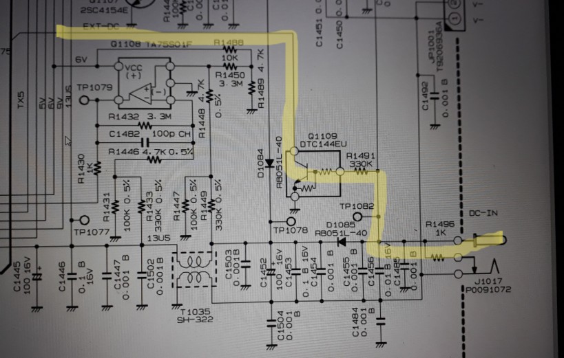
I am also using this as a way of learning about the circuit and how it works. I can see that the presence of a voltage will turn off the charging (both to the trickle charge circuitry and to the BATT input on the microprocessor) but I can’t work out what happens to the voltage on the OR gate (D1085) as it seems to be used back to front - it looks like it is expecting a signal coming from the CPU, not going to it?
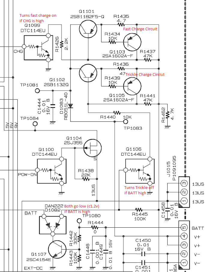
Yes thanks - the only thing that isn’t working for me is being able to start the charge timer. I can run on external or battery power and the trickle charge circuitry is still working. I have also had a powerpole adapter fitted for the last 2 years so I don’t think that is the issue. I think the issue is somewhere between where the BATT detect output goes into the main bus and where it comes out as CHG, which turns the fast charge circuit on. As the CPU won’t start the timer (double beep), it looks like BATT is being held low somewhere?
NiMH battery pack installed, no 12V power applied, press the button to start charging = you get the beep plus two shorter beeps (i.e. an error) and no charging.
NiMH battery pack removed, external 12V plugged in, press the button to start charging = one beep and the charging icon shows up even though there’s no battery plugged in.
So it’s strange that you can run off external power but the controller thinks you are not.
What voltage does the 817 show on the display when you are on external power and is it what you expect?
D1085 on my schematic is just a diode in line with the power supply and looks like reverse polarity protection. Make sure you’re looking at the right schematic for your model, there are multiple lots/revisions of the board. Mine has F1001 for example whereas some earlier versions do not.
I would start by checking this part of the circuit on my diagram. If you have the circuit board out have a check for any damage here, blown tracks, corrosion etc.
Thanks this is really helpful. The voltage shown mirrors the voltage from my PSU. I tried varying it between 10v and 14v to see if that was a factor. If I take it off external power it then shows the battery voltage - typically 10.2V falling to 9.6 over a few minutes.
D1085 was a mistake - I was reading it from the diagram earlier in the thread, which is mirrored and so i miisread a 2 as a 5 - it should have been D1082. I haven’t taken the board out yet, but all looks normal with nothing looking distressed on the top side. The diagram for my rig, with my annotations trying to understand what it is doing is attached.
__BATT goes to the cpu only where it has a 330k pullup R4011. (I will call this __BATT to differentiate from the BATT green wire)
As it is pulled low to disable charging, a broken FFC to the panel would enable charging, so it is not a break.
D1082 is not acting as an or gate. It isolates the cpu BATT line with its pullup, from the external power sensing R1445 that enables trickle charge with external power. Without D1082, __BATT would be held down by Q1106 base.
If you have the backlight timer on (i.e. backlight turns off on battery) then you can tell if the '817 thinks it has external power: the backlight will stay on. If the backlight goes off when on external power, then the cpu doesn’t think it has external power, and that is your problem.
If you are pulling the board out, then a small mod I have done on the underside is a p-fet across diode D1084, to claw back 300mV of battery voltage.
BTW the manual on the net is quite a bit older than my '817ND and pcb layout differs significantly in many places, making it hard to locate test points and so on from the top side. If you need to probe bottom side voltages, you can solder wire wrap wires to the pcb, and solder the other ends to some veroboard with a line of pin headers. Then put the board back in.
Thanks for the help - I have now had time for some probing. You are correct about the backlight - it is turning itself off on battery power and external power, so the CPU thinks there is no external power applied.
The voltage on the input side of R1491 is 12.6V and on the output is 2.05V. The voltage on the output of Q1109 is 9.4V with external power in place and increases to 10.65V when on battery power. All this is with the Rig turned off.
With the rig turned on and on external power, the front display is 12.4V, and I get 12.5V and 2.1V across R1491 and 2.2V on the output of Q1109.
The resistance of R1491 with the external power removed and rig off is showing as 7.6k ohm, not the 300k expected from the circuit diagram.
My knowledge of troubleshooting circuits is still at the learning stage, but it seems like the switch transistor is still working but isn’t putting a high enough voltage out for the CPU to register there is external power?
So Q1109 has 47k resistors internally.
We expect 2.13V at the end of R1491 if the base-emitter junction is OK, and 2.8V if it is open circuit. So the BE junction is OK, and thus the the collector voltage should be ~0.2V
Using your multimeter on the currrent range, connect Q1109 collector to ground.
It is pulled up with 47K, so there should be ~250uA current. The backlight should turn on as the mete5r is connecting it to ground.
If so, Q1109 is dead. You can just connect any npn transistor eg BC547, 2N3904 across Q1109, and it should work.
If not …
The resistance of R1491 with the external power removed and rig off is showing as 7.6k ohm, not the 300k expected from the circuit diagram.
That’s not consistent with the voltages you have given. Priob not measuring what you thought.
As an aside, when measuring in circuit, measure using the meter both ways ie reverse the probes. If you get the same value, then you are likely to be measuring R, if it differs, then there might be a diode/transistor junction there. R is likely to be the higher of the two values.