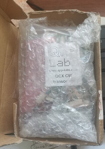
i still have a qcx in kit, still in box, never been out of the bags. I may build it one day, but i know i probably won’t lol.
Which band? Which QCX (classic, plus, mini)? Does it have a case?
classic i believe. no case, 30m it was bought for when i learnt cw, i dont stick at it long enough to learn cw and i never really build anything, i may start or have good intentions but its easier to just buy it ready made lol. I have checked my email and its serial number 2787.
I’m a little further than Anthony @M0VED ![]()
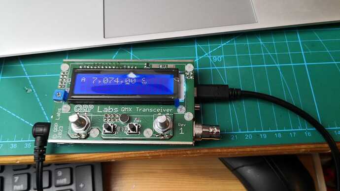
I have built three QCX’s (2 classic and 1 mini), and currently I’m building a QMX for a friend (I have enough small QRP rigs for now … hi).
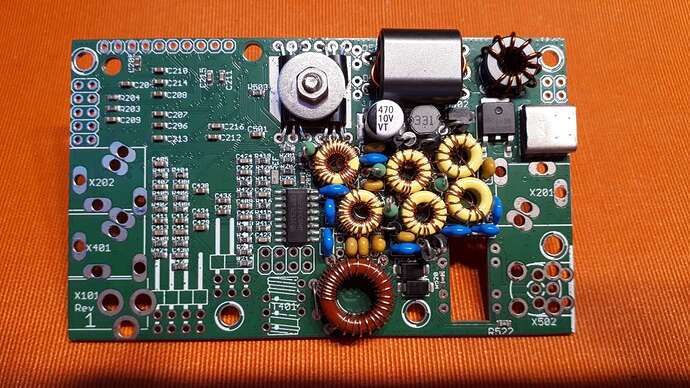
It’s looking good so far …
TIP : I had to put less turns on all 6 yellow cores, 80m & 60/40m: -1, 30/20m -2 , to obtain the correct inductance. I had to do this on all my QCX’s as well.
I hope to get it working before next monday , when it’s the QCX (&QMX) WARC band QSO Party (QCX WARC Party ).
73,
Luc ON7DQ
Hello Luc,
That is generous of you to build the QMX kit for a friend, good work.
You don’t mention if you are aware of the re-design work that was published by QRP Labs on July 8th and I thought I should mention it, just in case. It involves the 20m band and cures the poor receiving sensitivity. The information is published on the QRP Labs web-site, and was discussed in detail in the qrplabs@groups.io discussions.
The QMX sounds as if it is a work in progress, with several problems and fixes on going.
Ian
VE6IXD
Hi all
QMX, the hardware is working fine, there was an issue with 20m sensitivity due to a parasitic resonance notching at about 14MHz but that is resolved now. It was documented here 20m sensitivity modification and it is now in the official manual.
Firmware is an ongoing work. The radio is an extremely powerful and high performance hardware platform. The initial firmware basically works on CW and Digi modes but there is still a lot more to come!
Hannes DL9SCO and I went to a “summit” in our YouTube video QMX portable CW ops with Hannes TA4/DL9SCO and Hans TA4/G0UPL - YouTube but unfortunately since Turkey isn’t in SOTA, it’s not a SOTA activation. QMX was great and we worked 10 countries between us fairly easily. The video shows a very load key-click in the audio but this has been resolved by a firmware update a few weeks ago and QSK is extremely smooth and quiet now. The CW envelope shaping uses Blackmann Harris which has an even higher performance than raised cosine or Gaussian shapes. The Transmit/Receive turnaround latency is around 15ms which compares very well with respected radios like Elecraft rigs.
With low cost, high performance, 5 bands, CW and Digi (and in future, SSB), low weight and low 80mA Receive current, I think QMX will be the perfect SOTA radio. Certainly SOTA and portable operations were forefront in my mind while I was designing it.
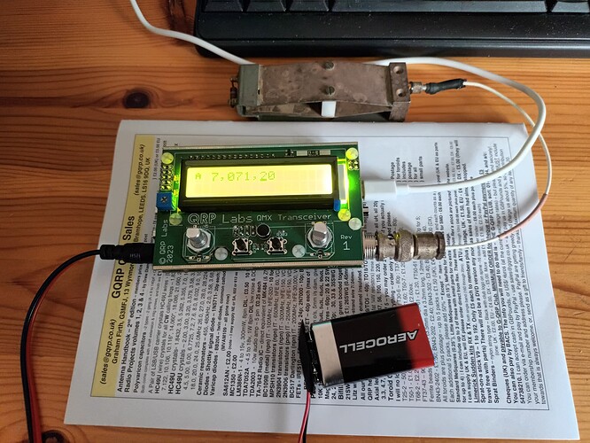
QMX built, first QSO completed on 30m. I’ll probably play with it a bit more before taking it on an activation.
Pleased so far, though!
I just released a new firmware version, CW message memories are working now in 1_00_006 see QMX multi-band transceiver kit
73 Hans G0UPL
Congratulations on the successful setup and the first QSOs with it. My kit is currently still waiting at customs. Looking forward to the assembly.
73 Marcel DM3FAM
Hi everyone,
I used the recent bad weather in Austria to finish my QMX. It came to life no problems after uploading the firmware. Very simple and a great improvement over the QCX series. Power out was around 4 watts (at 12.3v), only creeping up to 5 on one band.
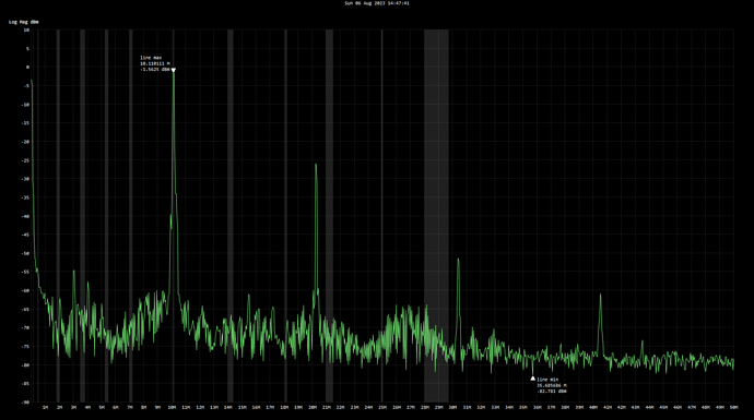
I just wanted to inquire about the LPF toroids. Are other hams adjusting for max power out / harmonic suppression? I took a snapshot today on 10MHz and found that the second harmonic was a little high:
I didn’t want to bother Hans with it, it sounds like he’s hellish busy at the moment.
73 de OE6FEG
Matt
Hi Matt,
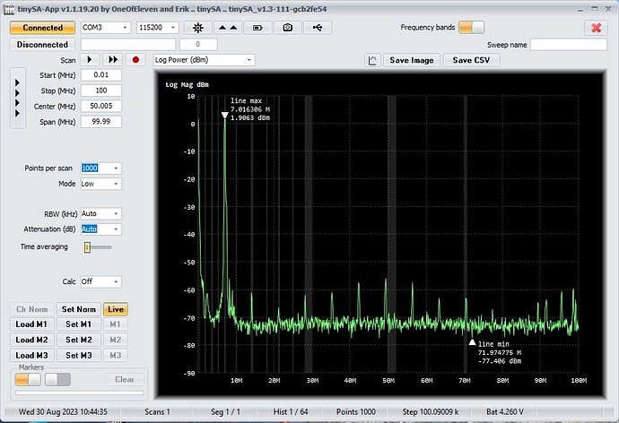
I haven’t tweaked the toroids in mine. The built in scans were not perfect, but typical of those posted in the groups.io forum.
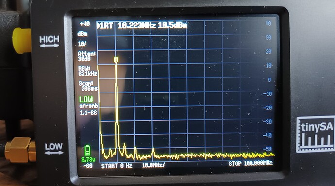
This is how mine looks on my TinySA, output 3.5W on 12V supply. Connected to SA via 30dB attenuator:
I first tried looking at it just using the whip antenna on the SA near a leaky dummy load, but the higher harmonics looked grim! Lots of unknown variables in the coupling, I guess.
Edit: I think the second harmonic should be suppressed to some extent by the push-pull output stage, I wonder if you have an issue around the PA stage…?
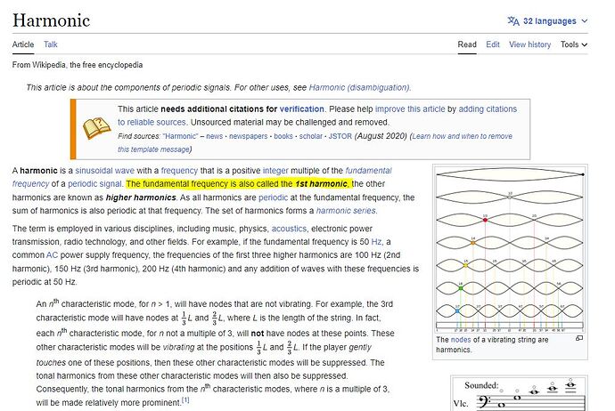
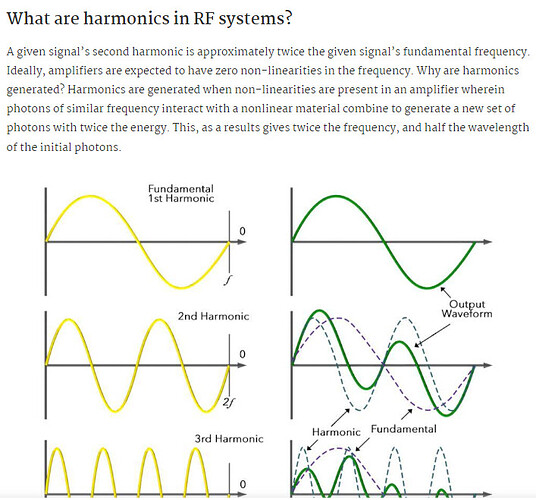
From your graph, I assume that you refer to the first harmonic at ca. 21 MHz for the 10 MHz fundamental (30m).
That is kind of strange - as the QMX uses a symmetric push-pull PA (similar to the one in the QDX), the level of the first harmonic should be fairly low even without any filtering. My guess would be that there is something wrong other than the LPF, e.g. one of both sides of the PA not working with full power or some phase issues between the two driving signals.
One of the key cool things about Hans’ QDX PA (and the QMX) is that the inherently low level of the first harmonic makes it possible to use one LPF for two bands. This only works well because because the first relevant harmonic is the 2nd (3 times the fundamental) and hence far away from the fundamental of the higher band that shares this LPF.
Example: 40/30m LPF
40m: 7 MHz fundamental, 14 MHz 1st, 21 MHz 2nd
30m: 10 MHz fundamental, 20 MHz 1st, 30 MHz 2nd
The LPF does not need to attenuate 14 MHz too much, hence it will not produce big losses when used for 10 MHz (limited steepness of feasible filter designs).
With another PA design (e.g.) as in an MTR or QCX, it is hard or even infeasible to design a common LPF for two bands. You would hence need (more) relays, slide-switches, or a more complex diode-based LPF switching circuit.
73 de Martin, DK3IT
Edit: @G4AZS added a similar hint while I was writing this post ![]() .
.
Edit 2: My prime suspects would be
- cold soldering or shortcuts on some BS170s,
- stray capacitances at the input of these (e.g. too long wires),
- cold soldering at the driving logic gate (e.g. only one of the two gates actually driving one of the BS170 pairs),
- problems with the split winding of the output transformer (miscounting the center tap, broken isolation of the magnet wire, …), or
- one defect BS170.
The PA design is really nice, but it is essential that both sides of the push-pull circuit work in good symmetry. And the paired BS170s driven with a logic gate (same as in Steve Weber’s and many other designs) is also kind of a (field-proven ;)) hack that works, yet is sensitive to additional gate capacitance.
Edit 3: A misplaced (wrong part) or broken diode D504 or D503 could also cause such behavior.
The spurious radiation clearly exceed the strict legal requirements of -50db at 1.8-29.7MHz. Here it is almost -60db. I see no need for action there.
73 Chris
Hi Chris,
I agree of course! I’m happy with my QMX output.
I didn’t make it very clear, but my comment below referred to an earlier attempt at measurement using a bad method. I only mentioned it in case it helped others to avoid the same mistake…
I got in touch with Hans and he suggested that what I was seeing could be an artifact from my measuring equipment. It’s interesting to read that you got some high readings as a result of coupling. When I retested today, all the bands were clear with harmonics well below -50dB.
I sent the scans to Hans with a description of the setup; fingers crossed, it was just a glitch in the measuring. Thanks for the input everyone. I need a lie down now, it looks like I actually made something that works first time. ![]()
73 de OE6FEG
Matt
Hi Martin,
actually, I was under the impression that the fundamental and the first harmonic are exactly the same; so 10MHz in my screenshot. I meant the second harmonic was at ca. 21MHz. That is in keeping with what I read online, have I misunderstood something?
73 de OE6FEG
No!
73
Rod
Hi to all,
I use 3 QCX mini for 2 years, and the QMX should be a good new choice for me. But reading the QRP Labs forum, I am a little frightened by the number of smoked units. Any comments or experience?
73 Nico
I have a 40+ year career in electronics and software, I’ve built lots of electronic items for both career and hobby. Many of the people building QRP Labs kits have very little experience of construction never mind the quite small components in these kits. I think the build instructions are some of the best I have ever seen which goes a long way to helping inexperienced constructors build a working product. But you will be dealing with people who have limited experience. Also lots of people “know better” and when the max voltage is given as 12V decide that must mean 13.8V as it usually does and it doesn’t! Also the comments about using a well matched antenna are not always adhered to, people will use any old piece of damp string ![]() What that means to me is a lot of the issues come from lower levels of experience building equipment and failing to understand the real-world limits of the system.
What that means to me is a lot of the issues come from lower levels of experience building equipment and failing to understand the real-world limits of the system.
Add to that there is lots of build issues on the QRP Labs website because that’s the place to go for help. Most of the success stories are not on there and that gives a distorted view of any problems.
Would I buy a QMX? I just checked and I have 10 HF transceivers so I cannot justify one right now though it would be nice. Also, I’m quite selfish based on my experience of first-release items both professionally and in my hobby. So I will leave the must-have early adopters to help work out any production issues and I’ll buy a second or third run device.
I shall follow Matt’s comments carefully to see how his QMX works out in what will be a real-world severe environment of SOTA activator use.
EDIT: make that 11 HF transceivers!
Firstly, I would watch the new video Hans has made:
To that excellent advice I would add the following:
A Dremel is extremely useful for stripping enamel from the thicker wire used on some transformers. It also helps with reshaping some components, like 3.5mm audio sockets, if you don’t get the alignment quite right.
A bit of extra flux might help keep things tidy in certain tricky spots. I noticed filaments of solder going where they shouldn’t when soldering mine.
EDIT: Some leads are better trimmed flush with the board and then soldered. Also, consider a clip and remelt soldering pattern to avoid cold joints.
Don’t try to do too much at once. You can end up quite frazzled after 4 hours solid on this project. The following workflow is roughly what I did:
Day 1: read manual, inventory, wind toroids & strip enamel.
Day 2: solder caps, diodes, inductors & transistors
Day 3: solder toroids
Day 4: solder connectors & buck converters.
Day 5: solder contol board, assemble & test.
This is certainly not a beginner’s project, so maybe build something simpler if this is your first build.
73 Matt
