I need you to get to the bottom of the issue here so I can learn from whatever you did and not do that when I biuld the QCX30m I have here sat in a box.
The QCX uses a bog standard Low Pass Filter designed with 50 ohm input and output.
The KD1JV MTR LPFs use an input impedance of 10 ohms.
The MTR and QCX PA stages are extremely similar.
@G4AZS, I’ve heard that lots of experienced builders have struggled with power output, I’m inclined to think that both of us have built the rigs correctly. I reckon that tweaking the inductor nearest to the PA stage will improve power output. I also reckon that remodeling the LPF to present a lower input impedance will bring the power output to more like the expected 5W level.
I measured all of my inductors and they were exactly at the right values.
That’s my feelings/findings tonight!
Colin
Power before the change was 4.2 Watt, also at 16.8V (before the protection diode).
So an increase of some 0.8 dB.
I take 16.8V because I use a 4 cell Li-Ion pack, which has that voltage at fulll charge.
73
Luc ON7DQ
Hi Colin @M1BUU
Not just me then, phew!
I’ve stayed with the supplied toroid cores. They measure low in inductance on my Peak LCR meter, but using my home brew meter, they measure correctly. The Peak isn’t giving consistent results either - something else to investigate!
Progress so far:
Reading the instruction manual, I checked the waveform at the output mosfet drains, and found that the amplitude increases as I reduce the frequency below 10MHz (still increasing as I get down to 8 MHz) With 13.8v supply, the peak amplitude is 48v at 10 MHz, and 61v at 8 MHz.
This suggests that it is not just the LPF which is out of kilter. So, I have removed a couple of turns off L4. It is still tuned low, I think, but somewhat better. I’ll leave it at that for the time being.
(L4 is what I would think of as the “tank” circuit for the output stage, and the manual suggests that the tuning of this is not critical, but involved some experiment at the design stage, to take account of the capacitance of the mosfets - so I thought a little more experiment might be in order) 
I then removed a turn off each of the LPF toroids, L1, 2 and 3.
These changes have increased the output, but there is still room for improvement.
If I have time today, I’ll do another frequency run from 8 to 11 MHz, and compare the results with my earlier test. That will give me an idea of what to do next.
Thanks for your comments comparing the MTR output design - interesting.
None of my comments are meant as a criticism of the kit - the manual is really informative, and the circuit board is large enough to allow changes and measurements without too much trouble.
I’m having great fun, but must get out on a summit before too long…
Luc @ON7DQ - thanks for the feedback, interesting.
73
Adrian
G4AZS
Having had contact with a few builders of the kit, our results are pretty much typical. I really believe that there isn’t a build fault, it’s how the circuit is.
IMHO, removing turns from the toroids is a bit unscientific.
Hopefully I’ll find some time later on to have another look at the rig.
73, Colin
Not really unscientific, it seems that all coils are too high in value if you follow the manual.
I was inspired by reading this Inductance of the QCX 20m low pass filter inductors
and indeed, all of my coils had also the same high values. I wish I had measured them before mounting, it was a lot of trouble getting them out, remove a winding, and putting them back in.
As for L4, it is critical. Class-E amplifiers are not easy to understand, but there is this spreadsheet that should make things easy if you want to roll your own …
http://www.wa0itp.com/class%20e%20design.html
Anyway , now I can put out a neat 5W of power. Hope to get a use for the QCX on my Gran Canaria trip in april/may.
73
Luc ON7DQ
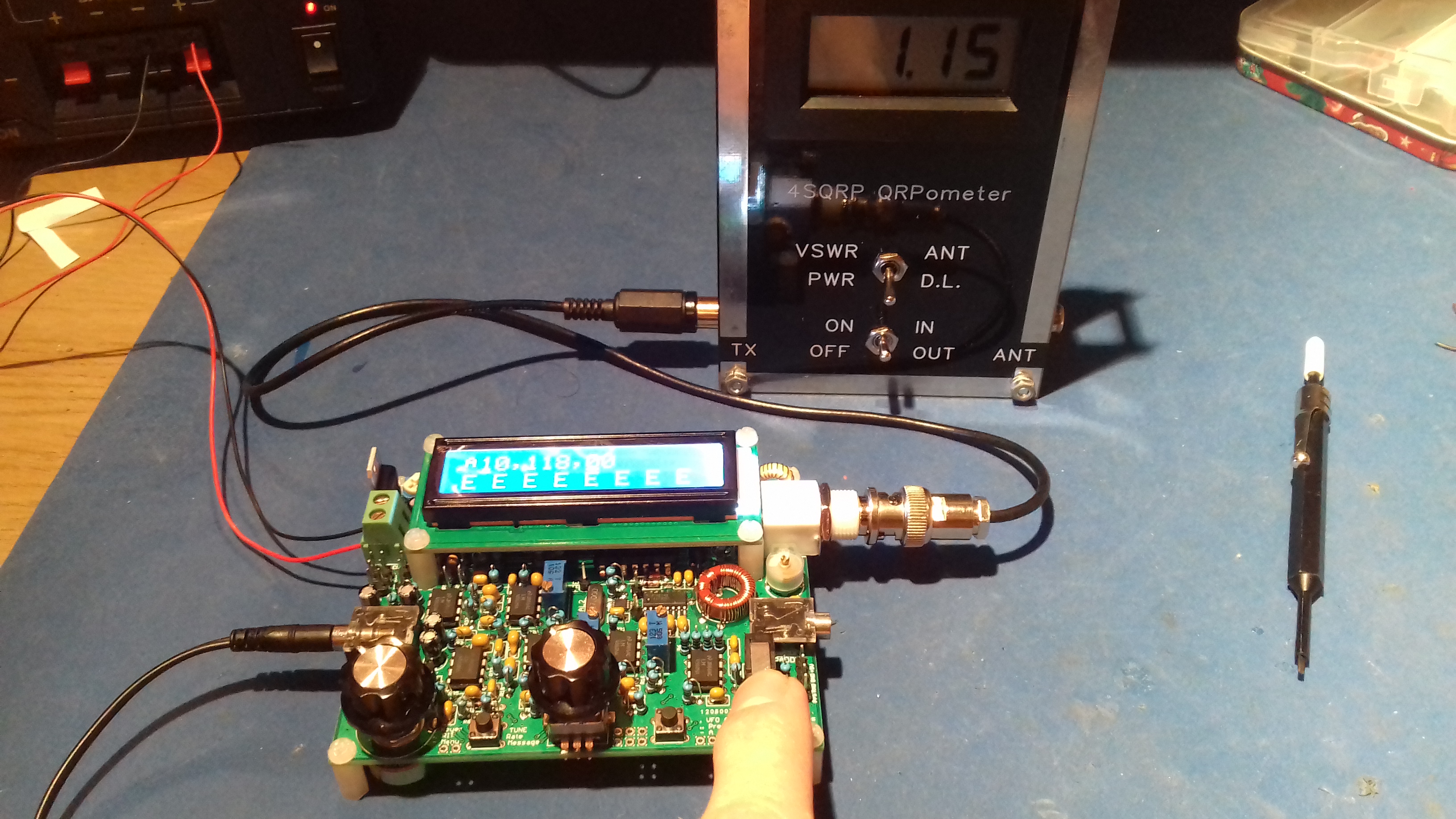
It’s definitely the low pass filter values. I modified the LPF and now I’m getting > 4 watts at 13.8V.
Adrian @G4AZS you can be reassured that you’ve done nothing wrong. Now that I’ve taken a ‘look’ inside my brain, I remember that I had an email discussion about the G-QRP design of low pass filters some years ago with a knowledgeable ham and the outcome was that the filters cut off a bit low in frequency, causing loss at frequency of interest.
73, Colin
2 Likes
Hi Colin,
I have only 710 mW output at 12 V. It is the 30 meter kit.
What did you modify ? Maybe it can help 
Colin @M1BUU thank you for the update!
I have removed 1 turn from each of the 3 LPF toroids - that levelled the output across the 30m band, where originally, it was dropping off as the frequency increased. But the output is still only 1W.
What changes have you made to yours, please?
On the plus side, I have just had my first QSO with mine, Carlos CT1GFQ/P 559 both ways, though with much QSB 
73, Adrian
2 Likes
I didn’t touch L4.
I removed the W3NQN filter and replaced it by another low pass filter design.
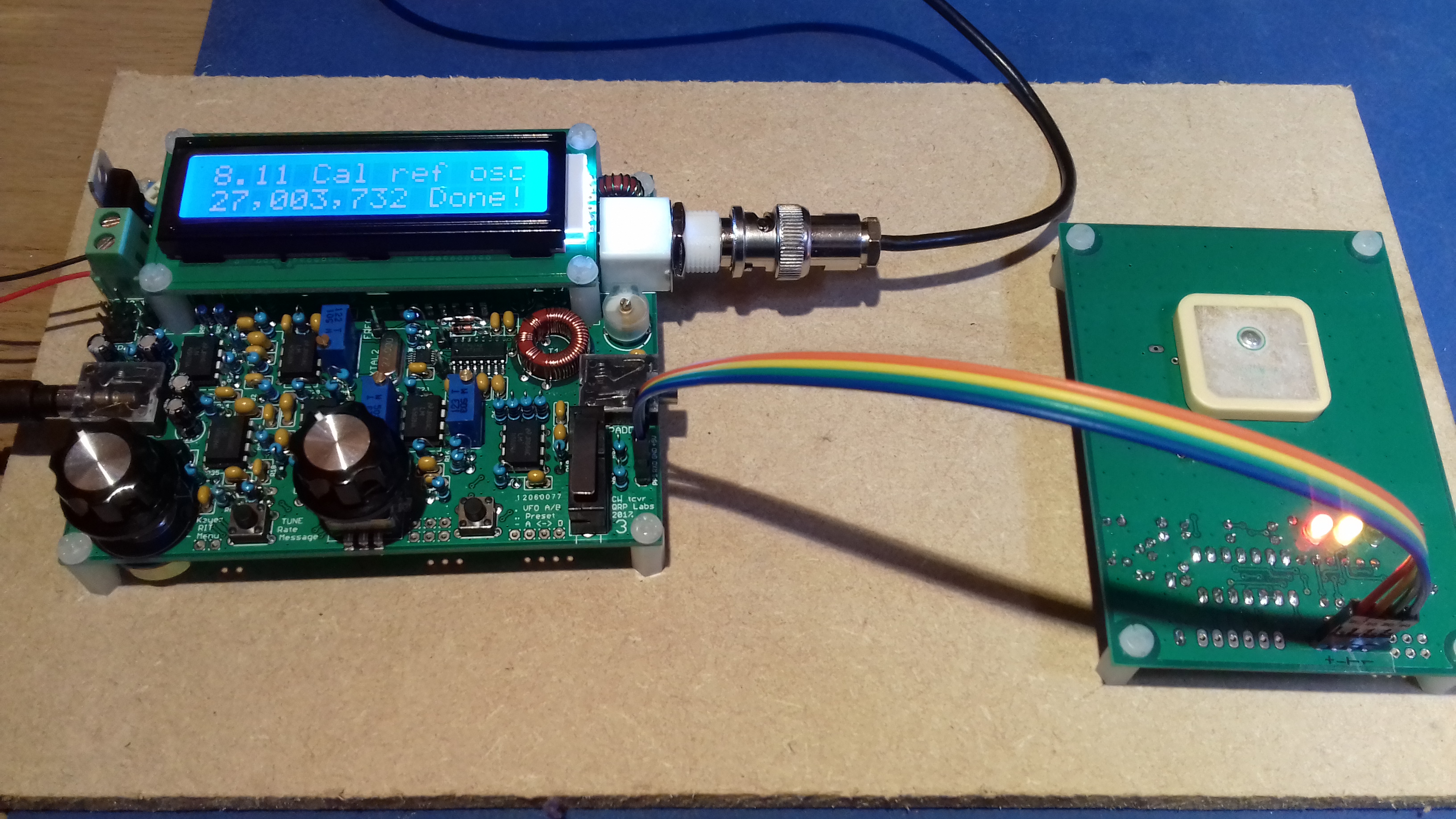
This afternoon I have calibrated the oscillators using the GPS.
I’m almost of the opinion that there’s too many features on this rig! 
2 Likes
Me too, until I learned that it is not possible to transmit while RIT is turned on! ![]()
Hi Colin,
Nicely done!
Good call on L4 - I decided that changing that value was a bad idea, and rewound it to the design. It suddenly occured to me that increasing the peak voltage at the drains to 62 volts (that’s what happened when I reduced the value) couldn’t be good, as the BS170 max voltage is 60v…

I also bought the GPS board, but I haven’t started on that yet.
There are plenty of things to play with, very impressive
Yes, there seems to be a few ‘quirks’ in the FW.
My rig has firmware rev E and when the GPS is connected, the rig goes into transmit. I discoved this after connecting the GPS with no load fitted! My PA seems fine though, I guess, like the MTRs, transmitting into an open doesn’t seem to matter.

I’ve had the GPS module and it’s partner the SI5351A based VFO for a while, it’s the nearest thing that I’ve got as a frequency standard. Before I got the GPS locked VFO I was using a Chinese TCXO module intended for fitting into an FT817! The RBN is also quite useful for a ball park figure, although a few skimmers seem to be slightly off.
1 Like
I like the idea of a gps locked wspr tx on hf. Bit over cooked for regular cw usage though!
Next a gps locked stopwatch to time your runs up hills. Gotta be accurate.
1 Like
Hi Andrew, yes, wspr is supported by the QCX (eg the firmware handles the timing and messages etc), it just needs the gps module for accuracy. As I haven’t yet dabbled with wspr, it seemed a good opportunity to play!
I am going to fix this… issue with how RIT is used. In the next firmware revision…
73 Hans G0UPL
1 Like
Transmitting while the GPS is connected is normal, because the 1pps and Serial data signals are shared with the paddle. Limitation of how many I/O pins are available! The intention is that the GPS should only be used (and connected) for calibrating the radio, and when using it in WSPR mode.
73 Hans G0UPL
Thanks for the explanation Hans.
I had hooked up the GPS purely for calibrating the oscillators but I noticed something was happening as there was a ticking in the headphones and I saw the current meter dancing. Anyway, the calibration seems to have gone OK, the frequency of the QCX agrees very closely with my FT817.
Aside from the low pass issue, I’m very happy with the kit, I’m going to enjoy playing with some of the many features
73, Colin