Hans Summers, G0UPL, has made it very clear that the QMX should not receive more than 12 V.
I am looking for a compact, lightweight low-dropout or buck‑boost voltage regulator (kit or preassembled) to power a QMX from LiPo or LiFePO4 batteries. It should provide 12 V output at 1 A from an input of 12–16 V. Optional support for 12 V from a 5 V power bank would be a plus but is not strictly required. The regulator must be quiet across all HF frequencies.
Preferably, it should be available from suppliers within the EU.
Has anybody found a suitable regulator circuit? Any hints welcome.
Heinz, I think this was discussed here suggesting a LM1085IT-12 IC. Not the most efficient compared to buck-converters I guess but probably quiet enough.
Since 12V is optional in the latest version of the USB-PD specification, make sure your power bank supports it.
In order to make sure that I always have 12V available no matter how the spec changes and what power bank manufacturers decide to implement in case I have to get a new one, I also got myself a “DIY USB-PD power bank”. It has a 12V output and can be equipped with 18650 cells. When the cells break, I can just replace them.
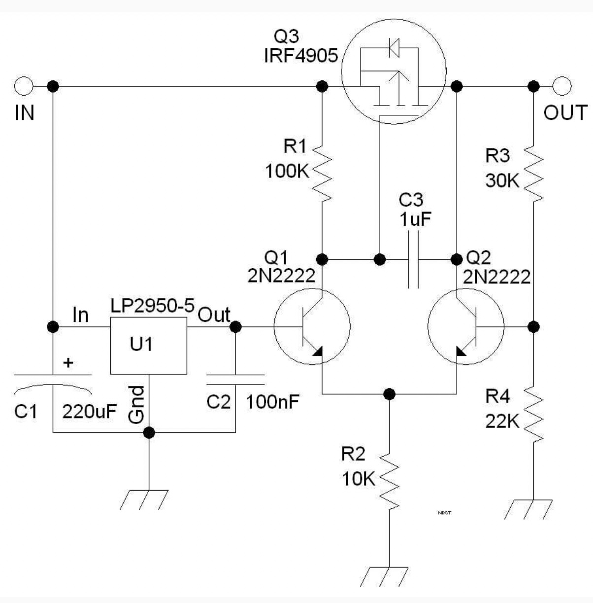
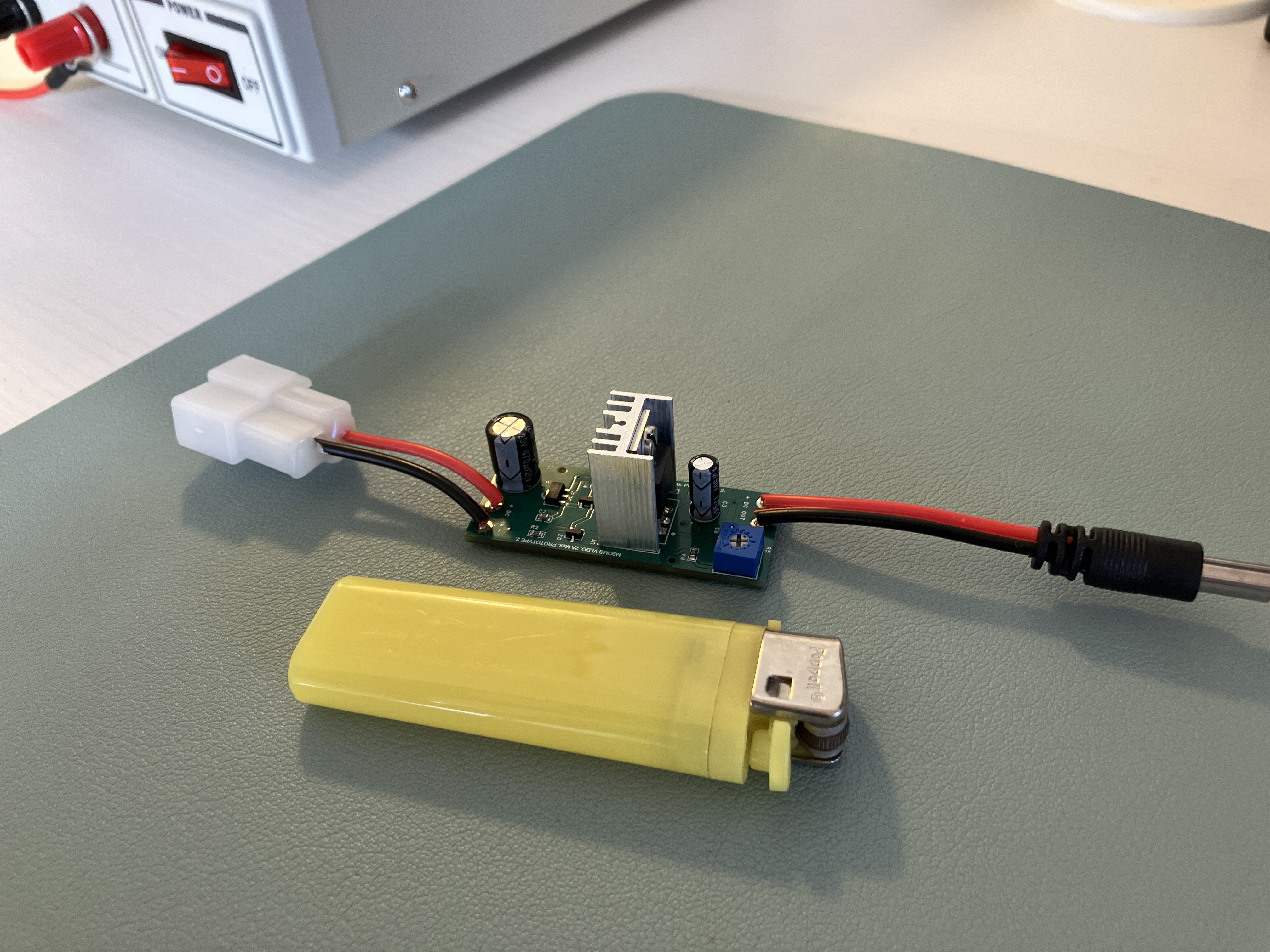
After seeing this VLDO circuit discussed on the QRP Labs forum, I decided to build one. This would allow me to use my LiFePo4 packs with the QMX if ever needed.
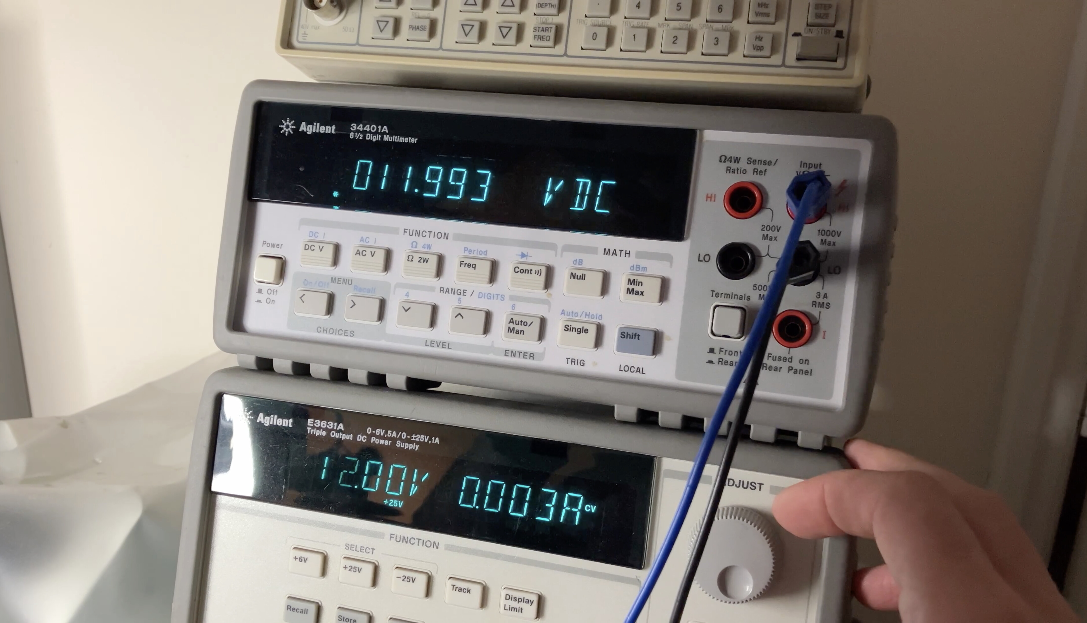
It gives a constant 12.0v output with only a few millivolt drop when the input drops to 12v https://groups.io/g/QRPLabs/topic/111670594#msg140561
I currently use a 3S Li-ion with a dropper diode that can be bypassed with a switch. It’s simple and it works well. This project was more motivated by desire to have play with KiCad for the PCB design. Plus I was stuck at home while we were having some work done
The circuit below is by ND6T, taken from the discussion referenced above, which itself is a variation of a design by G4COL
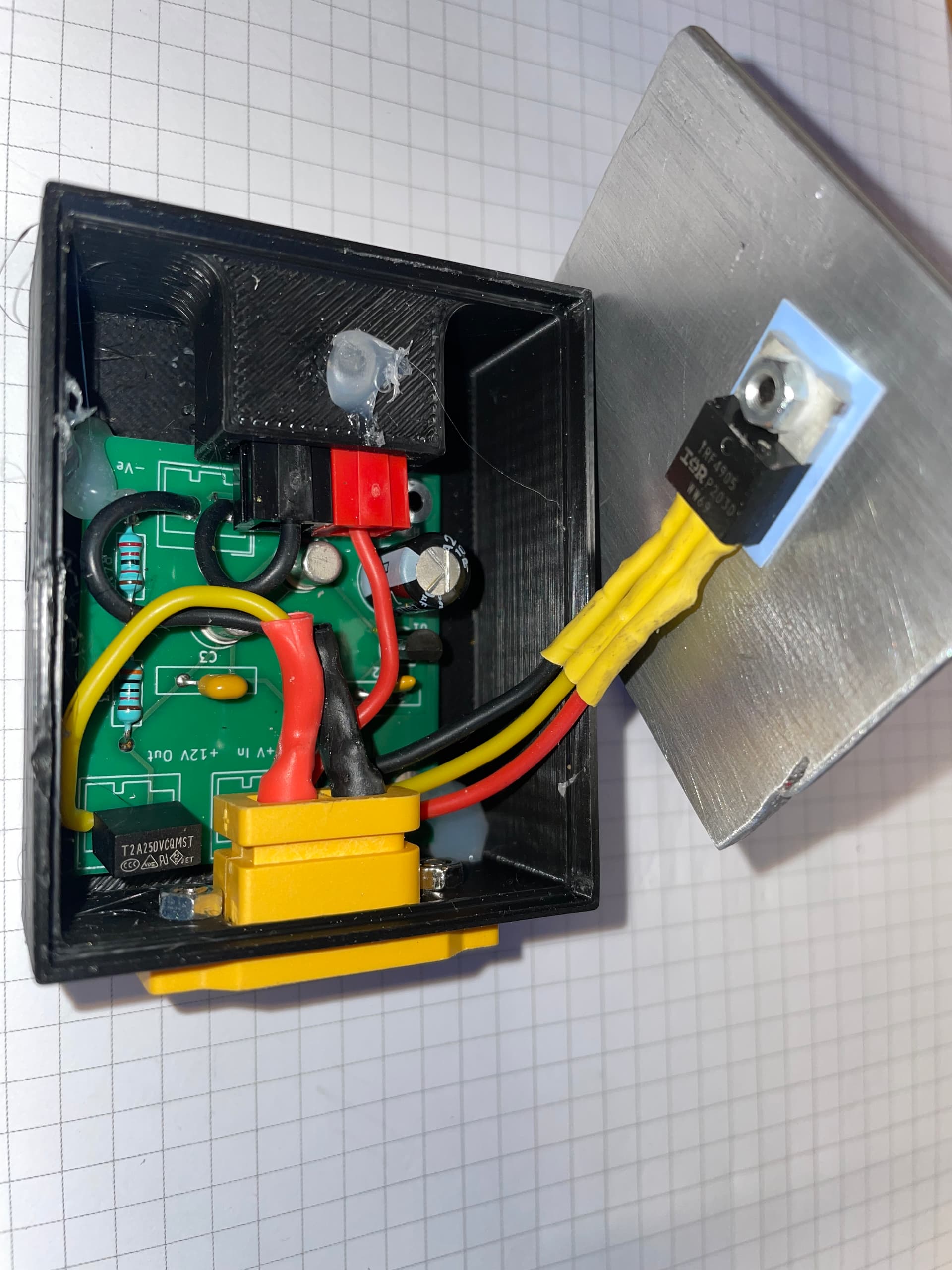
The heat sink was always going to the challenge. I had a play with some smaller heat sinks, but ended with a piece of 3mm thick aluminium, 50x60mm to give the desired cooling. When I tested this at constant 1.2 amps load, at 14.6 volts input, for 10 minutes, the max temperature was 34 deg c in a 19.5 deg c room.
Another note, I would recommend using 1% resistors for the potential divider R3 and R4, if you want exactly 12.0 volts out.
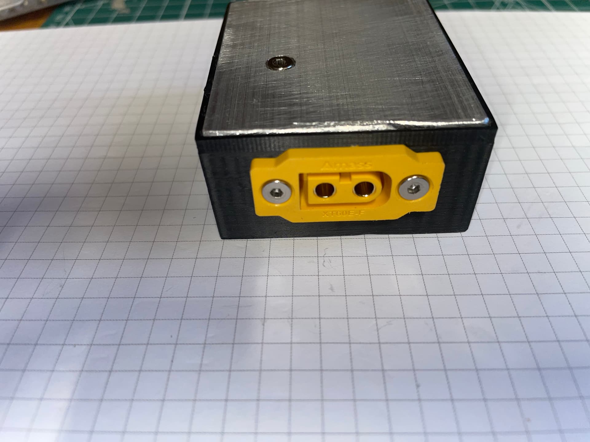
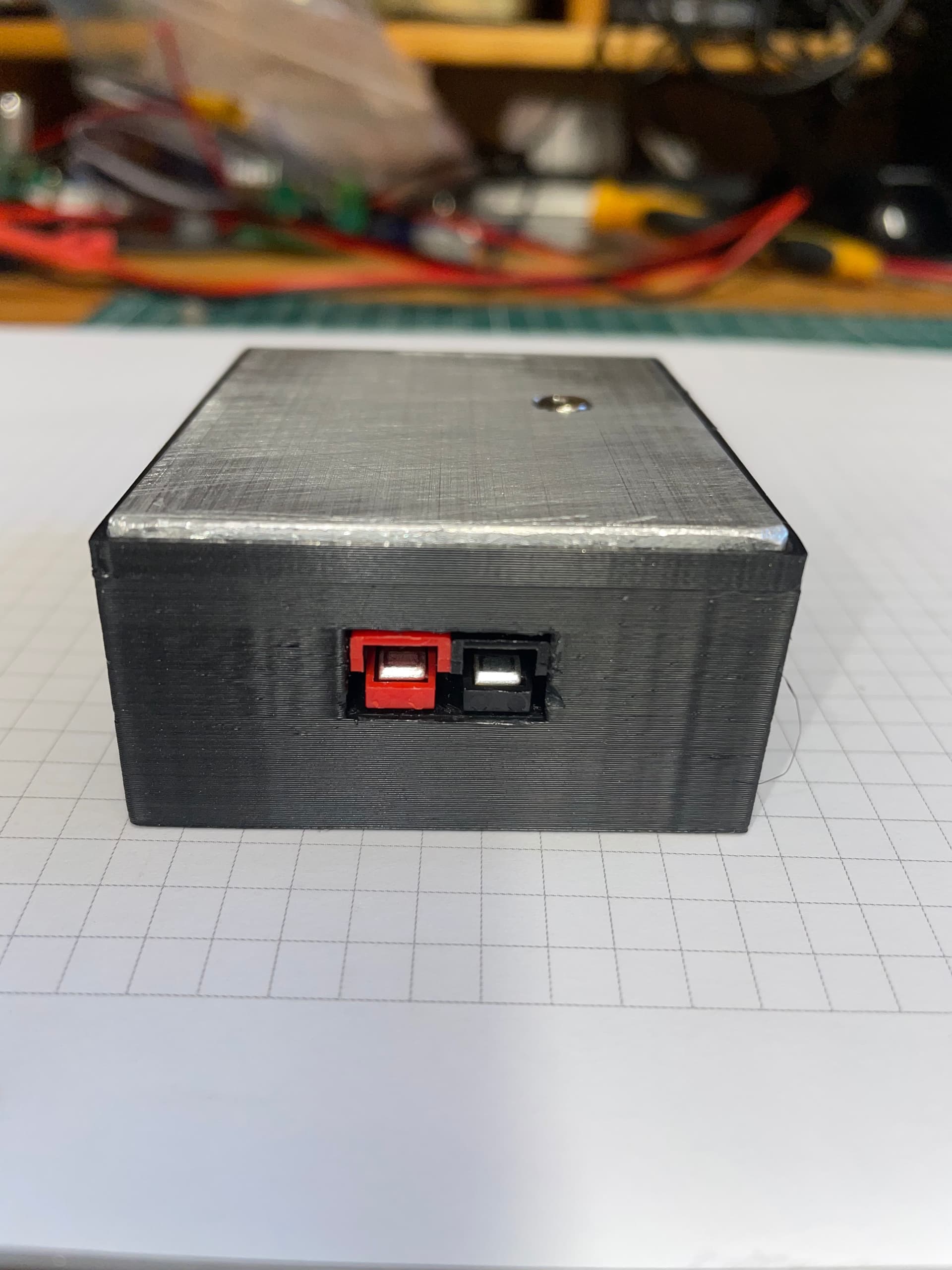
My choice of connectors is because all of my radio gear uses Anderson Power Poles except for the QMX. For the QMX I use XT60 connectors to avoid accidentally connecting it to a LiFePo4 pack.
I’ve done something similar, but I was obsessed with size. Lots of fun to get stuck into.
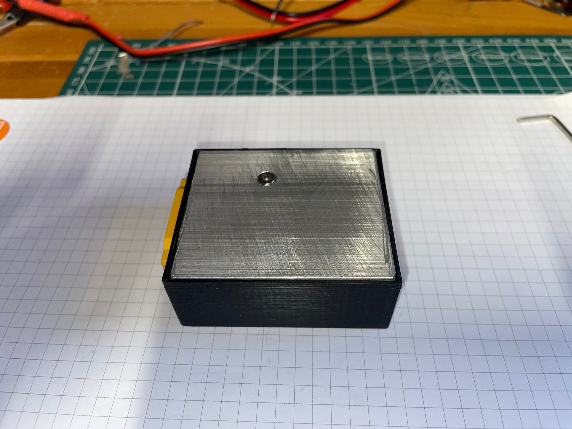
It works very well, but I’m undecided on the case - yours looks great! Alu lid is a very nice solution to keep it water resistant.
I’ve found the little heat sink on these boards are absolutely fine for SSB (on a 12v build) using my home QTH 13.8vdc supply… not tried digital modes though.
I went for a trim pot to get the voltage down to exactly 12.00… but in reality, I found that 11.95v worked better with the built-in voltage protection on the QMX (it’ll cut off at 12.01v, so a bit of wiggle room is good). I like to leave the voltage protection on just in case of any sort of failure.
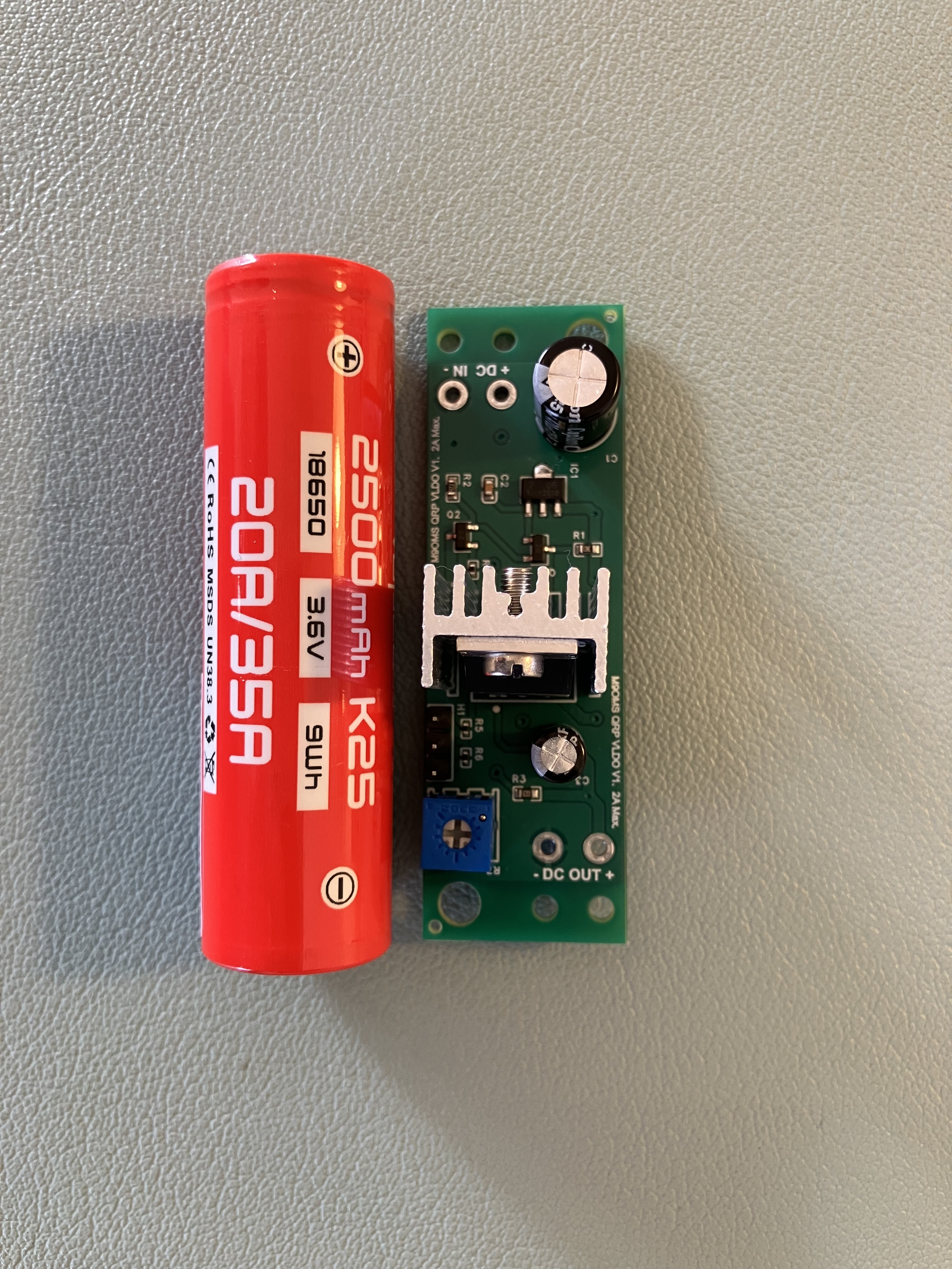
Then I went down the rabbit hole of adding voltage selection pins (in case someone with a 9v build finds it useful). I figured I’d get the board to roughly fit the profile of an 18650 cell in case someone wanted to build their own pack and fit it in there. They’re arriving in a week or so.
Here’s what I’ve been using/testing - works fine with my 3s LiPo and 13.8v power supply. BUT it makes my power connectors look rather large, so I’ll decide on something else to keep it all bijoux:
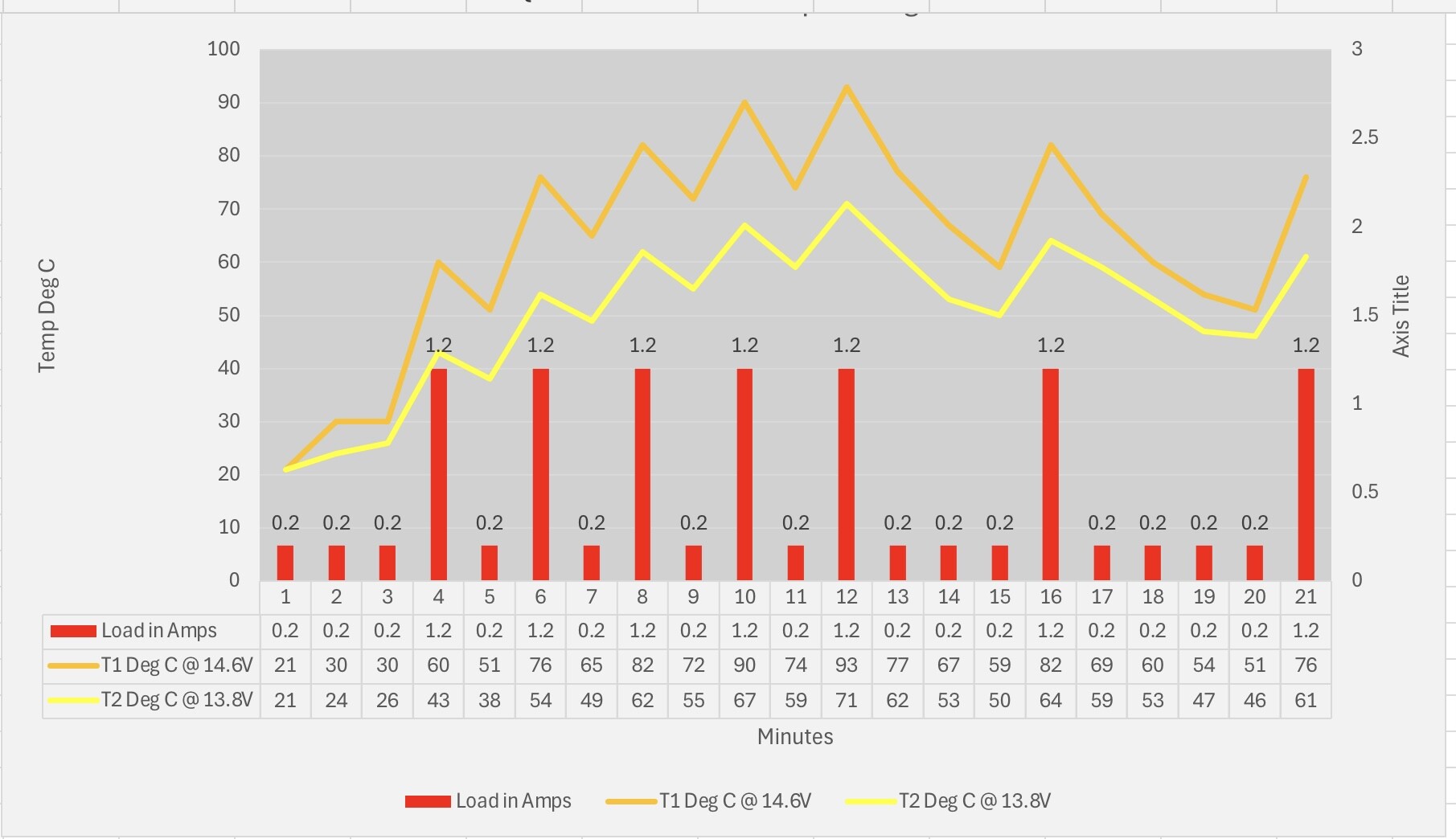
I did initially build it on strip board to test heat sinks. In testing a small heatsink, and cycling between 1.2 amps and 0.2amps at 14.6V, I was getting temperatures of around 80c. Graphs for the small heatsink test below.
I was attempting to simulate a worse case FT8 scenario. There was a quite a difference temperature wise, between 14.6V and 13.8V. I also added a 2amp slow blow PCB fuse on the output, as having no integral protection didn’t sit well with me.
Talking of rabbit holes, my case just kept getting bigger until I got heatsink I was happy with
These devices are excellent for small differences in voltage… after that, the thermal management becomes important.
Perfect for a wider range of input voltages.
Also, through-hole components are excellent for reducing the number of traces.
I hacked one board, and wired the mosfet externally (like you) to play with mounting it in a Smint tin (M&S no longer sell the larger pack of ‘curiously strong mints’, which were effectively Altoids).
But I then discovered that M&S sell ‘curiously strong mints’ in 18g tins. (tiny little things!)… so now the challenge is to get it under 10mm deep.
Rather than getting a nylon case 3d printed, I find myself obsessed with tins.
I have some 20x65mm boards arriving next week (the type with selectable voltage). To get it that small, most components are SMD - so they’re fully assembled.
@MW0PDV‘s board would be fun for self-assembly. Any plans for that Paul?
I’ve been following this thread with interest and also wondering what is wrong with just plugging in a 3S Li-Po or Li-ion? Diodes and additional boards add additional connections and more circuitry to go wrong in the field.
I have to admit I thought the same… my Lipo4 3s fully charged are initially 4.2v per cell. So the initial voltage is 12.6v. This drops quickly. Would the radio not handle that? I could set my charger just to go up to 12v though.
I am still waiting for my QMX, the wait is killing me!