That’s what I do, I don’t see a downside unless you really need every last mWH of stored energy.
Nice project though, and it might avoid problems if you have several batteries used for different purposes etc.
That’s what I do, I don’t see a downside unless you really need every last mWH of stored energy.
Nice project though, and it might avoid problems if you have several batteries used for different purposes etc.
What I use:
The 12v version of this (seems to be OOS at the moment):
https://www.amazon.co.uk/dp/B0DKY1S76D
Works great. ![]()
I routinely use a 3S LiPO fully charged. Never had a problem. Although many report having a problem. So, I think it comes down to your tolerance for risk.
73, Jared, N7MAW
The problem Fraser is the Class E PA design which results in high voltages in a energy-storage inductor. There is no problem when used at 12V and a good load match. But as the match gets worse the voltages can rise. With a high enough supply voltage and and bad enough match the voltages can exceed the maximum drain - source voltage for the BS170 PA FETs. Do that enough and it’s “Goodnight Vienna”. There are lots of protections built into the software of the radio that minimises these problems. But the essential takeaway is 12V means 12V and keep the SWR low.
With that in mind you need to do 2 things… keep the voltage to 12V and SWR as low as possible. The problem with SWR is as we all have experienced is that antennas randomly rigged in the field can often have variable matches, even dipoles and especially the xOTA hams favourite, the EFHW. You need to test the match at lower power and check everything is OK before letting rip.
As the 12V design wants 12V and a 3S LiPo is 12.6V dropping quite quickly as it is used, it feels OK to use such a battery as is. And if the match is good and everything in the universe aligns, you’ll never have an issue and will wonder why there is so much noise about this. But in this case the issue is fixed simply by inserting a small-ish power diode in series with the supply.
A IN5403 is cheap and readily available and more than man enough for the job. It’s a 3A diode and when used with a QMX and it’s max current load of around 1A, the voltage drop will be 0.6-0.7V, that immediately fixes the voltage issue. After sometime the battery voltage will fall below 12V and the supply will be 11.3V or so and it would be possible to remove the diode. A shorting switch would allow the dropper diode to be switched out. I don’t know about the QMX but the QCX has a voltage display and as an op you can use that to tell when you can switch the diode out. The only worry would be to remember to start with the diode in circuit. Solved by having a “preflight checklist” like pilots run through before they take off so the they don’t fail to take off and kill themselves ![]() There’s an SWR meter and SWR protection in the QMX and if you have kept the voltage in range, you can allow that to work as you check the match.
There’s an SWR meter and SWR protection in the QMX and if you have kept the voltage in range, you can allow that to work as you check the match.
The biggest issue is a failure by many to understand that whilst there will be a power drop running a 12V set at 11.3V, the actual power drop is going to be completely insignificant in real terms. There is data on the QRP labs mailing lists showing the marginal drop in output power vs. supply voltage and ISTR the power drop in this case 12V->11.3V is two thirds of five eighths of naff all. Maybe, just maybe if you run FT8 you may a slight change in the measured strength but I’d doubt CW/SSB users would notice any change should you switch between 12 and 11.3V.
I can understand people thinking that using a diode Vf to lose the voltages as being wasteful and that a SMPS is better. Well an SMPS will be more efficient and thanks to cheap manufacturing in China, you buy them for not a lot. But I bet I can buy a lot of 1N5403s for the cost of one SMPS. And it’s guaranteed not to produce RF hash ![]()
I was always brought up with the fact that a good engineer achieves success when only spending ten bob on the problem when his competitors spend five pounds. Which is why in the case of a radio drawing around 1A, a 3A diode in the supply is a fine engineering fix ![]()
Does that mean that people should not use buck converters or in this case a nice system to regulate the supply voltage by losing the excess volts across a FET? Absolutely not. It used to say on UK licences “self training in wireless telegraphy” and so making PCBs using cheap design services, building circuits and solving heat problems to run your radio seems like a fine example of that licence statement. But many years of engineering says a power diode is the simplest fix.
The USB PD spec power supplies can be made to provide a range of voltages by using the correct cables to select the voltage. But people should be aware the 12V output has been dropped from the spec for sometime now and so any pack that provides 12V is using the old obsolete chips. When such a PD pack fails a few years down the line you may find it then impossible to replace. Likewise some appear RF noise free. I do remember buying 3 boost converters to give 13.8V from 11.1V to power my 13cm transverter which needs 13.8V for full power. Mine is noise free, the one I sent to Barry GM4TOE is noise free and Jack GM4COX’s is somekind of electronic countermeasures noise source… all three are from the same batch/vendor. Go figure.
My $0.02c on the subject. You’re welcome to disagree with me but that doesn’t make you right ![]()
Well with PCB way it costs the same for 1 PCB or 10, so I have 9 spare ![]() . If anybody wants one I am happy to post one to you.
. If anybody wants one I am happy to post one to you.
Nothing wrong with 3 Li-ion and dropper diode. As is said in my post that’s what I use. I may never use the VLDO that I have built, but now I have started to learn KiCad PCB design software. And it stopped me going stir crazy whilst I was stuck at home having work done. ![]()
Good point, but luckily the new ones often support PD 3.x PPS (Programmable Power Supply), allowing the sink to request any particular voltage in 20 mV steps within the range supported by the source. So with a modern power bank and a suitable PD trigger cable, one can still get 12.00 V or whatever ![]()
Andy has a good response (above).
What I’d add: Not everyone will use a small capacity (say 1Ah) 3s LiPo, so it may take longer for that voltage to drop. Obviously as SOTA operators, we may go small and light, but not everyone else will.
Let’s not forget the QMX+ (many used at the home QTH, as well as mobile/portable). Some operators simply want to use ‘stock’ ham radio PSUs, or indeed “12v” car batteries.
So a solution that can work in the field, car, or at home might be useful to someone.
I’ve enabled the voltage protection my QMX not to allow a voltage of more than 12.0v (that’s probably the source of confusion). So >12.0v, the radio will not Tx at all.
I’ve also enabled the SWR protection: >2, no Tx.
My beautiful baby will only get the best treatment: dry weather, regular cleaning/polishing and a good healthy diet of organic electrons. I still need to buy a helmet for it.
I did exactly that and it’s been fine most of the time.
On one activation, it set off the voltage protection because the voltage crept up (that can happen)… but it wasn’t a problem at all. I just couldn’t find the **** menu option to disable it. ![]() I found it eventually.
I found it eventually.
Never say never. Heck, batteries available to purchase might change. The goldilocks 3s LiPo might not always be as popular as they are now. You’ve got a nice piece of kit that gives you voltage flexibility.
A prime example of the KISS principal which would certainly float my boat if I were a QMX. owner. ![]()
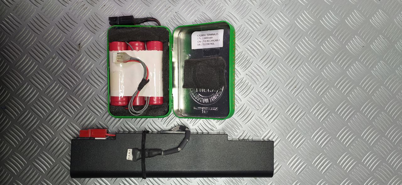
I “fixed” this problem by buying a DIY power bank where I can replace the battery cells when they fail. Just assuming the chip lasts longer than the batteries…
![]()
I would also like to receive on of the boards! In turn I would volunteer to design and print an enclosure.
73 Heinz
Hi everyone.
I’ve been using the same system as @HB9EKO Jens for a while now.
I bought these 12V triggers:
I built the cables:
Or this one:
I have a lightweight USB-PD battery (homemade).
And another heavier commercial battery that allows me to perform many operations without needing to recharge.
https://www.amazon.es/dp/B0C3GTMX5M?ref=ppx_yo2ov_dt_b_fed_asin_title
The procedure: I connect the cable to the battery. The trigger requires 12V; a small blue LED indicates that 12V is available. Then I connect the QMX. It has never failed me.
None of these batteries interfere with my receiver. Carrying it in my backpack gives me peace of mind. I always have enough battery power for everything. In case of need or emergency, it allows me to charge my phone, GPS, walkie-talkie, etc., all at the same time!
Good luck!
73 de Dani EA5M.
I am doing the opposite. I have 3s1p and 3s2p LiIon with shottky diode on the cable to qmx or ft817. If I need to recharge my phone or something I am using stepdown 12V to 5V usb converter
Yes. Damir @9A3IV. I’ve also used that system (3s1p and 3s2p) for many years.
But I can assure you that once you use the USB-PD system, you’ll like it better.
73 de Dani EA5M.
I have been using a TPS61088 module from a popular online store (name starting with Ali). It is a sync boost converter that can deliver 12 V and sufficient current. Very satisfied with the performance.
If you tune around, there are tones at some harmonic frequency, but for mine they are conveniently out of band.
I feed it with 2-10 18650 batteries connected in parallel in order to reduce the current draw per battery (which is expected to result in more available energy according to some discharge graphs I found on the internet).
An added advantage is that no BMS is needed. The module by itself will not discharge the batteries lower than a safe voltage. Batteries with different capacities (as they unfortunately come from the online store) can be connected in parallel and so discharged. A nasty failure mode of series connected packs where one battery gets discharged too low is eliminated.
An additional benefit (not related to QMX) is that the module can also be set to 9 Volts (or any other voltage, but there is a jumper for 9V), which is a convenient supply voltage for the FT 817. Higher voltage would provide only limited additional TX power (0.5 to 1 Watt, depending on the band) and no benefit on receive.
See Yaesu FT-817 Portable QRP MF/HF/VHF/UHF Transceiver for details (look for the “FT-817 Output Power Variation with Supply Voltage Graph”). I did some measurements a while ago which were inline with these results.
73, LZ1EEA/P
Kiril
It looks like boards are good. ![]()
See KC7XE’s post on Groups io: https://groups.io/g/QRPLabs/topic/omar_m9oms_very_low_voltage/116389606
I’ll work on getting it better at inputs below 9VDC, but in practice most people will be using a 3s LiPo for their rigs. I certainly wouldn’t discharge my battery down to that level. Current limiting would be better to prioritise.
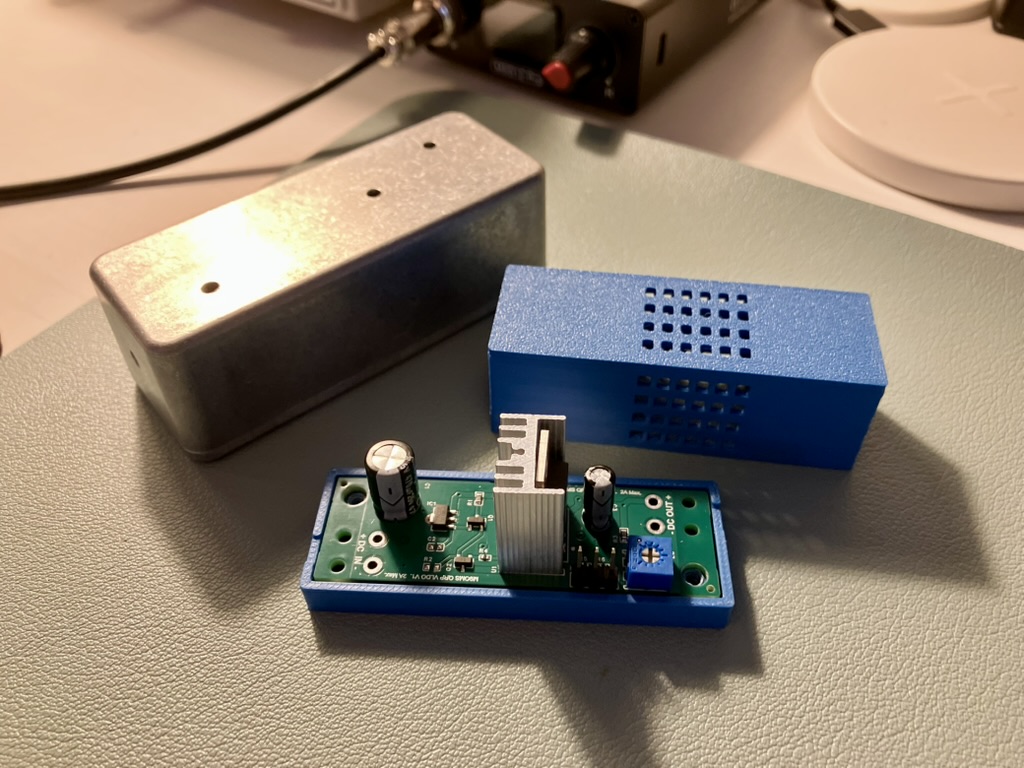
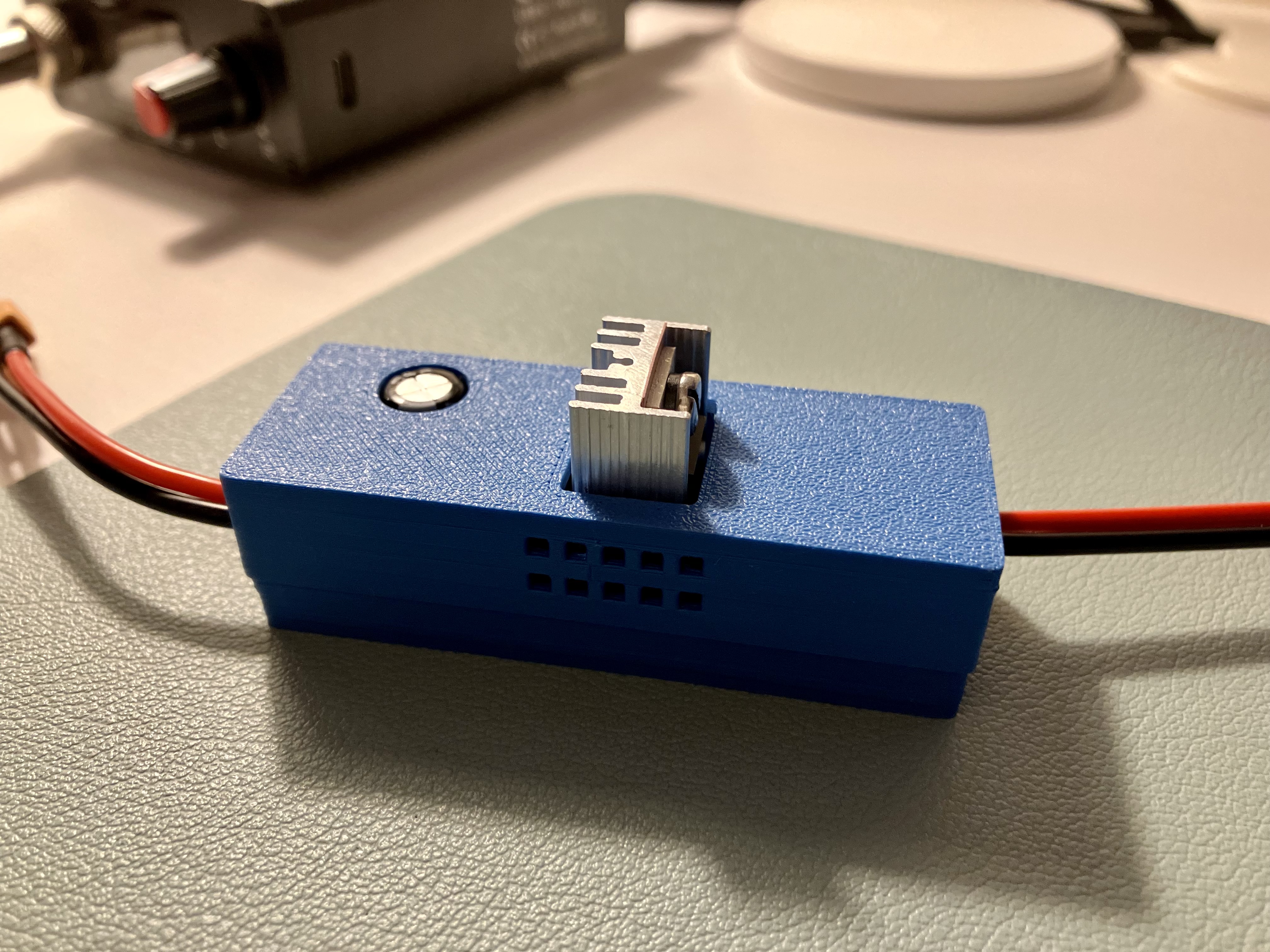
Here’s a 3D printed case next to my aluminium enclosure. Printing your own is certainly smaller & lighter. But by going down the ‘closed top’ route, one needs to print it in Nylon, limiting voltage drop & current draw to sensible levels (the heat sink is only good for dissipating 3W at a 50% duty cycle).
@OE5EEP - I’ve settled on this for the time being (yes, I’ve been playing limbo HI).
The mosfet is isolated from the heat sink & M3 screw. The tab is exposed (which doesn’t bother me) but it’s something to consider for smoke-proofing I suppose. ![]()
I’ll PM you a link to the files.
EDIT: See comments further down below - audio feedback seems to be a problem. It doesn’t seem to be radiated. To me, it seems this combination possibly doesn’t handle transients well, perhaps affecting the audio.
Agreed. I struggled to find one sold by domestic UK retailers…
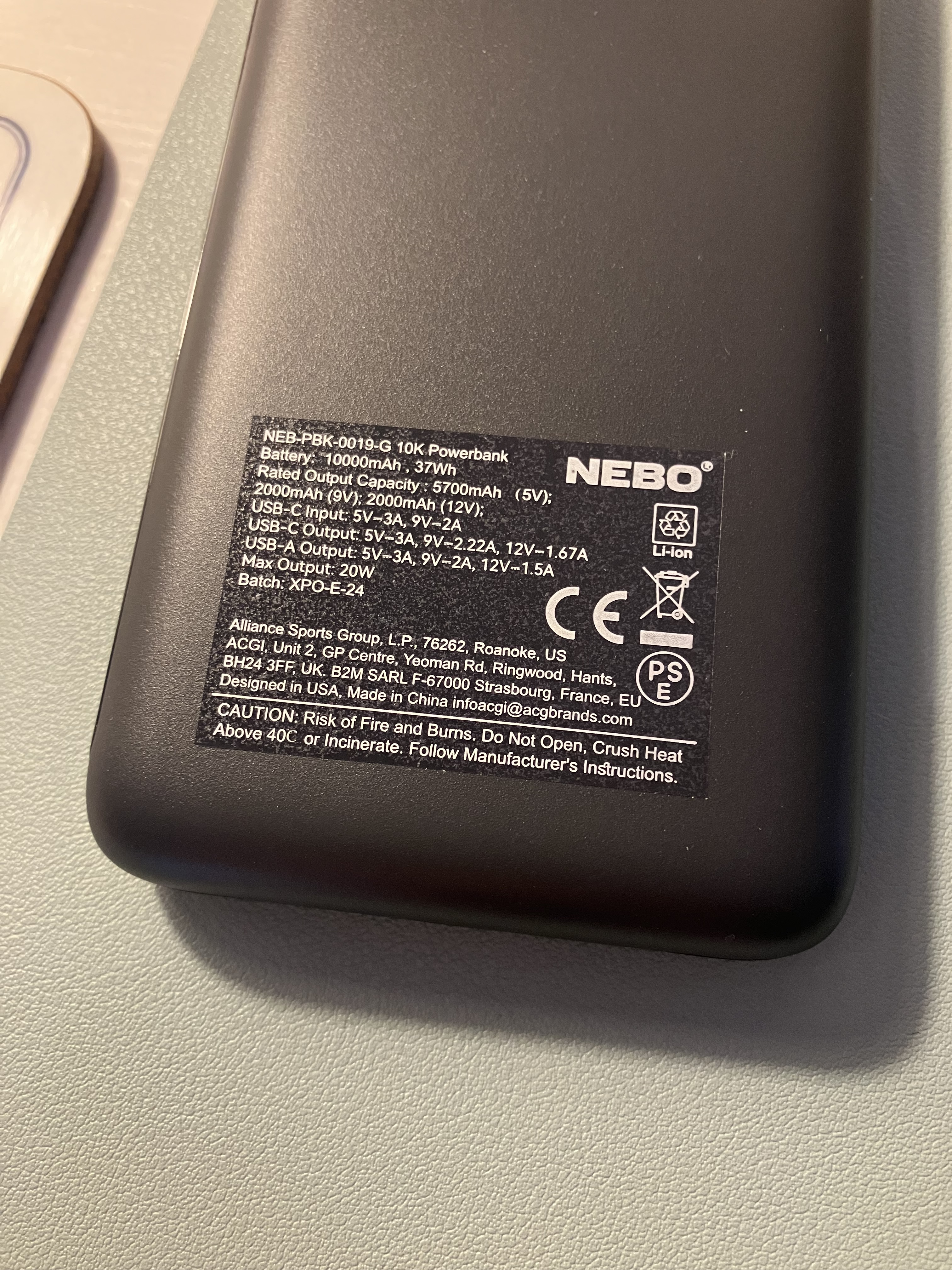
But I eventually found one that supports USB-PD 12V for both USB-A and USB-C: the ‘Nebo 10k’:
https://www.screwfix.com/p/nebo-37wh-power-bank-black/656CY
Way bulkier and heavier than my VLDO + LiPo setup, but as I’m travelling overseas it will offer some benefit (though off-putting for 6 point summits HI):
1- I only need to take one AC charger with me.
2- It can charge my phone, tablet, watch and inReach.
3- It can charge my FT-65 (via the PD trigger cable + cradle).
4- It can power my QMX (via the PD trigger cable).
5- Airport security are used to seeing power banks.
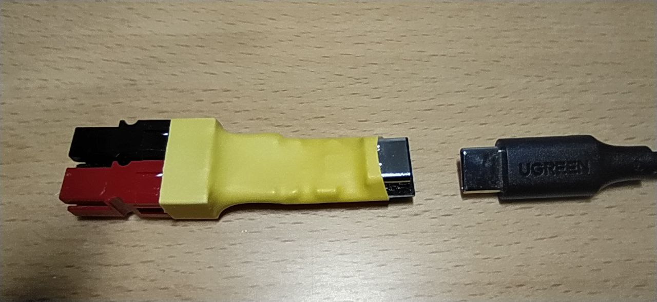
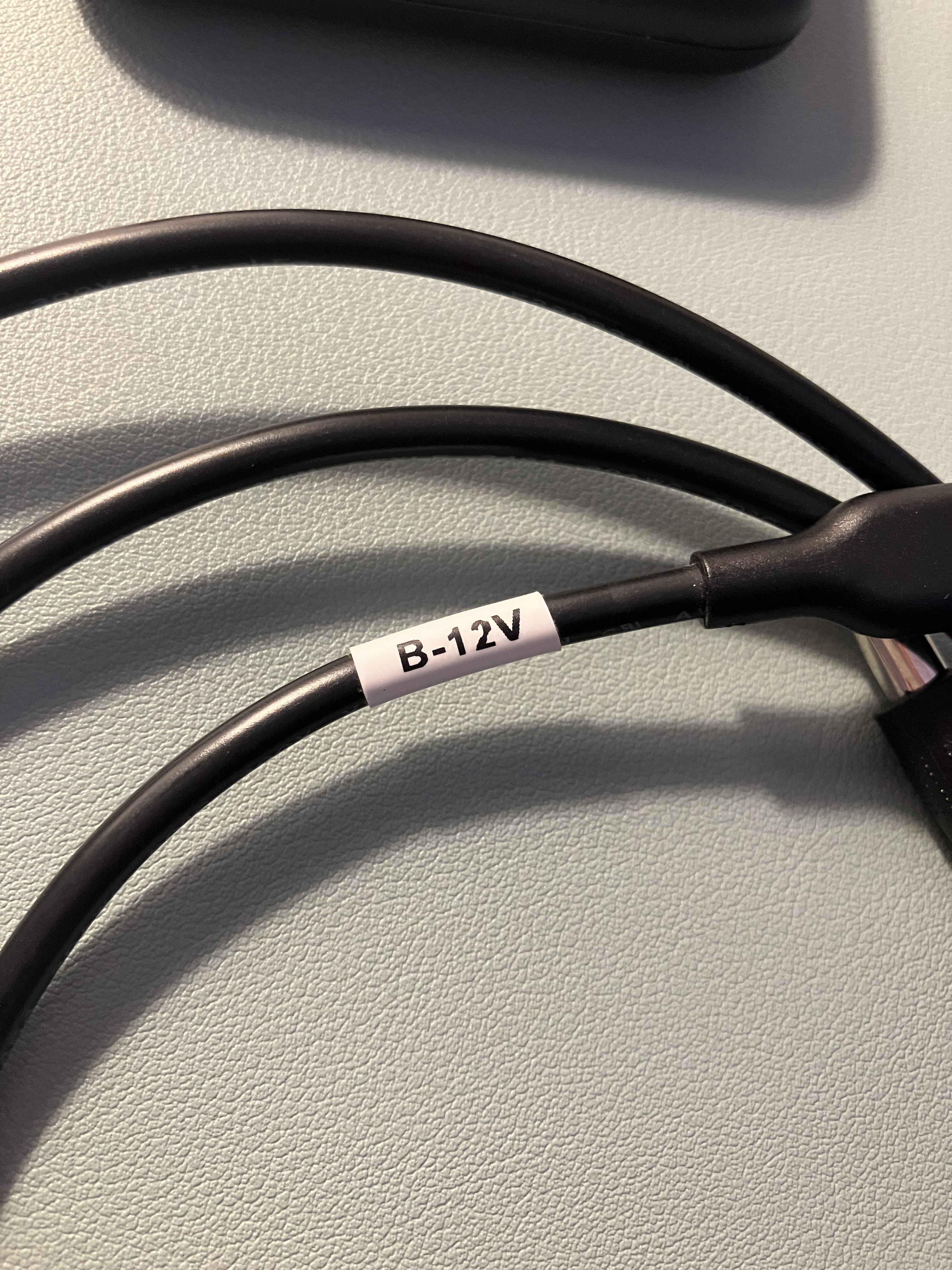
For the PD trigger cable, I bought this (12v, 5521 barrel):
https://www.amazon.co.uk/DSD-TECH-MagicConn-Power-Cable-12V/dp/B0C58PXB4H?ref_=ast_sto_dp&th=1
One bad review. Unclear, but it appears someone was using this device backwards (ie to supply 12V out through the USB-C connector?!)
Behaves as it should (starting at 5V during the brief negotiation, then climbing to 12V).
With no load, I get 12.04V out of the combo (an idling QMX ‘sees’ 12.0V), and I get a 0.15V drop when keyed down (the QMX sees a 0.5V drop).
The setup seems OK (as far as a basic multimeter can tell). ![]()
The power bank wakes up when the cable is plugged in, and after 15 minutes with nothing connected to the barrel - it’s still on. Extended periods of idling (RX or finding a free frequency) should be fine.
No noise issues? or not tried it in anger yet?