Whilst chasing John @G0MHF earlier on 2m FM, I noticed my FT-818 and FT-2980 were showing 18v on the display… rather unusual, so I checked the output of the Watson W-25AM power supply I use in the shack and sure enough, my multimeter also shows an output of around 18v when I transmit on either radio.
It seems stable enough with no current draw, i.e. sticking to 13.8v, but any time I TX it goes well above 13.8v. It still supplies 10+ amps for the FT-2980 on TX, but I’ve disconnected the rigs for now.
Has anyone else come across this before? Google and Reflector searches come back with faults where the voltage goes low, but I can’t see much about it going high. Maybe I’m special ha ha!
Is it time to replace this? I think I paid about £50 for it ten years ago, so it’s done fairly well really.
Thanks & 73, Simon (now chasing from home with battery power only).
You may have a lot of RF in the shack. First thing to check is the aerial swr using a battery for the rig Power Source and then the feeder screen DC connection at both ends of the cable.
18V must be close to wrecking the radio, including the PA stage on over voltage.
Another test would be to put a resistive load on the PSU - a car headlamp bulb, or whatever you have that would draw a couple of amps at 12V. If that is stable, it supports David’s RF suggestion…
Hi Simon, thanks for the call earlier today & I’m glad the Watson didn’t blow up your 818 in the process. Bit of a mystery this, I’ve had the opposite with low voltage on an old Maplin power supply.
I hope the hive mind can come up with a solution. Btw, where was your cover photo taken? It looks rather high altitude. 73 John.
Hi Simon,
If you are confident in working on equipment, I’d disconnect everything from the PSU (of course). Leave it a couple of hours to discharge and then take the casing off and see if you can see any burnt parts - I’m thinking of a resistor in the regulator circuit that could be damaged and as it heats up with more current draw the regulator is somehow being told to increase the voltage.
OK, if this is a switched-mode rather than a linear unit, that might not make sense but I would still start with a visual check and if you see what looks like a burnt component, replace it and try again, into a 12v load, like a car light bulb as has already been suggested.
Yes, I think I was lucky as the radios seem OK. Nothing antenna-wise has changed for two+ years, and all is fine on battery. i.e. VSWR is fine on the 2m co-linear and on my HF fan dipole.
I just connected a H1 bulb, which glowed extremely brightly for 2 seconds before blowing. I have an LED voltmeter attached, which now shows 23.8v output. My multimeter shows the same. Perfect if anyone needs a 24v PSU I suppose!
The picture is of me on Pigne d’Arolla, HB/VS-052. We climbed that on a Jagged Globe Alpinism course. Unfortunately I wasn’t in a position to activate it back then, but it’s a lovely summit to climb with fantastic views across to some of the more well known mountains in the range.
This has no overvoltage protection at all. I wouldn’t use one. That doesn’t solve your problem now. However, until you find the cause, DO NOT CONNECT RADIOS to it.
Most likely, as explained, RF feedback is screwing with the regulator. If this has just starting happening now then something has changed with the antenna. Prove it’s RF feedback by loading the PSU with some loads like car headlamp bulbs etc. If the voltage stays fixed then it is RF affecting the regulator. If the voltage still goes up you need to look further. The circuit is available online.
Once fixed/cured make an overvoltage trip you can add to the PSU output between the PSU and your valuable radios.
EDIT… ah it’s now always 24V… either the regulator is giving too much or Q2 has failed driving all the TIP2055s (Q3/Q4/Q5) on hard or one of them is now Collector Emitter short.
You were lucky, Simon. I had a PSU go high voltage and it blew out some components in my FT857, fortunately it was repairable. I suggest that if you repair the PSU you add a crowbar overvoltage protection circuit, a circuit that shorts out the input and blows a fuse if the voltage goes too high.
I would agree with MM0FMF, check the power transistors.
Based on an ep625 PSU I repaired which had the same over voltage problem. I would check all the power transistors, they were 2N3055 in the ep625 PSU but most of the linear PSUs of that vintage used a similar arrangement.
This one uses plastic TIP-2055, plastic in TO-3P packages. It has 3 in parallel which seems a bit lacking for 25A PSU. I’d have expected 4. A few data sheets show the device can dissipate 90W (if you get the heatsinking correct).
As the measured O/P voltage is now 23.8, that will be the raw unregulated voltage which is a bit high. Output is 13.8 so we loose 10V across the device. Current is 25A so dissipation is 10*25 = 250W. Shared over 3 devices is 83W. That’s close to the max continuous dissipation. OK this is a “cost engineered” PSU so the transformer will be barely big enough and the unregulated voltage will be up and down like a whore’s drawers as the current drawn changes but it’s expecting that the fan and heatsink are doing their job very well if you run this at load for any length of time.
It seems like it’s right on the edge for a PSU rated at 25A continuous.
Thanks Brian, I have found a suitable crowbar circuit, which is now a priority on my to-do list! Very lucky. Just tested the FT-2980 on battery and it’s OK - I worked @M0WBG Neil on GW/NW-044. Just need to test the FT-818 and amplifier next
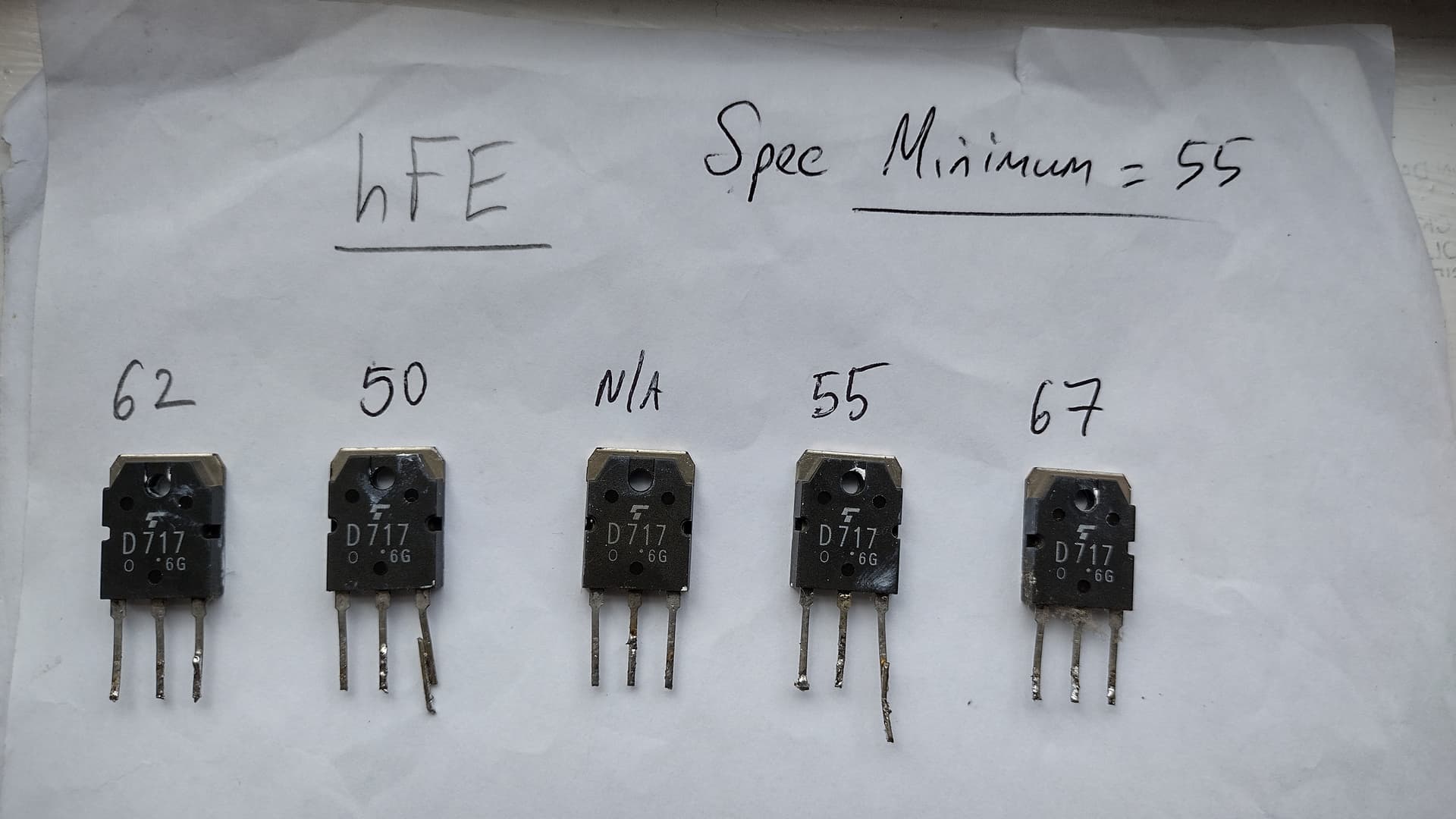
I have 5x 2SD717 transistors in mine. I have tested their hFE with reference to the spec sheet and one of them is definitely kaput. Not sure how closely matched the hFE should be - picture attached. Should these be replaced as a set do you think?
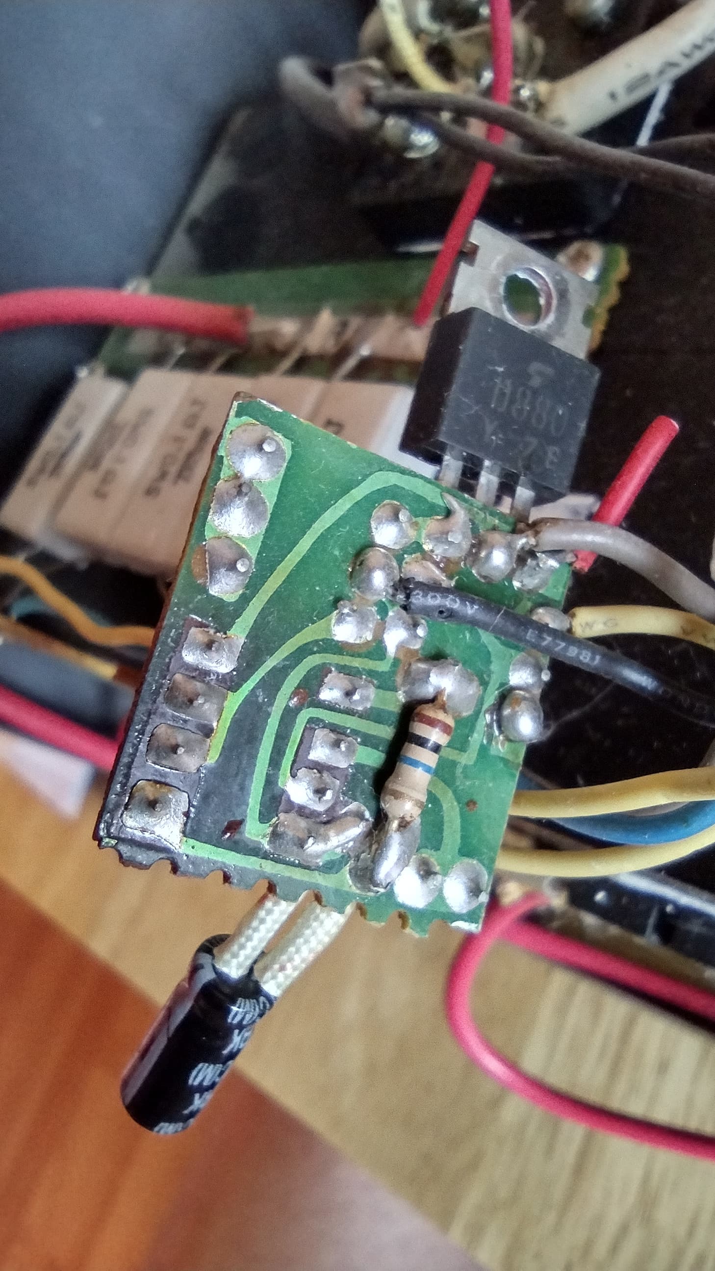
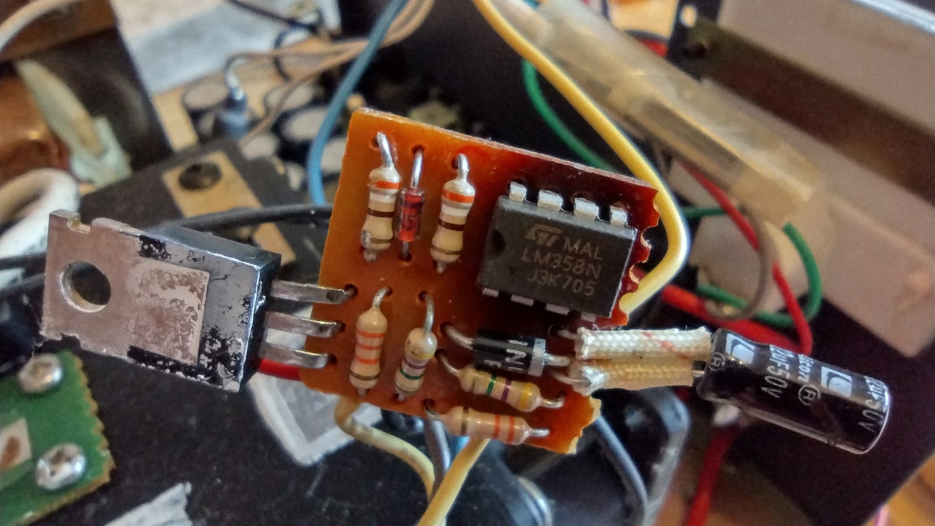
I’ve also found something that looks cooked following Ed’s advice @DD5LP - see circuit board picture with an LM358N. I need to remove the two 2SD880 transistors next and test them.
In the meantime, thanks to @G3CWI Richard’s awesome flea market, I’ve found someone selling a 10a power supply, which will get me back on air (as long as I don’t use full power on the FT-2980. Off to collect that tonight as they live in my area.
5x 2SD717 ? 4x 2SD717 as the parallel pass transistors and 1x 2SD717 to drive them I wonder? Or 5 pass transistors and there’s something else driving them. Hard work finding a definitive circuit for this.
They don’t need to be matched that closely Simon because you have a very low value resistor in each emitter to balance the currents in each transistor. Oh my I’m getting old… I’m sure that is called emitter degeneration but it’s so very long since I did proper analog stuff it’s all got very hazy. It helps when all the devices are mounted on a common heatsink and are all at the same temperature.
It does look like there’s one been removed from the heatsink already.
Hmm, I noticed that too Andy, but it doesn’t look as though anything has ever been soldered onto the corresponding points for that 6th transistor.
I suspect someone has worked on this PSU since original build, because the fan has never worked through the original temp sensing circuit, it’s just been permanently wired on. The voltmeter doesn’t exist (just an empty space for it), hence not really noticing the fault until I saw the radios’ reported voltages fluctuating.
Pricing up repairs, 2x D880 would be £6. 5x D717 would be £27.70 and the LM358 is only £2. That’s assuming nothing else needs changing. I’m not convinced it’ll be cost-effective or worth the risk to repair, as these power supplies seem to sell on eBay for £35 - £50.
Does anyone want a free winter project…? Ideal if you have the parts in stock. All mine are with Dad on the Isle of Wight and I’d be surprised if I have these exact items.
HP HSTNS-PL18 psu from eBay for about £12.00 Change a few components and you get a 13.8V 50A PSU. We used one on VHF FD last year to power an IC7300 for 48hrs.
 & 73, Simon (now chasing from home with battery power only).