When enabling the 60-meter band loading coil, as Geoff did, the antenna is resonat on the 60-, 30-,17- and 11-meter band.
No resonance on the 12 meter band though, but a tuner can solve this mismatch for the transceiver.
Not optimal, because of lower impedance at the coupler at around 25MHz and a coax before the coupler increases the losses even more, but when conditions are good, it will work.
@Stephan,
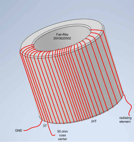
I’ve started to build an end fed as descibed in the .pdf, I ordered 10x of the Fair-rite 2643625002 toroids from Mouser, I ‘think’ I have wound it correctly, 3 turns on the primary and 24 on the secondary like this
(apologies for the drawing, I am away with work and my work laptop doesn’t have much drawing software on it).
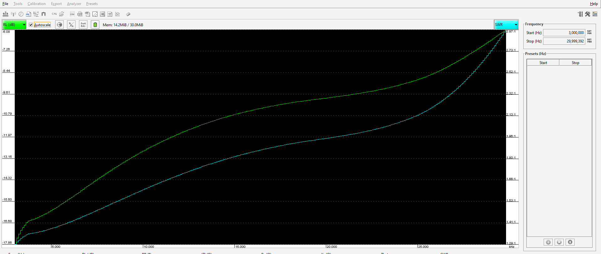
I have yet to try it on an actual radiator, but terminating it with fixed value non inductive resistors, and playing with the capacitor values, the best sweep I can achieve is this
That is with a 100pF cap across the primary and 3.3k terminating the secondary winding, the sweep with the ‘normal’ FT114-43 type bifilar wound primary transformer is much flatter than that, I wonder what your transformer alone swept like when terminated ?
When I am back at the weekend, i’ll string out 20m of wire and see what it looks like then.
My experience is that poor showing on higher bands is usually due to too long wires on primary side, too loose winding (low inductance). This would mean that if you squeeze turns very close and it is too bad its worth changing number of turns from 21/24:3 to 28/32:4. Also wind 10 turns and measure inductance to verify core AL value.
Thanks for asking, you showed me a weak point in my document!
I definitely have to clarify this step about making the turns/windings in the document.
If I counted it correctly in your drawing, it seems you did in total 27 turns, but they should be only 24, because the first 3 turns (of the primary) are part of the secondary winding, since it’s an autotransformer.
BTW: in case you create a new drawing, could I use it for the document? I think that would make things much clearer, but I’m terrible with drawings.
So you did an 1:81 impedance transformer (3:27) instead of a 1:64 (3:24), which according my experiments, works not that well on the higher bands, but is fine, or even better, on the low ones.
So the SWR curve with your 3.3k Ohm terminating resistor and 100pF primary shunt capacitor should get better, but the higher bands (especially 10m) will still be not that well matched. I also did these kind of lab measurements, but at the end of the day, what really counts, is the whole antenna system in the real environment.
As @SP9TKW said (if I understood him correctly), one can improve the matching of the higher bands by reducing the impedance transformer ratio (e.g. instead of 1:64 use 1:49) and/or reduce the primary impedance (e.g. 2 instead of 3 turns), but the price of the latter is reduced efficiency. Less efficiency may mask a bad SWR but makes the operator happier .
No problem, one I get the transformer correct, I will re-draw it using something better than Paint, you are welcome to use it in your document.
I had 3 turns then 24 turns, because I counted the turns from the picture in your document
There seem to be 3 turns, then 24 turns, making 27 in total.When I am back home on Friday, i’ll take a few turns off and see what effect that has on the higher frequency end.
This picture origins from Figure 3, which is the test coupler allowing to switch the transformer ratios (1:36, 1:49, 1:64 and 1:81), as well as the primary shunt capacitor, and is intended for field measurements (see chapter 11 Test Coupler VSWR Measurements in the Field).
Since it has a max. transformer ratio of 1:81, you counted these turns. When you look at the picture you posted, there is a tap before, with 3 turns less. This is the one with the 1:64 ratio, consisting of total 24 turns.
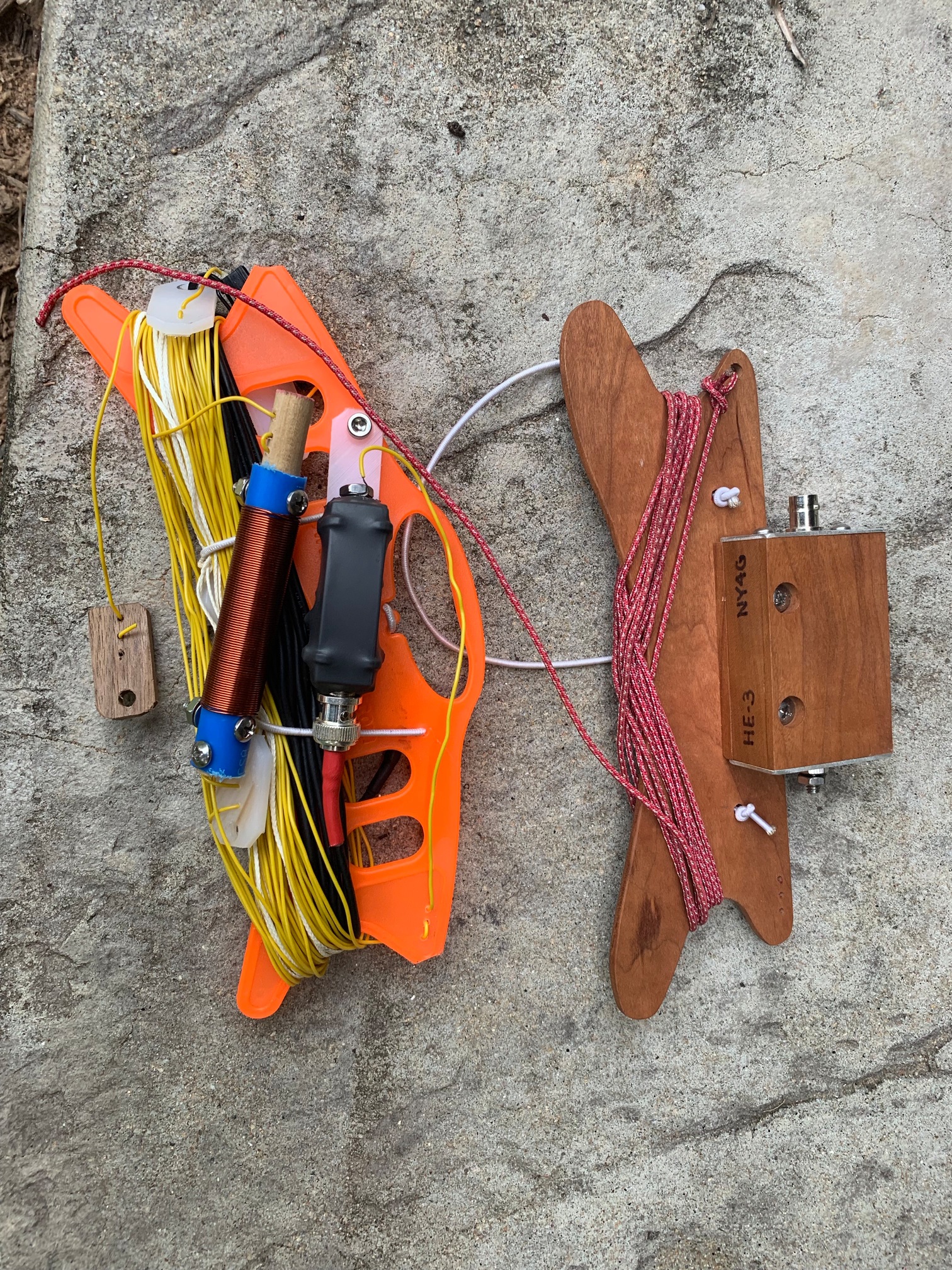
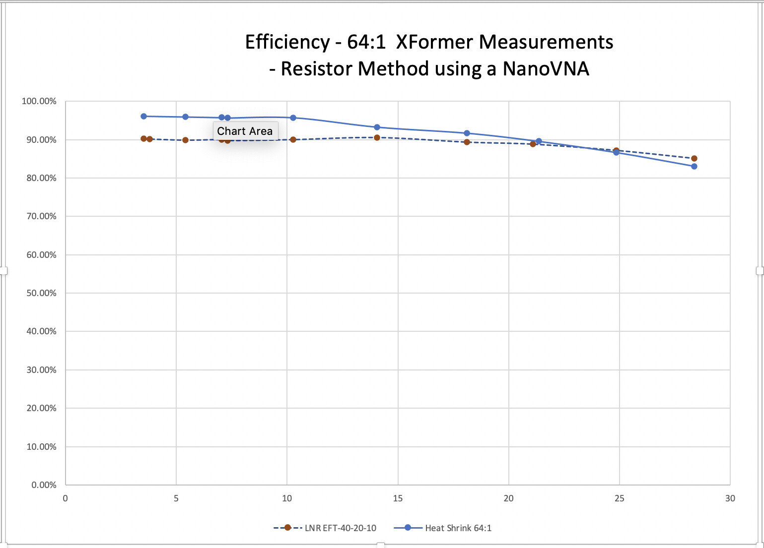
Your article inspired me to build a variation on the same theme. I had been building with the same core that you used with a 64:1 ratio (ny4gefhw.com). I had been making the transformer boxes out of wood. I simply transferred the wire set from my wooden antenna winder and enclosure to the weatherproof version. I used a 1 inch diameter heat shrink to make it weatherproof.
I measured the efficiency of the transformer using a NanoVNA and did the computations on a spreadsheet. The method I used utilized a 3200 ohm resistor as a load attenuator. The method described by Owen Duffy in one of his blog posts is the one I used. The results compared favorably to an LNR EFT-40-20-10 which I measured sometime ago using the same method. The results are as follows and is >90% for most of the frequency range between 3 MHz and 30 MHz. I measured the efficiency with and without the capacitor. I used a 100 pF capacitor. The capacitor brings the SWR down in the higher bands .
The SWR distribution for 20m and 15m is below 2:1 for the entire band, whereas 40m is below 2:1 from 7.0 Mhz to 7.230 MHz. The 10m band is below 2:1 for most of the band allocation. I also used a 60m extension which I attach at the end of the 40m radiator which makes it a little bit longer than your design by about 9 feet. I just find it more convenient to activate the 60m band by connecting the jumper at the other end of the inverted v at the other end within arms reach.
Thanks Stephan for a great article - definitely a great read and a lot of work.
I’m happy that I could give you some inspiration with your antenna. The same happened to me when I was looking for improved or alternative designs, so the loop got closed .
According your explanations, it seems your version is based on my described compact EFHW antenna, which is about 12m or 40 feet long that is partly based on the LNR 40-20-10 design, correct?
So the 60-meter band extension that you describe with a length of about 6 feet is the same one I describe in chapter ‘12.4.1 Adding the 60-Meter Band’ on page 48 that is 2.73m long?
I ask because you state:
But maybe I miss something. Thanks for the clarification!
I have the full length (20m long) 40m EFHW that I attach the 60m extension to. When I measured the efficiency of the LNR coupler from the EFT40-20-10, that was just a transformer or coupler. The full length has a broader bandwidth for SWR than the shorter antenna.
Thanks a lot for your clarification, now it makes all sense!
Your version is in total about 23m long. After the 20m long radiator, you attach a 60-meter coil and 9 feet of wire. So at the end, this antenna is resonant on the 60-, 40-, 20-, 15- and 10-meter band, without any intervention. Good alternative!
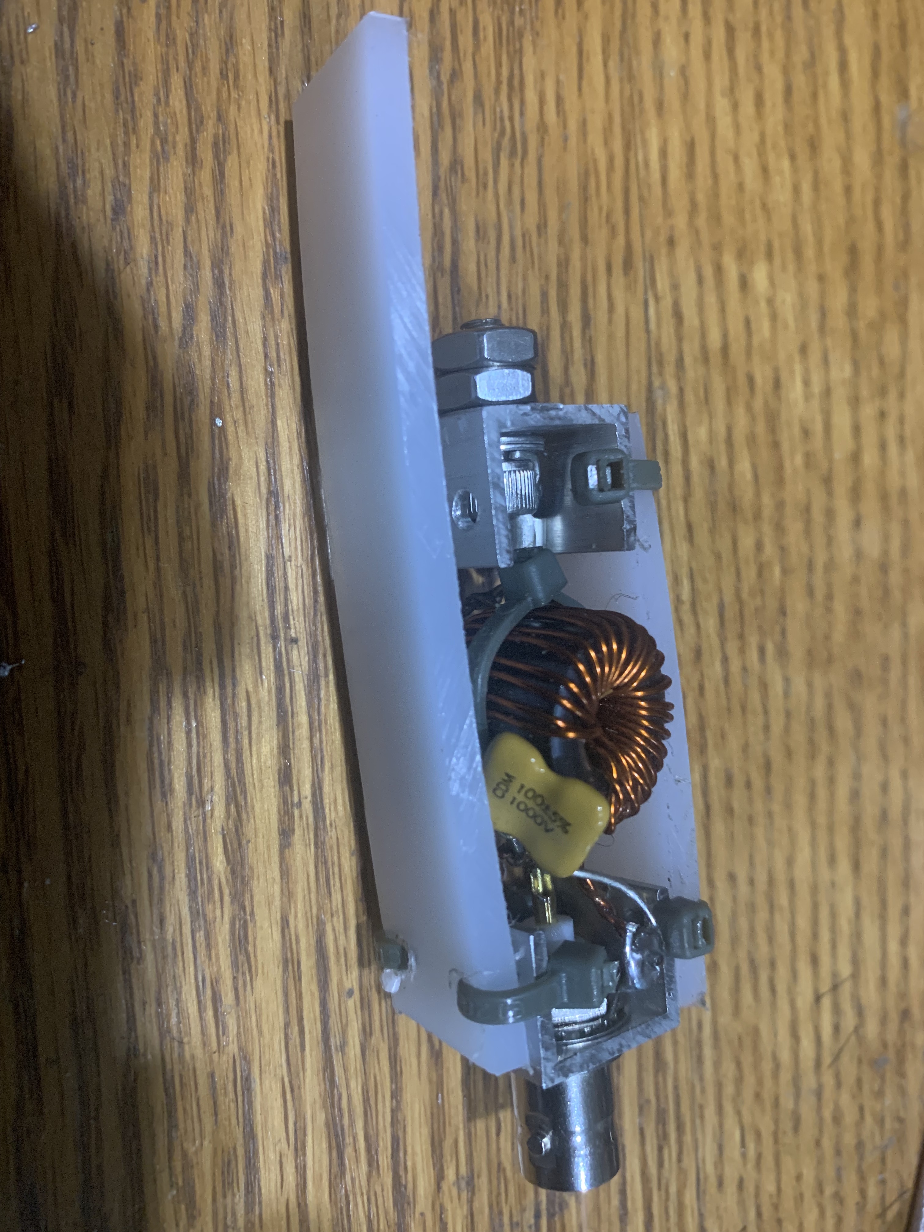
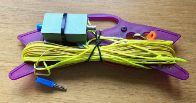
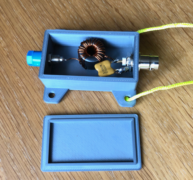
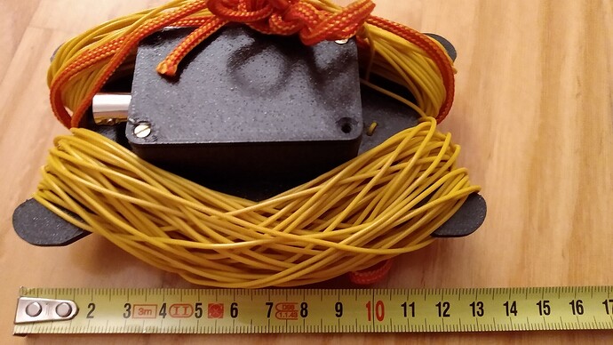
This is the first version in PLA, I need to re-print it in a more stable material (probably PETG will be OK for my use). Hence the ty-wrap to hold the lid on at the moment
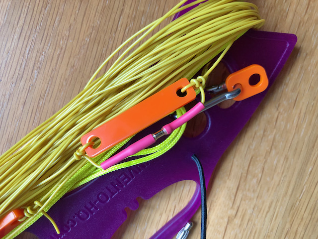
I also decided to go for a pluggable coil for now, in case I needed to adjust it (and also because when I searched my garage I couldn’t find the bit of 20mm conduit I thought I had!). I used the 2mm gold plated plug and sockets. So for now I can use the antenna as either a standard 40m EFHW or open the link for 17m. I’ll build the coil this week.
Apart from 40m, all the bands I can currently use it on are showing low VSWR, 40m is up to 2:1 at the top end of the band (but I think that matches one of your graphs), but my garden has quite a lot of trees so I can’t get it into as open an area as I would wish.
Thanks again for the nice info, and look forward to working with it!
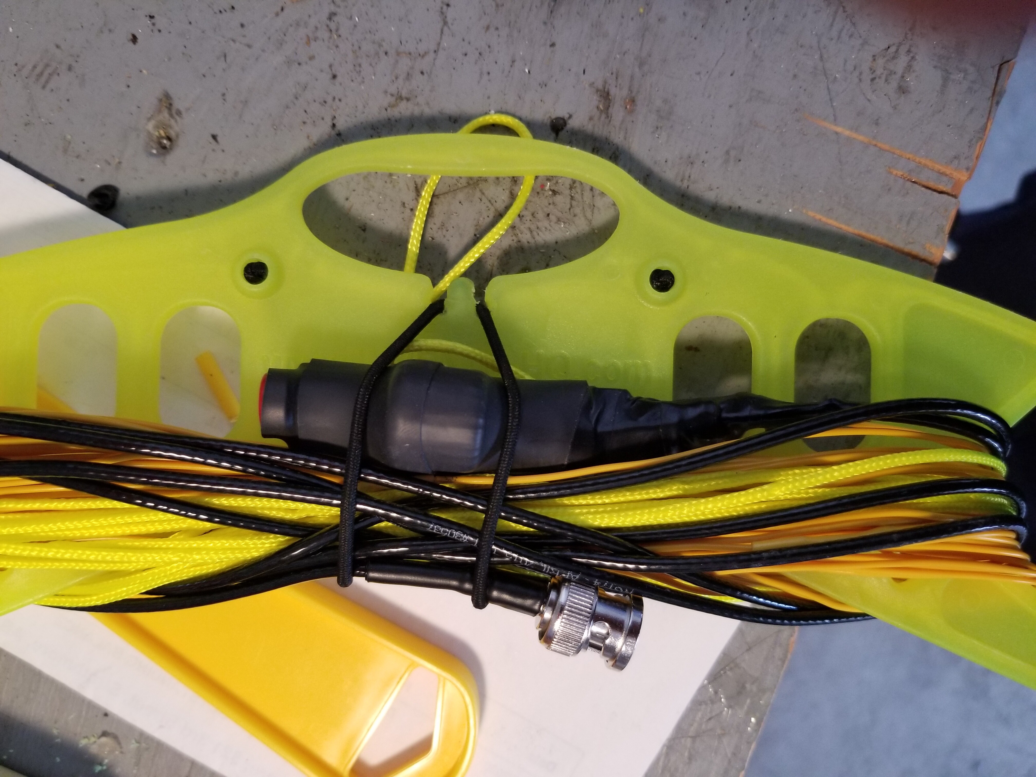
My attempt at the antenna. Pretty much same SWR sweep as NY4G when setup in an inverted V.
I should have run the small section of cord under the heat shrink instead of taping it after the fact.
Thanks for sharing and showing us your solution!
Also thanks to @VE6VID for his solution.
Your 3D-printed case looks very well engineered. And to use a pluggable coil is also an interesting alternative.
Concerning the high SWR on the 40-meter band:
I assume you measured it with an analyzer at the coupler feed point and added some piece of wire as “counterpoise” (e.g. 2m long).
When looking at Figure 31 (page 39) in the document, one can see that one field measurement shows also an SWR of around 2 on the 40-meter band. Therefore, your measurement from one location looks OK to me.
These different SWR values depend mainly on the environment and it is hard to predict, but can only be measured. For example, at the beginning of my experiments, I thought that on a flat field without trees or other obstacles I’ll see better values than in a dense forrest, but in reality, this is not always the case. There are so many factors involved.
I measured the SWR at the rig with a 7m RG58 feed (I’ll probably switch to a shorter RG174 but at the moment I can carry just this one feed to use use with another antenna as well). For now I’m going to run it with your dimensions and see how it matches in a few different locations before I worry about any fine tuning, from my early tests I don’t think it’s far off which is testament to your nice instructions.
I will pop the STL files for the 3D printed box on Thingiverse soon in case anyone else can make use of them.
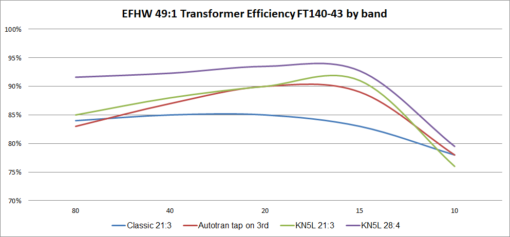
Following references to several articles on type of winding 49:1 transformer, and this excellent thread I decided to do some actual comparisons to have better handle how much more efficient actually is.
I used FT140-43 core as this is what I use for my portable operation. I wound Classic 21:3 style with twisted 3 turns and crossover after 7 turn. Next on the list autotransformer with a tap on 3rd turn. Finally I done two versions of KN5L style windings with 21:3 and 28:4 turns.
Its good to know that the KN5L method produces good results. Everytime I try to wind it I make an error someplace. Wire is cheap, so I will try another time.
 .
.