I’m an Industrial Engineer and the speciality I chose during my University studies was Electrical machines, such as transformers, generators, electric motors…
Unfortunately my 30+ years long professional activity diverted very much away from that domain and there’s little I know or remember about that now.
There are several different ways of coiling the windings around a ferromagnetic core and reading text descriptions of how it should be done doesn’t help me much to actually understand and visualize how a certain type of interlaced winding must be.
I’ve found this on the web and the cross-over winding is explained. However, the written explanation without an image doesn’t help me much.
I think your reference applies more to mains voltage power transformers rather than RF toroids.
However after a long look at the picture of KN5L’s transformer at the top of HB9EAJ’s referenced article together with reading the winding instructions I just about managed to figure out what was happening. What I can’t figure out is the reasoning behind any benefits derived from winding two turns in opposition at the bottom end of the transformer - you’d have thought they’d just cancel each other out…
I need to look carefully but whilst the magnetic fields would be out of phase and reduce the total flux (i.e. -2 turns and +4 turns = effectively 2 turns) there would be more capacitance. Maybe.
It does, but when I read the question about interlaced windings and remembered what we called in Spanish the “bobinados imbricados” in the mains voltage power transformers IIRC, then I searched something in English on the web and all I found was related to these sort of mains voltage power transformers.
However, I think the ElectroMagnetic principles remain the same and the results obtained with such interlaced windings are the same no matter how big the transformer is.
73,
Guru (still at the hospital but getting better and better)
Very glad to hear you are getting better Guru, my best wishes for your rapid and full recovery
I don’t think KN5L is using “interlaced” in any strict engineering sense, more as in a practical meaning - maybe as in “interwoven” or “interwound”? (Apologies for my linguistic shortcomings - I do appreciate my intended meaning may not survive direct translation to Spanish)
No need to apologize, Paul, but I honestly have no idea of what those two terms mean. I woudn’t even know it is Spanish, because, as I explained, it’s something I just learnt about in the University back in 1983 and I’ve never seen again after all this time.
But it’s true that the language barrier makes this type of specific technical discussions difficult due to not always knowing all the specific related vocabulary.
73,
After returning from a short activation with my daughter and looking again at the picture at the top of the page at KN5L EFHW Unun and reading again the Winding Instructions part, I still only understand the instructions well until “Wind the secondary over the initial six turns.”.
Like @GM4LLD, I also think that the capacitance increases when winding the secondary over the primary winding, but I’m also not 100% sure, since the impedance curve on the targeted ham bands is pretty flat. Maybe the best is I ask KN5L directly, also for another photo from another perspective.
First I thought even that the green enamel wire that is connected to ground goes between the two stacked toroids, but this is not the case.
I think he just stacked the toroids for better efficiency, so one could even try to use the 2643625002 toroid with thinner wire.
73 Stephan
Update: I just sent an email to KN5L. Will report back earliest after my activation by tomorrow or Monday.
I’ve got it Stephan!
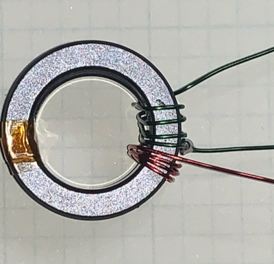
After a more careful reading of KN5L document and looking at the pictures closerly, I perfectly understand how the winding turns are made.
Once you have winded your primary turns, you have to solder the primary wire end to your secondary wire starting end and “Wind two turns of the secondary in the same direction as the primary/secondary turns.”
After having winded these 2 turns of your secondary as if they were an extension of your primary, you reverse the winding direction and wind all the rest of your secondary in that reversed direction. The initial 6 turns will cross over the ones you have already made (4 in your primary and 2 more in the initial secondary turns winded in the same direction of the primary).
"Wind the secondary over the initial six turns. Crossing over the windings inside the core forming a winding per winding interlace. Wind on six interlaces turns.
Continue winding the secondary windings to the desired turn count."
The text between " " has been copied/pasted from the original KN5L document.
I hope this will be of help.
Thanks a lot for looking at it again and your explanations.
The following part is still not completely clear to me:
How is the reverse winding exactly done? Should one attach/fix then the wire at the core (e.g., with glue), make a U-turn, and then continue the winding to the other side?
Update: I got a reply from John (I missed that mail before). He posted additional photos at Wind KN5L EFHW Unun. Very kind of him! I again asked him some more questions… I don’t give up until I understand it
I looked again at his measurements and they look really good, especially for the higher bands (compared to the standard winding technique). Like that, one can get rid of the primary shunt capacitor that doesn’t help to improve the efficiency of the coupler, it just helps to flatten the impedance matching towards the 10-meter band.
That’s exactly how I would do it. Since the 2 secondary turns will start at the primary end point, which is on the outter side of the toroid, I’d wind these 2 turns of the secondary and again on the outer side of the toroid I’d make a U-turn to start winding all the secondary to the opposite sense. Remember the crossover on the 6 first coils over the 2+4 of your primary/secondary must happen on the inner side of the toroid.
Good luck!
As I read it, there is no “U turn” in the winding - where it reverses, just cross the wire over the last turn and continue winding in the opposite direction, laying the wire between the last two turns and so on, crossing over each primary turn. I’m willing to be proved wrong, though…
Can’t get my head round winding capacitance and leakage inductance cancelling themselves out… anyone got any insights into that?
John told me briefly, thanks due to the capacitance of the tightly winding (assuming primary to secondary) there is no need for a primary shunt capacitor. This makes sense, but that’s only half of the story.
73 Stephan
Update: John answered me. Apart of confirming that there is no U-turn necessary, he elaborated about cancelling out the leakage inductance:
Close spacing windings will add capacitance. Adding a matching capacitor
is not required.
I see, so the capacitance doesn’t get cancelled out, but further built between the
primary and secondary? Did you find that out by experiment?
Yes. capacitance is required to cancel leakage inductance. Leakage
inductance decreases as primary and secondary are closer together.
Placing primary within secondary reduces leakage to the point that
winding capacitance cancels it. Had to wind several times to find
optimal winding configuration.
Fully agree. There’s no U-turn, just reverse the winding sense/direction crossing over the previous turns and then continuing until the secondary turns are all made.
I think the U-turn would surely cause unwished effects because the current would flow in the opossite direction to that on the primary 4 + 2 of the secondary start, thus cancelling the magnetic flux.
Well, I may make one myself one of these days to compare it with the 9:1 I currently use.
73,
Hi Stephan,
Thanks for the interesting design.
I built one and tested from ZL3/CB-527 on Saturday along with Mark @ZL3AB
We gave it a thorough workout and got very good results. Best DX to JA (S2S on 17m ) and YB (20m) and plenty of contacts to VK (30m, 20m, 17m) and ZL (60m, 40m, 12m, 10m).
It will be coming to other summits with me for sure!
73
Geoff ZL3GA
