Portable 7-Band EFHW Antenna

Hi Marek,

Thanks for publishing your results, very interesting!

What would be also interesting, if you would wind with this KN5L style, but using a core with another geometry, or stacking two of the FT140-43. Maybe the Fair-Rite 2643625002 is a bit small for this winding technique, but worth a try. I wanted to try it myself, but you know…

What puzzles me a bit is the low efficiency of your measurements on the 10-meter band for all of them. I guess that the winding capacitance is the biggest problem at this high frequency.

When looking at my calculations I did with Owen Duffys calculator using the #2643625002 core with a turn ratio of 24:3, one should never see less than 90% efficiency for your measured bands. I know, calculation is one thing, measuring another.

I had some email conversation with Gary Rondeau after he published this interesting article:

Several parts in his article don’t apply when doing QRP (like the voltage breakdown and heat dissipation) but it’s a very inspiring read.

To me the most interesting aspect of this KN5L winding technique would be to use a EFHW on the 6-meter band, but I don’t know if this really feasible, even after seeing his low measured losses below 50MHz.

73 Stephan

2 Likes

Marek,

I am curious as to what SWR distributions you were able to get with your different windings. I find that sometimes a compromise may need to be made between SWR and efficiency. In my experience, I have found the 24:3 winding ratio to give a good compromise. I also found that the #2643625002 core gives efficiencies higher than 95% in the low bands trending to about 90% on 10m with this 24:3 winding ratio. .I found that stacking two FT140-43 cores to be more efficient than a single core but winding ratios greater than 16:2 tend to give a worse impedance match across the bands.

Ariel NY4G

3 Likes

Hi Stephan @HB9EAJ ,

Not sure about poor 10m band efficiency, maybe this is mechanical due to the way I make them, or poor quality of capacitor or something else.

I will try different core FT140-43 or maybe two cores stacked up. I was also thinking about changing number of turns which overlay first 4+2 turns. At present there are four. I need to read KN5L article again and study his photos more closely. I will also try to make even shorter connections to the socket.

But first if weather is nice this weekend I will connect this transformer to my shorten EFHW8010 and see how it looks with actual wire.

Thanks for a new link, I will study it closely.

Ariel @NY4G my experience of balancing bandwidth and efficiency is the same. I tend to go for efficiency first. I will connect transformers to nanoVNA and fiddle with wires in order to get best readout. Then I check bandwidth and decide if compromise is needed.

Here is SWR reading on transformer in question (KN4L style winding) using 2500ohm resistor.

I used FT140-43 as opposed to #2643625002 core mainly due to the power handling capacity. Appart from SOTA from time to time I also do POTA and WCA and I run then 50W from IC7000. I wanted to have one set of gear for all portable activities. Maybe I will need to revisit this approach.

Thanks for comments guys. I will keep you posted if I improve things further.

73 Marek

2 Likes

Marek

I notice you used a resistor to simulate the antenna. The impedance of the antenna for the different bands do not stay constant and the SWR mismatch is better on some bands and worse for others. The compromise is in prioritizing which bands have to have the best SWR match on the real antenna. In my case I prioritize also on efficiency first but the SWR on 40m and 20m have to be acceptable. The other piece of the compromise is the SWR bandwidth. Fewer primary turns makes for a wider bandwidth in general and specially on 40m at the expense of efficiency. I do agree with you that the FT140-43 is a good all around core for its power handling capability and I found that out also to be good for both SOTA QRP and POTA running 50-60W and the occasional 100W. I do think that you have found a “sweet spot” compromise suitable for all your portable activities. I have similar results comparing efficiencies similar to what you plotted - Cool Things That Can Be Done With a NanoVNA - YouTube time stamp 25:34 comparing the #2643625002 core transformer versus the transformer supplied by LNR on their trail friendly 40-20-20. Thanks for sharing your results.

Ariel NY4G

2 Likes

Ariel @NY4G,

I finally watched your video and must admit that I am not sure if you can use your method for efficiency measurement of the transformer. I might be wrong by you measured return losses.

I am under impression that you need two identical transformers connected back to back and then by measuring S21 you have inline losses of two transformers. Dividing by two you get result for one. That what I have done.

After that I took one transformer as a reference point and measured different 49:1 versions. This time from the measurements I subtracted known losses of reference transformer, and I got losses for measured one. I hope you can follow.

73 Marek

2 Likes

Marek @SP9TKW

I tried both the back to back method and the resistor method. There appears to be an interaction effect when I have the transformers back to back. Owen Duffy recommends the resistor method and that seems to have more consistent results. It is somewhat sensitive to layout on the the S21 sweep and I try to keep my layout as consistent as possible. The efficiency appears to be related to core geometry and the number of primary turns. At the end, the measurements are more relative tan absolute since the resistor is only a simulated antenna. I used the Owen Duffy method in detail as described in his blog.

Ariel NY4G

3 Likes

Hi all,

First, many thanks for all your feedback and ideas that are very interesting and valuable to the community! Lots of things to experiment with.

In case you’re interested how quickly one can setup the EFHW antenna in inverted-L configuration, then please have a look at my latest video:

The main reason why the setup is so quick, it’s because I don’t use any guying, but the fishing pole support from Decathlon (links can be found in the document).

Further, I recorded four contacts using the TX-500 from Lab599 on the 40-meter band with @G0FEX, @F4WBN, @EA2DT and @ON4CB.

73 Stephan

10 Likes

Hi Stephan, thanks for your great video. Very enlightening.

Cheers Geoff vk3sq

1 Like

Thanks Stephan for sharing, indeed very informative.

I noticed that you setup antenna with end pointing towards North-West? Was it on purpose or just convenience?

73 Marek

1 Like

Hi Marek,

Thanks for your question that I sometimes ask myself, especially when I have different directions to choose from.

When you look at page 29ff in my document, thanks to the inverted-L configuration, the radiation pattern on 40m and below is pretty uniform. But on 20m (probably also on 30m, but I didn’t check the model for this band) and above you’ll get some directivity.

Usually, I look for the most easy setup (comfy place to sit, most open space, no tangling branches, etc.).
This is also kind of fair to the chasers on the higher bands, because over time, all directions are more or less equally “used”.

But of course, participating in the upcoming Trans-Atlantic S2S event, apart of the summit, I will definitely take the direction of the horizontal radiator wire into account.

73 Stephan

2 Likes

Hi Stephan,
Without having modelled and just following my instinct, I setup my inverted L for the Trans-Atlantic S2S event considering that a perpendicular to the plane determined by the inverted L is the one with the maximum radiation, but I’d like someone to simulate it and confirm whether my instinct is right or wrong.
Also, when I setup my antenna wire as a sloper, I always try to do it in a way that the wire slopes towards the direction I want to prioritize, i.e. towards the North-East for Europe and towards the North-West for NorthAmerica.
But, again, this is something I’ve never confirmed with a simulation, only with my own results and experience during my activations.
I’d like to see what computer simulators say about this.
73,

Guru

1 Like

The “instinct” may be good enough in the case of half-wave radiators. With shorter and longer antenna radiators than 1/2 lambda it is usually a bit more demanding.

For this reason, a user compass was added to my document “All-band antenna for the KX2/KXAT2”.

1 Like

I always have my “user compass” with me:


73,

Guru

1 Like

Hi Guru,

I agree with Heinz @HB9BCB that you have a good instinct, if you’re referring the higher bands.

Of course, when looking a bit closer, all gets a bit more complicated, since you have both vertical and horizontal polarization with this inverted-L setup.

In my document, the radiating wire length of the standard EFHW antenna is 1λ on 20m and shows a kind of heart shape in the horizontal plane (Figure 15).

Instead of spending countless hours with 4NEC2 or another modeling software (that may use another modeling approach), a website that I refer in my document, contains a bunch of different radiation patterns, e.g. for the inverted-L or the sloper.

Looking at these different patterns and comparing them with each other may train your instinct even more :smiley:

But when on an unknown summit, there are so many other factors like terrain, obstacles and ground conductivity, that the resulting pattern most likely will look different.

73 Stephan

3 Likes

Hi

Inspired by Stephan HB9EAJ EndFed construction i made one and i can say it work better than i expect. I have made some modification at loading coil, mine coil is build with core BN61-202 for get smaller and lighter overall antenna. Coil weight is 6,5 gram
I am a lazy at going to the switch for changing band :wink:
So i made some modification.
I have added experimental remote (via Bluetooth ) switch based on Atmel Attiny85 cpu and HC-05 module with small Meder reed relay. All is powered from small 250mA lipo battery .
Construction is in early field testing state , but it is working well.
At the moment i am controlling coil switching from bluetooth terminal app on android phone .
Later will build some dedicated app.
Device is working stable at qrp powered antenna, i do not know how it will act with more power - i do not use more than 5W :grinning:
Device weight is 14 grams Including battery , will be less after rebuild this test version into regular usable version :wink:

73 Grzegorz


9 Likes

Hi Grzegorz,

Thank you for publishing your remote controlled bypass switch. Interesting!

There was also a Canadian Ham that used a 430 MHz transmitter/receiver solution that I know of, but about one year ago, Peter @HB9TVK sent me as a gift one of his very well engineered Bluetooth switches to be tested in the field.

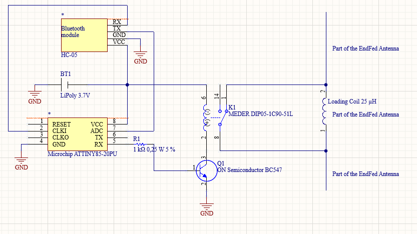
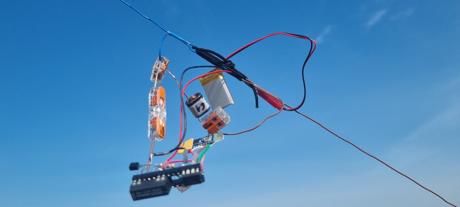
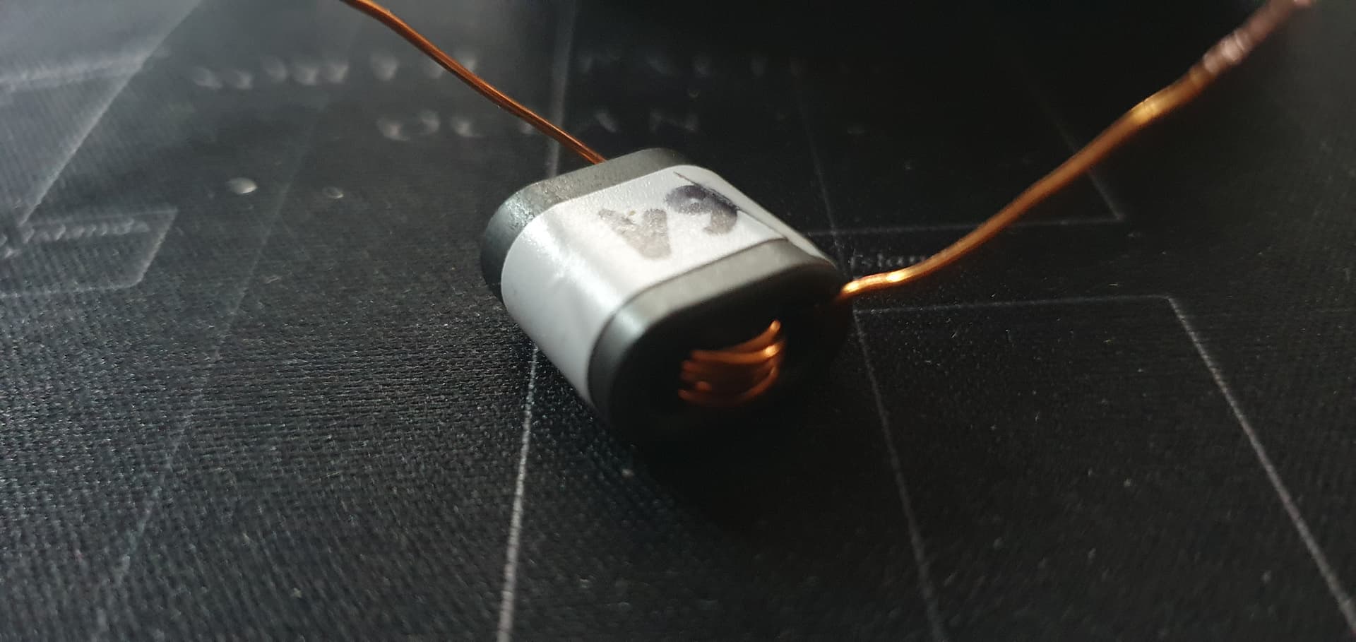
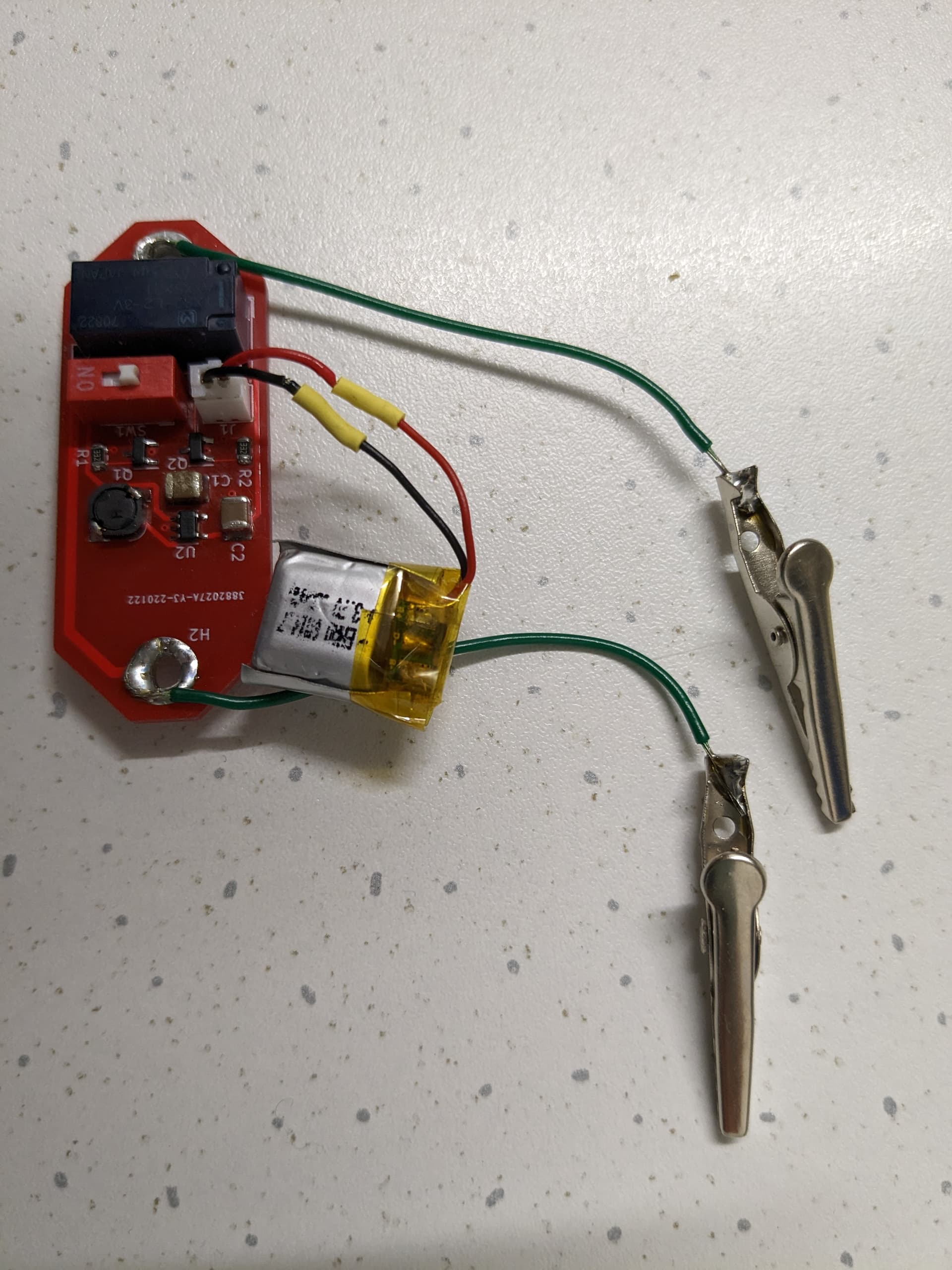
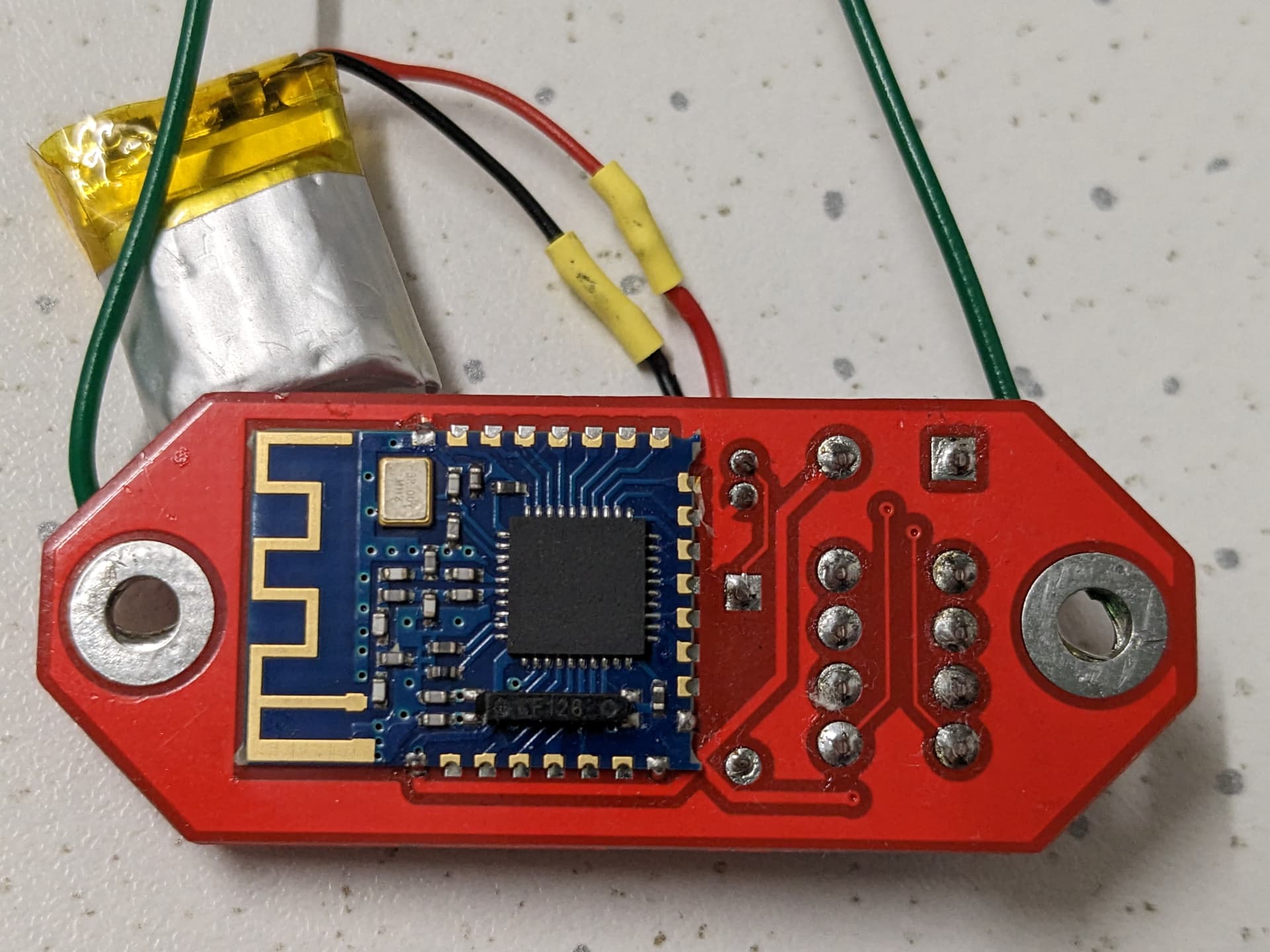
He built even a dedicated PCB containing a latching relay, the Bluetooth 4.0 module JDY-08, a DC-DC converter, some more components and a free hanging 50mAh LiPo cell. All in all it weights 9.2g.


Front side of the BT switch.


Back side with the JDY-08 BT module.

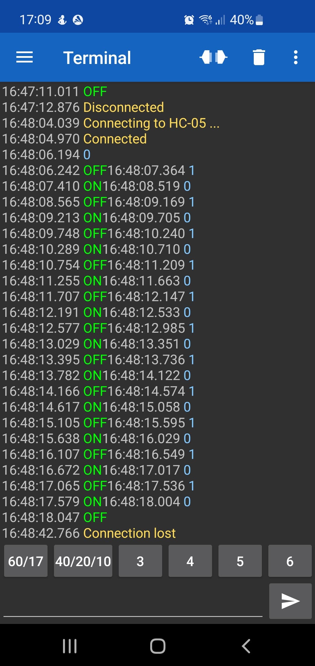
Like you, I used a Bluetooth terminal on my smartphone. In my case it was BLE Terminal PRO on Android. The advantage of this app was that it contained four programmable buttons. At the beginning I had problems to send the commands, but the app developer was very responsive and fixed some bugs. My initial plan was to write my own app, tailored for this purpose, but I wanted to initially test the feasibility of this project, so I chose a ready made app as prototype.

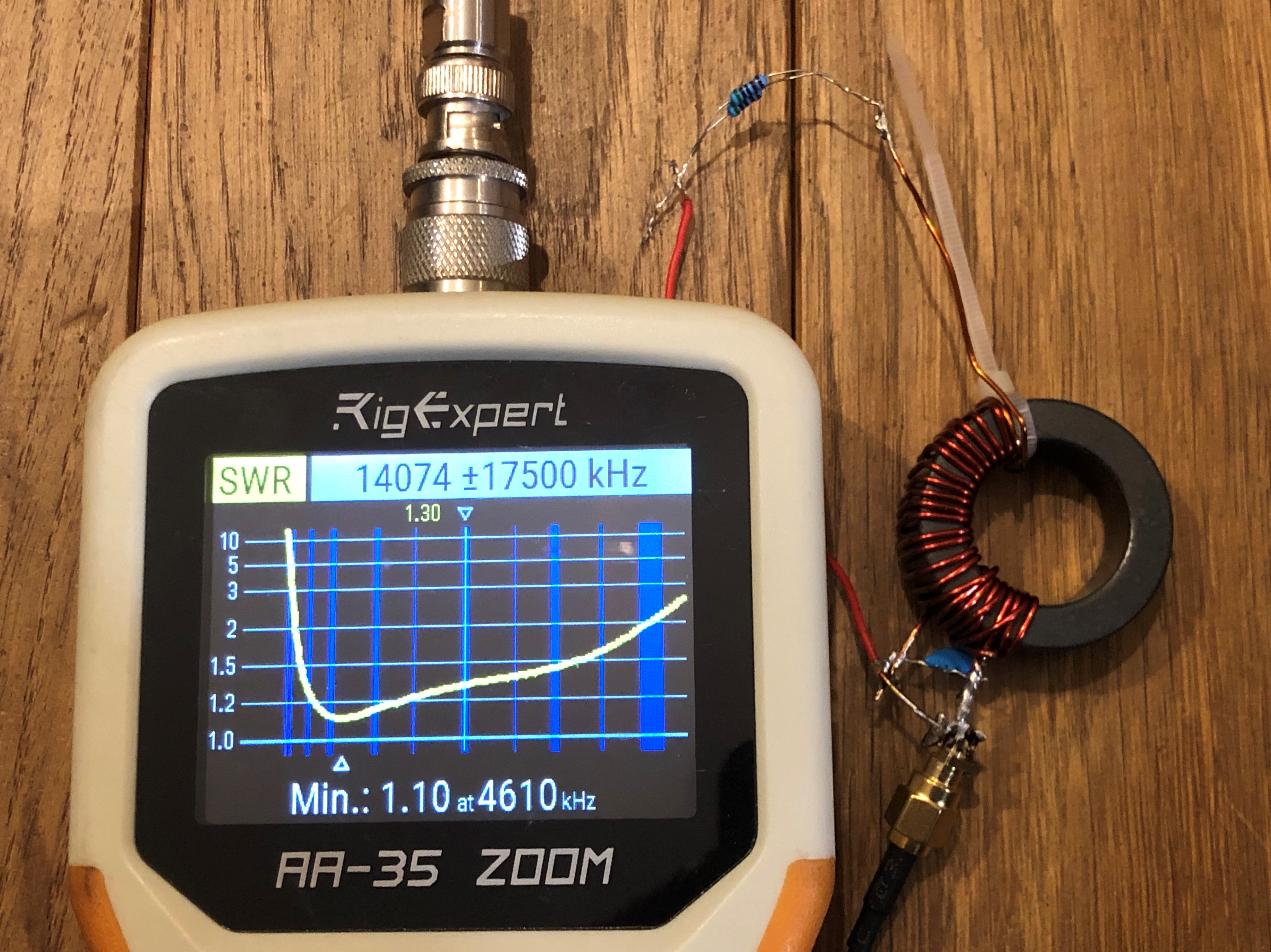
Peter and I were worried if the BT switch would survive 10W PEP, radiated by the antenna that was some millimeters away from the BT module. Luckily, on all the bands I tested it, it still worked afterwards.

Since the PCB contained also a step-up voltage regulator, I was also concerned about noise I might hear on HF, but luckily, not the slightest RFI signal could be detected on any band.

The max. distance that could be reached was about 30m, which is plenty for this purpose.

But there was one problem: there were sporadic Bluetooth connection problems which made the switching of the coil unreliable at times. Peter and me were not sure where the problem lied, but thought about a way to send back the status of the current relay status. For this purpose, Peter found a more modern BT module called JDY-23 that costs less than 1$ per piece, supports BT version 5.0 and needs even less current and could be powered directly from the 3.7V LiPo. We also thought about creating a 3D-printed coil that integrates the BT switch, but somehow I lost the track of this cool project. Maybe I focused more on the good time I’m having when doing SOTA :smile:.

While I still think that a reliable way to switch the coil using Bluetooth is a cool thing, the simplicity and weight (about 1 gram) of the manual push-bottom switch I use works just fine.

When changing the band segments, I have to get up, walk about 10 meters, grab the hanging coil and push the button. I used the coil with the manual switch since more than 300 activations, also in snow and rain, and never had a single problem.

Please keep us informed about your Bluetooth switch solution!

73 Stephan

8 Likes

Hi Stephan

Thanks for info about project of Peter in this matter :+1:
I am sure that moving that 10 meters to switch bypass is easier way but for me it cost time, time which is precious for me , time with microphone in hand :grin:
That is why i start to thinking of remote switching bypass.
Peters project looks very professional :+1:
Mine is still in developing mode , but i think that adding PCB will add more weight which i try to avoid.
Anyway thanks, and for sure i will post here my results :grinning:

73 Grzegorz

3 Likes

This is an excellent idea I also have been considering.
(The advantage of shorting a tuning coil vs using the relay as a link antenna, is that the voltage is much lower than at the end of the antenna.)

My multiband antenna uses 7x 4B1 ferrite beads (close to mix 61) as a ferrite rod. I use a slide in core instead of switching.
I got my 20m long EFHW antenna to have 40,20,15,10 with the core out, and 60,30,17,12 with the rod in.
Except on 60m, the cores carry little current, so you mostly have a full power antenna (for SSB at least)
A rod is probably better for heat dissipation. Using Kapton and teflon and magnet wire and not PVC will let it run to higher temps - “Mix 61 will withstand high power… Curie temperature > 300 C.”

An alternative to using the relay is to use a small motor to slide the core. There are really tiny motors and linear drives on alix. You are also not power limited by the relay. as no RF is being switched. Also you can actually tune the antenna a little.


An alternative to the whole bluetooth thing, is to make your antenna wire from a twisted pair of UTP. You can now feed the relay/motor power down the twisted pair. It is easy to feed the DC up through the EFHW transformer with a bifilar winding.

1 Like