I use a 91%:9% OCFD with a 49:1 matching transformer. I erect it in an inverted L shape with the 9% part touching the ground. It’s an excellent multiband antenna.
2 Likes
It’s probably an age thing, but I have this notion in my head that the radio amateur is mostly a resourceful type, but a long life has taught me to accept that exceptions to that rule must abound.
One thing I’ve often noticed in articles found during my online travels researching the subject of OCFD’s is that, when one cuts an OCFD for, say, the 40-meter band, it’s recommended to cut the antenna slightly longer than might “normally” be the case for a 40-meter dipole. This would bring the resonant frequency to just on, or just below, the lower end of the antenna’s principal band. So, for a 40-meter OCFD, cut the antenna to resonate on 7000 kHz, or even 6950 kHz.
This will still result in an acceptable VSWR range over the 40-meter band (especially if operating CW), and is done in order that the 3rd harmonic resonance on the 21-meter band is actually in band, and not too high. This is so often mentioned that it has become part of the radio amateur’s standard knowledge set - at least for those who are familiar with it. The curves I posted above take this into account. But you’re right - the 21MHz band frequency set is not an exact tuple of the 7MHz band set; so the radio ham gets creative, gets resourceful, gets the job done.
It can never be too often said - one should use the appropriate tool for the job, assuming of course that one possesses that tool.
2 Likes
Indeed - a good ham is an Artful Bodger! ![]()
In a previous thread I brought up the end effect as discussed above, and I mentioned there the “bodge” of adding a short length of wire, about 60cm, soldered to and hanging from the 1/3rd point of each arm of the dipole. This can be trimmed to give resonance in the 21MHz band without affecting the resonance on 7MHz. This little trick has a long history but seems to be little known nowadays.
2 Likes
Yes, I’m familiar with this little bodge, and had contemplated using something similar, at least with the linked dipole I have for 40/20/17/12/10 so that the 40-meter section could be lengthened slightly with some short plug-on tails, but in the end I didn’t bother since the Xiegu G90 has such a capable internal tuner. I know, it’s kinda lazy to leave that up to an ATU, but considering the major effort required in reaching a summit and setting up, it’s one less thing to worry about - at least for me.
Now that I’m using the 18% to 82% OCFD, I don’t even need to do that now.
There’s a similar bodge to be used with delta loops to connect/disconnect a hanging loop-tail in the main loop to account for differing grounds and set-ups. Haven’t gotten around to implementing that yet, though.
1 Like
It does not - at least not explicitly. However, a program could be devised to calculate the capacitive end-effect correction - and also an antenna apex-angle correction factor and length correction due to antenna wire insulation and more besides - for a given antenna, and to deliver the corrected lengths to a NEC engine for processing. Even if one did not do that, the end-effect correction tends to be rather small (i.e. close to 1.0) as this chart shows:
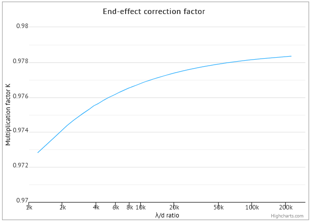
Typical values of λ/d (wavelength to wire diameter ratio) for the average SOTA wire antenna are between 3k and 50k, so the end-effect correction is typically in the range 0.975 to 0.978 - not a great deal of difference from 1.000, and some might say negligible, given all the other considerations in play.
As it happens, corrections for insulation (accounted for by NEC versions 4 and above) tend to be rather less likely to be negligible; but that, as they say, is another story…
1 Like
Perhaps I was not clear enough - I did not want to use an ATU on a 40M dipole but on something like a 66 or 44 foot dipole depending on bands of interest. That will minimize (or avoid) lobes.
73
John
1 Like
I’ve always been a believer in the idea of a doublet and tuner with its rapid band change agility - ideal for chasing. One wire does it all! I use 300 ohm window ribbon feeder because it has to follow a torturous route to the shack, but this brings me squarely to a major disadvantage. Yesterday was a wet day - a very wet day - and when I switched on the rig the SWR was just short of 3:1 when the previous evening it had been as near as dammit 1:1. If I look out of the shack window and see it has started to rain then I know I have to re-tune. I think that in the British climate 300 ohm window ribbon is not a good idea for SOTA. It doesn’t need to rain, if a cloud rolls in and the feeder gets wet with condensation then inevitably the antenna gets out of tune. I have no experience with 450 ohm window ribbon but I imagine that the problem would be less severe and probably close to negligable for traditional open wire feeders.
3 Likes
I have noticed that my 2m Jpole antenna, made with a 1/4 wave matching section of 450 Ohm window ribbon detunes significantly when it is wet eg in rain or condensate from wet cloud.
I tested it at home to prove which part was sensitive, by spraying it from a small misting bottle.
A 1/4 wave matching section, which has a high impedance at the “open” end is probably an extreme case, but the characteristics of the ribbon certainly are affected by water.
My home antenna is also a doublet fed with 300 Ohm window line, and a Zmatch. Curiously, I don’t notice much change to the Zmatch settings, wet or dry. Maybe by lucky chance I have avoided any high impedance nodes on the external section of feeder.
(It is not an RF designed aerial - I just ran out a piece of wire as long as I could fit in the garden, and cut it in the middle for a feed point. It is about 24m long)
2 Likes
With respect, you’re still not being clear enough to understand precisely what you mean; in any case, a 66ft dipole IS a 40-meter dipole, or very close to it.
Notwithstanding that, the 66ft / 44ft dipole antennas are used by many with good results, so you’re in good company.
1 Like
Me too.
If I tune it up on a dry day and then the following day it is wet then I may notice a slight increase in SWR but not very much, and not enough to need retuning.
I think that is probably it. I tend to use 20m for chasing as it’s the least noisy band at home so perhaps on a different band the rain would have more effect.
I did the same. It runs from a tree in the front garden, over the roof and to a tree in the back garden. It’s about 40m long.
3 Likes
Many radio amateurs have small and/or compromised QTHs like I do. Although I have a large back garden (by UK standards) there is only one way a ~40m-long wire could fit in the plot and be elevated enough to be usable - and that’s with the house and outside shack 4/5th of the way along its length.
When I first moved here, I put up an EFHW. Unfortunately, there’s no way to lay out or bury a ground plane here. It was too noisy so I put up a ~80%-~20% OCFD with the 4:1 Guanella current UnUn on the bungalow chimney stack. The ‘80%’ wire leg is tethered high up but sadly is still much lower than the continuous line of tall trees on two sides of my plot. The ‘20%’ is severely compromised and runs above the gutter line to the corner of the bungalow. Any talk of minimizing end effects or optimizing radiation lobes is a moot point.
The coax feeder runs down from the UnUn on the chimney then along my 1930’s iron rain gutters, across a 2m air gap bundled with AC power cable and collinear coax to the outside shack and in through a metal-framed window - all three of which would have adverse proximity effects had I used a ladderline. Thank goodness for the invention of coaxial feeders.
Fortunately, I’m not a dx’er - most of my activity is SOTA/portable - and the home QTH (with its S8-S9 noise on the lower HF bands) is only for SOTA chasing and regional QSOs.
2 Likes
Hi,
I’m using an off-center-fed-dipole of about 35 m length as my main antenna at my station and it works great without causing interference due to common mode current. I’m using a 600 Ohm ladderline, which has the lowest losses compared to other twinline feeders. That means that losses due to SWR are nearly unimportant on all bands between 60 and 10 m, but tuning is required!
With an appropriate tuner the currents can be forced to be equal and opposite on both wires of the feedline, so radiation is impossible. This can be easily measured for example with an MFJ 835, which I use permanently.
I am not using it in on summits or in the field. In spite of it’s superiority to all other kinds of dipoles which I have tried it is a bit difficult to hoist it up in the field. Due to the fact that built-in tuners in transceivers like in my KX2 cannot match this antenna under any circumstances I would have to carry a tuner with a high tunig-range with me and I don’t like the additional weight. I prefer verticals or an inverted-V for practical reasons.
If you will try using an off-center-fed antenna on a summit please let me know the results.
73 de Alexander, DL1AIW.
1 Like
I’m always prepared to try new things and this sounds interesting. I’ll give this a try because you’re someone with “clue” ![]() Make my life easy, what length are you using and what type of feeder ? Thanks.
Make my life easy, what length are you using and what type of feeder ? Thanks.
1 Like
That’s virtually an EFHW and I wonder if it also has characteristics of an EFHW, e.g. it should have a ground plane.
1 Like
It is literally an EFHW. I was being cheeky.
3 Likes
That was the conclusion I had come to.
Careful - someone might take your words at face value…
1 Like
Or the other cheeks…
1 Like
I’m glad you said that as I was scratching my head trying to picture what was where. And the 49:1 said the impedance was really high. I was concerned it was another sign of the onset of age related senility which is why I asked!
2 Likes
I have tried centre fed doublets may times, usually based on an 80m dipole length. Always a problem matching on some bands. I then tried this and it works really well…seems the science works!
1 Like
My first ham radio antenna was an 80m OCFD fed with 300 ohm twinlead. That was my first introduction to (unintentional) QRP. My homebrew tube transmitter had balanced output, but would not match the antenna. I was lucky to get a watt or so output, but I still managed some contacts.
Perhaps it could work with a good tuner, but I haven’t had a need to try it again in the last 50 years.
Even if the currents are equal on both sides of the feedline at the feedpoint, that doesn’t mean that the feedline is balanced. The reason is that the currents are not 180 degrees out of phase. You can see this with a modeling program if you build an explicit feedline using two parallel wires, rather than relying on the built-in feedline tools.
If you imagine the portions of the sine wave current distribution on each side of the feedpoint, those sine waves continue down the feedline: the current increasing in the side connected to the short end, and decreasing in the side connected to the long end. So, yes, without an explicit balun at the feedpoint, there is common mode current on the feedline, and it will radiate.
But that’s not the end of the world in many cases - the radiation still has to go somewhere. You may get some unexpected lobes and nulls in your pattern, but that’s often the case with portable antennas in field-expedient configurations anyway. And with an appropriate tuner, you probably can get it to work better than mine did.
2 Likes