Has anyone tried this and can offer any words of wisdom please?
Dave
G6EGM
Has anyone tried this and can offer any words of wisdom please?
Dave
G6EGM
Years ago I built a current sum antenna (Stromsummenantenne, Windom-like, but different feed point) with a radio/TV twin feeder. With the TRX a 4:1 BALUN. Works perfectly.
73, Peter - HB9PJT
Hi Dave, I haven’t tried this, and I don’t pretend to be wise!
That said, an OCFD is not a balanced antenna, so if you feed it with twin line, the current flowing in the feeder wires will not be equal and opposite. That means that the feeder will radiate to some extent, and will also pick up noise on receive.
Neither of those effects will prevent you achieving a match, but might be a nuisance…
Hi Dave
This article from W5DXP covers what you want to do I think:
OCF Dipoles Fed with Ladder-Line (eham.net)
One reason people like off-centre-fed dipoles is that they are multi-band. If that is the reason that you want to create one, don’t forget that a normally centre-fed dipole when fed with ladder line (as per the well-known G5RV design) is also multi-band.
73 Ed.
The advantage of feeding with radio/TV twin lead is the lower weight and the lower losses in the antenna cable.
73, Peter - HB9PJT
Check this out:
wanna try to build one too.
73
Julian
You can put a current choke at the feed point. It doesn’t need to be transmission line, just a pair of wires wound through the ferrite core N times like you do with coax, and joined to the tv ribbon.
(You will be wanting 2x as many turns as you would use for 50 ohm coax btw as Z is higher)
In previous years Fritzel’s FD4 was very popular… as an alternative to W3DZZ.
These antennas could be tuned well with the tube amplifiers of the old radios.
However, the FD4 soon gained a bad reputation because Fritzel’s balun had a design flaw. It did strong TVI and BCI.
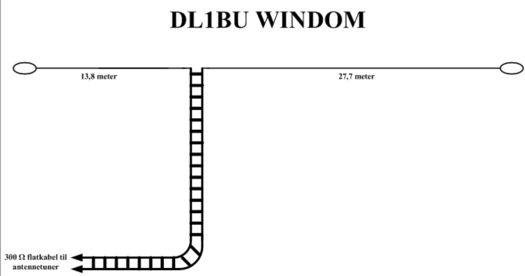
DL1BU then recommended feeding the FD4 with a 300 ohm feeder line. That helped many.
73 Armin
Thank you everyone for your replies, I will try some of the options suggested and report back in the new year
I use mostly off-center-fed-loops at fixed home stations. Similar to these, but wire length is maximum I can fit into the space.
73, Jaakko ac1bb/oh7bf
¤That said, an OCFD is not a balanced antenna, so if you feed it with twin line, the current flowing in the feeder wires will not be equal and opposite. ¤ I dont agree with this. Since the Windom antenna is fed with the balanced side of a 4:1 balun it must be because the feed point of the Windom antenna works as a balanced point. I would guess that the only feed point that is not balanced, is at the end of the antenna. In my ignorance I try to explain an antenna as similar to a bathtub where the water is moved to go back and forth between the ends of the bathtub. In the center there is much speed of the water and no change of water level. At the end you have water going up and down and no side movement. Comparing the speed of the water with current/amperes in the antenna and the waterlevel with the voltage in the antenna, we see the different impedances at different points along the antenna. When we cut the antenna in any feed point, the current and voltage should be the same on both sides of the cut, but with very different impedance from where the cut is made. I plan to feed my Windom antenna with 400ohm or 300ohm twin lead and place the 1:4 balun where the line enters the house, and use 50 ohm coax from there to the tranceiver. I hope I have not misunderstood completeley and am sorry for the long explanation. Gudleik LA6FTA.
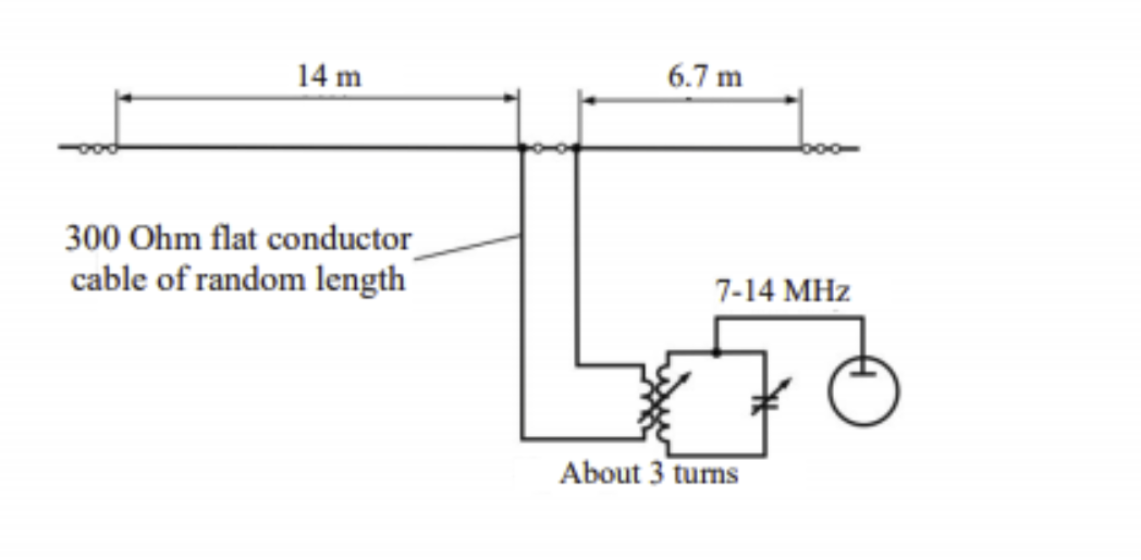
The thing about the so-called Windom is that you need to be heedful of the length of the feeder because it acts as an impedance transformer, in other words the feeder may be attached to the antenna at a point where the impedence is the same as the impedence of the feeder, but the impedance at the other end of the feeder will depend on the length of the feeder. If you make a 40m dipole fed at the one third point then the impedance at the feed point will be about 300 ohms, it will also be about 300 ohms on 20m and 10m. If you attach 300 ohm ribbon to this point the impedance at the other end of the feeder will depend on the length of the feeder. If the feeder is an electrical half wave long at 40m then the impedance at the other end will also be 300 ohms on 40m, 20m and 10m, and a 4:1 balun will match it to the transmitter. A useful variant is to make the feeder a multiple of a quarter wave on 15m, this will then match the rig on 15m with a 1:1 balun, and replacing it when needed with a 4:1 balun will be a match on 40, 20 and 10m. This is the old G0FAH antenna. Still, why faff about, just use a balanced ATU!
If the feeder has the same impedance as the antenna then it will present that impedance to the other end of the feeder regardless of the feeder length. So use 300 ohm ribbon with a 300 ohm antenna and it will be 300 ohm at all points on the feeder. It’s only when the feeder and antenna have different impedances that the length will matter.
In my above reply I did not go on to discuss the unbalanced nature of the antenna. It is simple really, and easily visualised. The one side of the feeder at the feedpoint nearest the end will have a current rising to maximum, the other side will be falling from maximum, they will be equal at the electrical half wave but nowhere else. The result is that the feeder will radiate like a vertical in the conventional T shaped diagram. However this is not necessarily a bad thing, it will make the radiated signal a mixture of vertical and horizontal polarisation and make the radiation pattern more isotropic.
I wouldn’t both wasting your time trying to feed an OCFD with 300 ohm twin. As someone who who has used the G5RV and an 80m top fed with open wire 300 ohm twin in previous decades (from home but NOT FROM A SUMMIT), albeit my OCFD has a “centre” support for the balun, I can testify that fed with 50 ohm coax with a coax wound ferrite choke 20 feet down the vertical coax feed from the feedpoint, the OCFD antenna represents the best possible compromise for general purpose use from 30m to 80m (and from 20 metres up if a beam antenna is not available).
The coax fed OCFD is not an antenna that I would dream of using for activating however… although I did use one once as an activator from a drive on summit, for an EU Activity day (Organised by the OE Association) because my built in ATU on the FT-991A would tune the antenna on any HF band).
73 Phil G4OBK
I have used a coax fed 20m OCF, and I agree that used as a horizontal antenna it is problematic for SOTA, with the weight of the balun at the top of a flexible pole. However I found it quite successful if I used the long arm as a vertical and the short arm at 90 degrees, as if it was a radial.
Needless to say, I like playing with antennas!
Come on guys. This unbalanced antenna current feed talk is rubbish.
It is in the same category as claiming reflected power is responsible destroying your pa when it’s actually running it on a bad load line that does the destruction.
Regardless of where you feed an antenna the current flowing in say the right hand direction has to be of the same magnitude as the currently flowing in the left hand direction.
Kirchoff had something to say about this.
If you have a feeder with balanced currents the antenna currents are balanced. Current in has to match current out, otherwise charge builds up and BANG.
Pre WW2 open wire line was used to feed all kinds of radiators, including the end fed Zepp. Feeding any OCF doublet with OWL is fine. 300 ohm ribbon was a cheap, ready built alternative, albeit more lossy. We have forgotten some of our technology.
I use a 5 MHz doublet, off centre fed with home brew OWL and have had DX contacts on all bands from 3.5 to 50 MHz. Those old timers understood antennas.
73
Ron
VK3AFW.
![]()
Ron, you are thinking about an OWL feeder as if it is some kind of hosepipe. It is rather more complex than that. In OWL feeder to the centre of a dipole antenna there is a continuous succession of points along the feeder where the electromagnetic field from one side of the pair is balanced by an equal and opposite field from the other. If the OWL is connected away from the centre of the dipole then this balance does not exist at any point along the feeder and the feeder radiates.
Draw it out for yourself, the horizontal antenna and the two feeder wires. Represent the current as a dotted line curving from the antenna at the ends to a maximum at the centre. Now since the feeder attachment point is a break in the antenna, it will be a break in the dotted line, so at the feed point continue each of the two parts of the dotted line down the nearest half of the feeder. You see that they are out of step with each other.
If you are running 100 watts then that wattage will still be radiated but only part of it will be from the antenna which will presumably be high and in the clear. Part will be radiated from the vertical part of the feeder and will be vertically polarised, and part will be radiated from the part of the feeder routed at a lower level to the rig. This will radiate too, with mainly horizontal polarisation but as this part of the feeder is lower this power will go to warm the clouds.
As I indicated above, this is not an entirely bad thing, all the power does go out but in different ways, only part of your output will go out in the way that you would have expected from your antenna, part of your power will behave as if radiated from a vertical and may even be more effective than the main antenna at low angles for DX or from off the ends of the antenna, and part of your power will be suitable for NVIS. The antenna system now does three jobs instead of one, but none of these three jobs will be done as well as the balanced equivalent will do one job. For SOTA it is likely that the OWL will be a lot shorter than at a home station, so the third part, the NVIS, will be negligable. If the feeder is very short then the vertically polarised radiation will be less than the horizontal polarised radiation from the antenna. It all depends on how you set up the antenna system - system because the feeder is now an active part of the antenna.
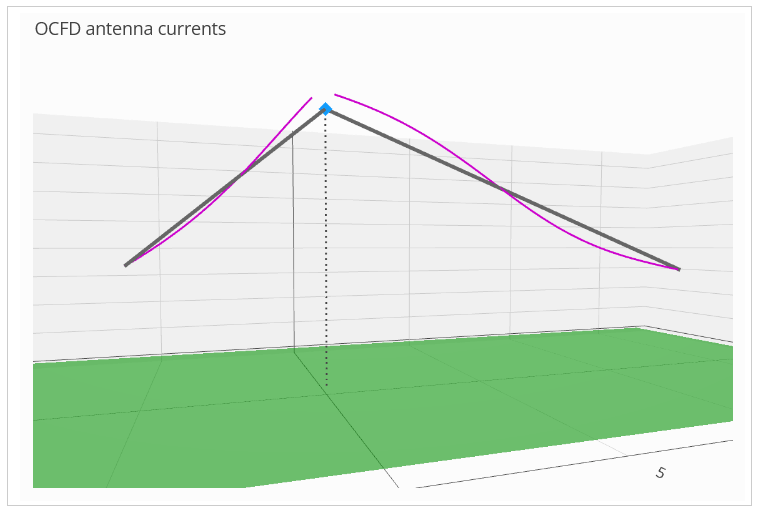
The NEC programs would agree with you on this. Here’s a 33/67 ratio OCFD with sloping legs cut for the 40 meter band, operating on 15 meters:
It doesn’t matter where you cut it (my favourite is a 18/82 ratio), or at what angle the legs are at, the result is always the same - at the feed-point, the currents are equal. Turns out Kirchoff knew a thing or two.