It all depends what one wants from an antenna. The OCFD style of antenna has a hundred-year old history, and with good reason: it can deliver more than “just” a center-fed dipole, by being naturally resonant on more than just one band or frequency range.
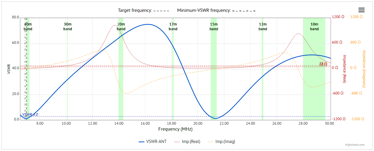
To illustrate this point, here’s a VSWR scan of a center-fed dipole cut for the 40-meter band, with arms sloping at 30° to the horizontal, and center-height at 15 meters AGL:
The center-fed dipole is naturally resonant on 40 meters and also on 15 meters, due to the harmonic relationship between the two bands. All well and good … but there’s more.
Feeding this same antenna off-center, one can achieve resonance on more than two bands, if one chooses an appropriate ratio of the lengths of the two arms of the antenna.
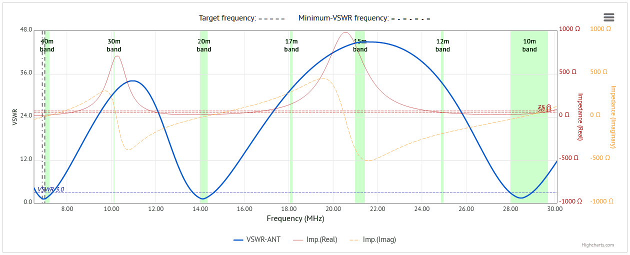
For instance, here’s the VSWR curve of the same antenna, now fed off-center, with arms of 33% and 67% respectively (the most-often quoted or chosen ratio):
Things look a little more interesting now: this antenna is resonant on three bands 40m, 20m and 10m, although we’ve now lost the 15-meter band.
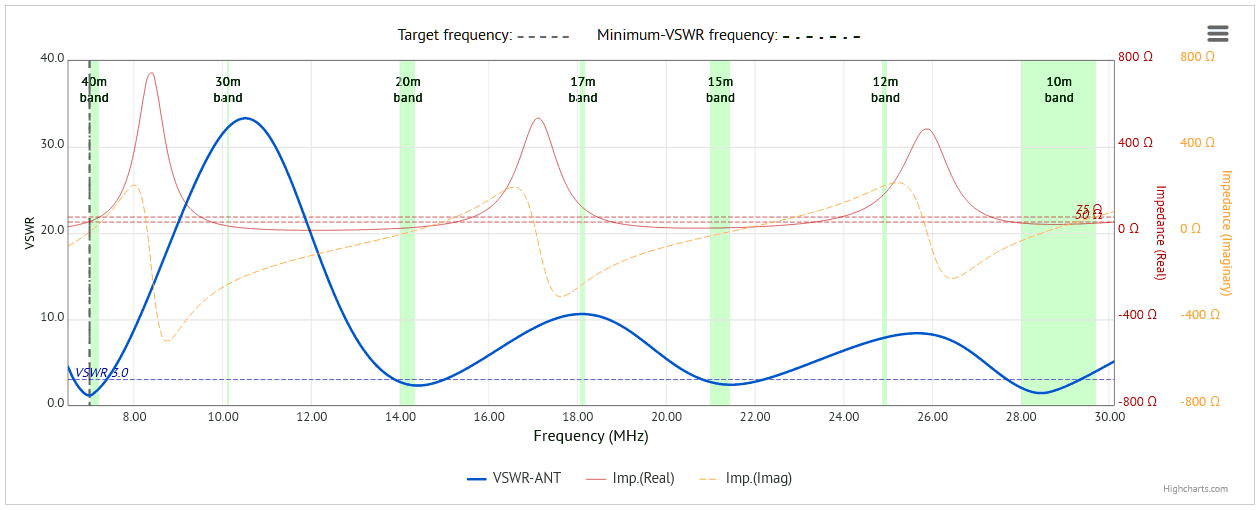
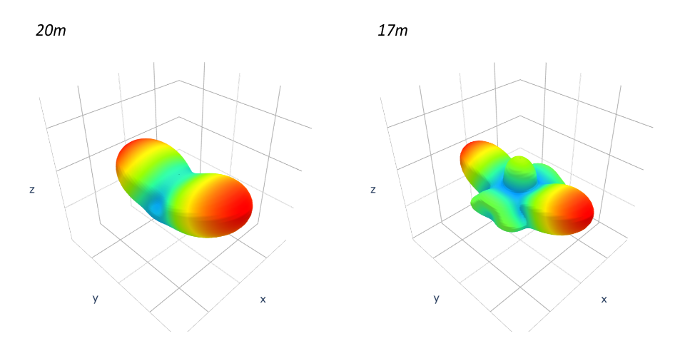
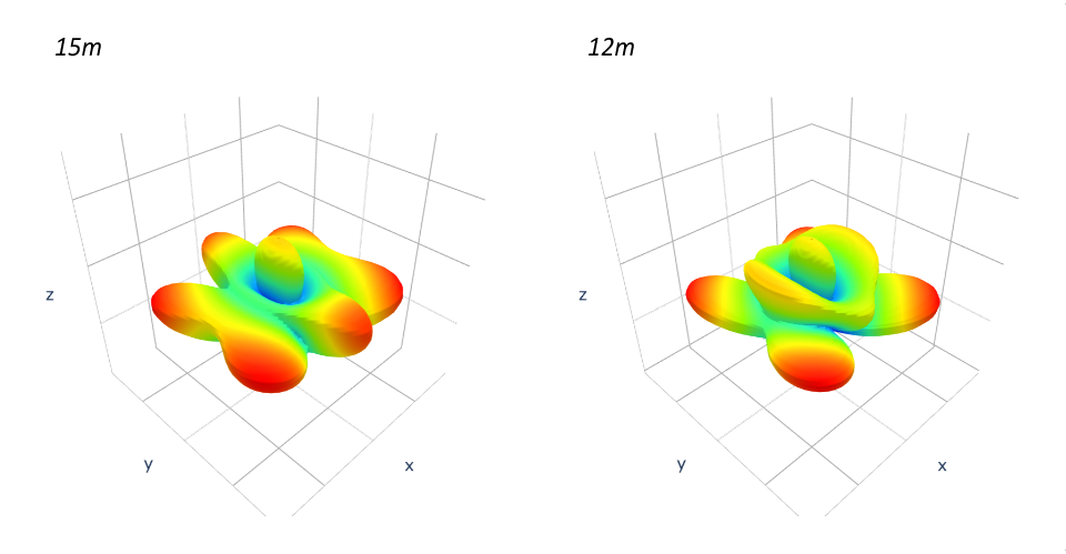
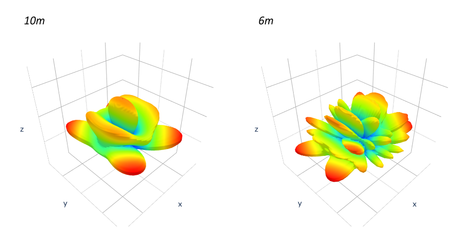
Here’s a further example, a 18% to 82% ratio split OCFD - my particular favourite:
We now have an antenna which is naturally, in and of itself, resonant on four bands: 40m, 20m, 15m and 10m (it’s also resonant on 6m, but who ever uses 6m, right?  )
)
So, the OCFD can be resonant on more than one band, no tuner required on those bands - one just has to decide how to arrange the two arms of the antenna to achieve resonance on the bands of choice.
EDIT: just to be clear, these curves show VSWR at the antenna feed-point - if using a lossy coax feed, the values at the TRX end will be (even) lower than those displayed here.
Cheers, Rob
NEW EDIT: Graphics updated, without losing the import of the argument.