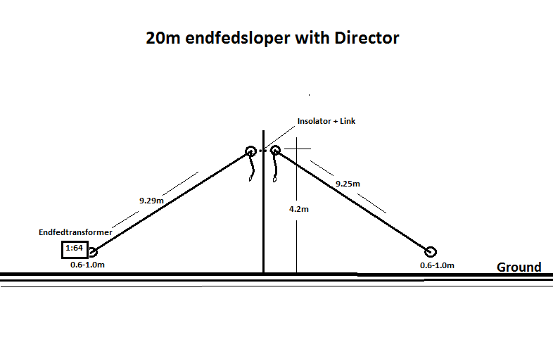
Last year I played around with the VP2E-Antenna and took informations from Ed DD5LP article. I took the dimensions for 20m, trim and cut it in the garden.
I got dips at 5 mc and 14 mc but the SWR was 1:2,5. I moved the feedpoint up and down the wire, I can’t get no better match. The impedance was 110-125ohm. Many russian hams feed the VP2E-Antenna from one end with L-C matching unit, and I tried to use my 1:64 endfed transformer and everything works fine, low SWR, nearly 48ohm, perfect.
I read an article in an antenna book, about a half wave sloper dipol with a director element, with gain and low take off angle. The idea was to mix both antenna types.
First I cut the radiator for 20m resonance, than I close the link on the top and cut the other wire for 40m resonance. Both wires linked together also still usable on 20m.
Can anybody model this antenna?
link open for 20m
link closed for 20m
link closed for 40m
Questions:
1.optimal antenna height? gain radiation pattern
2.characteristics on 40m (like inverted V?)
3.Is there a low take off angle and gain for 20m, like the VP2E-Antenna?
I ask for help, because I can’t use the 4nec2 Software yet.
Thanks in advance!
Hi Thomas, I think, your new antenna is an end-fed half-wave sloper antenna for 20 or 40m it may operate with some directivity because of the parasitic element on 20m when the link is open.
This will be (I believe) a horizontally polarised antenna, rather than the vertical polarisation of the VP2E and may have a higher take-off angle. The VP2E is critical on its height and the height of the ends of the wires and hence also the angles. With your EFHW - I’d say get the mast as high as you can for the best performance. As is generally the case for horizontal and sloper antennas.
Oh, and what are you using for the counterpoise - hopefully not the braid of the feeder coax or the case of your rig? I’d run 8 (or at least 4) x 5-metre wires out from the earth side of the UNUN transformer.
As per my experiments, the VP2E cannot be made multi-band by adding links, however, the EFHW certainly can.
Apart from the influence of the “parasitic” wire on the base-fed half-wave sloper, there is actually nothing mystical about it.
The base-fed half-wave sloper, with an angle of around 20 degrees, is much too flat to live up to its name.
The unused wire acts as a parasitic element and, because it is arranged just as flat as the sloper, is just as disadvantageous.
The somewhat “mystical” functionality of the VP2E is nothing more than an off-center fed full-wave antenna. The properties therefore differ only insignificantly from those of the end-fed full-wave inv-V antenna.
The main feature of the VP2E antenna may be that the radiation angle, which is relatively flat for a full-wave antenna, can be achieved with such a short mast. This is particularly interesting with VP2Es for the longer bands.
BTW, A simple 14 MHz GP with 2 radials (feed point at 1.20 m) is equal to the VP2E in terms of gain, but with a vertical radiation angle of only 20 degrees…
What else should you add? Have fun!
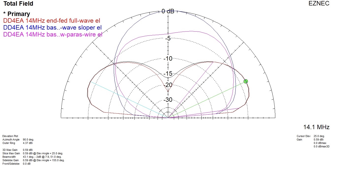
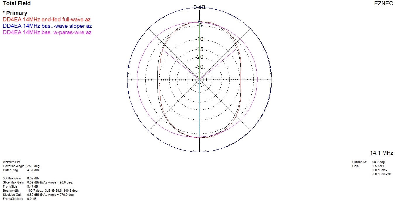
Legend to the EZNEC diagrams below
Primary is for VP2E (black)
End-fed full-wave inv-V (red)
Base-fed half-wave sloper without the presence of “parasitic” element (blue)
Base-fed half-wave sloper with “parasitic” element (pink)
Hi Heinz,
I’ve always had the impression that the base-fed halfwave endfed sloper has some directivity towards the direction determined by an imaginary vector from the base of the supporting pole to the base-feed point.
My experience during SOTA activations tends to confirm this. When I setup with my wire sloping towards the NW, I usually have better DX with North-America than when I setup sloping towards the East or North-East, which is what I do in the mornings in order to optimize signals with Europe.
But looking at the EZNEC plots you’ve posted, it seems like there’s no such directivity in one sense over its opossite.
What’s your opinion and interpretation of those plots and your own experience about this?
Thank you.
73,
The magnitude of the directional effect of a sloper (1/4 or 1/2 lambda) is quite simply dependent on the angle of inclination of the sloper, the directional effect being greatest at an angle of inclination in the range of 45 degrees.
EZNEC and comparable proven tools are certainly not mistaken in this matter.
Still on the (long) “To-Do” list! Every time I wanted to try a comparison against the linked dipole, something went wrong - either one of the antennas had issues or the weather broke or access was not possible to the summit. To do a proper test I need a large summit area (or portable operations area).
Now with a combination of the weather turning wet and cold and COVID being totally out of control in Germany, I don’t expect to be able to get to this action item in the near future.
One test I did get a conclusive result on though was that making a linked 20/40m version of the VP2E isn’t possible. I am now back with two separate single-band antennas, each with their own mast and mast support.
Hi Guru,
The other factor could be the ground type and any slope or rising ground creating a blockage in a certain direction from where the antenna is set-up. As always setting up the same antenna on different summits it can work in different ways.
I have read that when used with a single counterpoise wire, the direction that is laid in can create some directivity on an EFHW, I have never seen this but I have not used EFHW antennas for several years, preferring the linked dipole.
Getting back to the VP2E, I have the feeling that it works generally better than my Inverted-V linked dipole - whether than is directivity or simply that there is twice as much wire in the air, I have yet to find out.
73 Ed.
Hello ED,
nice to hear from you again. To your question: I feed all my homebrew endfedantennas with no Counterpoise, or a lamda 0,05 counterpoise and 2-4 m RG 174 or RG 316 coax. The coax may act as a counterpoise, but at qrp level 5 watts or a bit more, I never had problems.
to VP2E antenna,
I tried really everything 1. Mast up and down. 2. Ends up and down. 3. loading with a klapp ferrite choke to find the best spot. I found it in the middle with 110-125 ohms. perhabs it is
the ground in the garden or they are no 50 Ohm feed anywere?? I spend a lot of time with this antenna, now I feed from the End. OM heinz HB9BCB(tnx Heinz) did the moddeling for 1 Lamda endfed and VP2E 1 Lamda offset Dipol. Pattern looks nearly identically, all ok.
73 Thomas
Hi Thomas,
With the VP2E the best SWR I could get was 1.7 or 1.8:1 on the 40m version. The 20m version was a little worse. I wondered when trimming the ends of the wires whether I should change the feed-point position as well. This may have made a small difference. I should have noted on the antenna analyser what the impedance was but I would guess it will be somewhere around 100 Ohms. I could try adding a q-section or simply feed the antenna with 72 Ohm coax instead of 50 Ohm.
As you say at QRP levels using the coax sheath as the counterpoise on your end-fed wire is quite normal rather than adding an extra wire. It might be worth adding a “proper” counterpoise to see if it improves the antenna though. Another point is that if you ever change the coax feedline to a different type or length, this could de-tune the antenna but when set up with a standard counterpoise wire the length of the coax feed will no longer affect the antenna’s tuning.
Hello Heinz,
Wow, that was very quick. Thank you for the modelling, that cleared it up for me a lot.
The VP2E antenna, low mastheight, low angle, outperform a GP ? 50 ohm feed? a little long for 20m Antenna.
I got hooked in a miracleantenna. I spend a lot of time in the garden, weather was sunny and nice, nothing to worry about.
The results for me 1. full wave endfedsloper 20 m low height ca 4 m
2. half wave endfedsloper 40 m high height ca 6m or more
3. link in the middle, a gimmick, not needed
2 Antennas with one wire, it`s ok.
Yes heinz, I have build GP antennas for 20m +17m with 2-3 Radials. That was fun, cutting and trimming is easy. The problem is always the pole, on hiking trips,a 6m glasfasermast
is the max, I carry(550gr.). A little low for GP20m, but I got low elevated radials, for GP 17m
it is better. My all in one Antenna is a 7.6m Rybakovantenna with a 1:4 balun and a tuner.
Yes, there are losses in the balun and tuner, but you got easy multiband.
Thank`s for your Help, and I hope to get in the 4nec2 software soon.
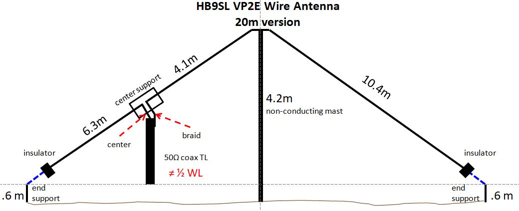
Does anyone have a NEC (preferably EZNEC or AutoEZ) model for the 20m version of the HB9SL VP2E antenna they could upload? Apparently most installations don’t include chokes or baluns. It seems likely that common mode current (CMC) will affect SWR, radiation patterns, and possibly cause RFI at the rig. Simulating coax CMC in NEC requires a “workaround” of adding a wire the length of the coax or the length of the coax to a choke. The “CMC wire” is specified with an equivalent diameter of the coax braid (6.096 mm in the case of RG-8X). The magnitude of predicted current flow on the CMC wire can give some insight as to the impact of CMC on the antenna. Analyzing the model with and without the CMC wire can give additional insight into the the impact on SWR and radiation patterns.
It’s difficult to see how a gain above unity (0 dBi) is possible with the antenna at elevation angles less than 40-45 degrees.
Yes and no, that’s why this comment prompted me to review my EZNEC v.6 model, which was defined for the 14 MHz version of the VP2E antenna.
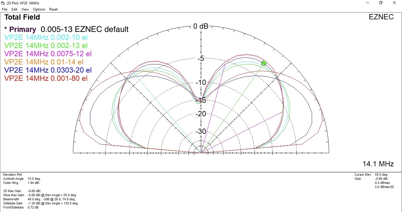
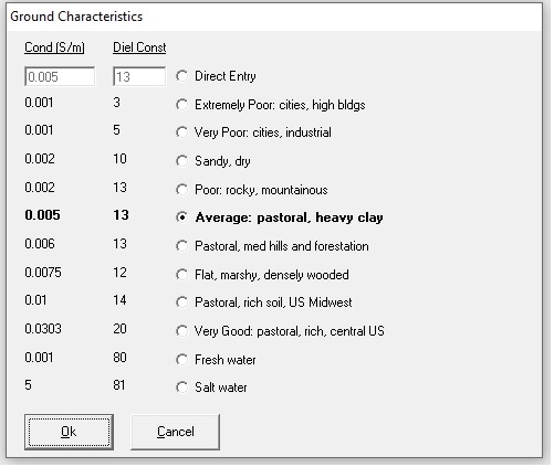
And there was actually and unintentionally chosen the conductivity/permittivity values of 0.0303s/20 … sorry.
I usually skip this setting because only in special cases do I not use the defined default value of 0.005/13.
As a small “compensation”, the diagram below shows the vertical radiation plots with different conductivity / permittivity values.
As you can see, there are only insignificant differences over a large area - and only those few can consider themselves lucky who can erect this antenna over a very good conductive ground.