Leveraging your VNA investment

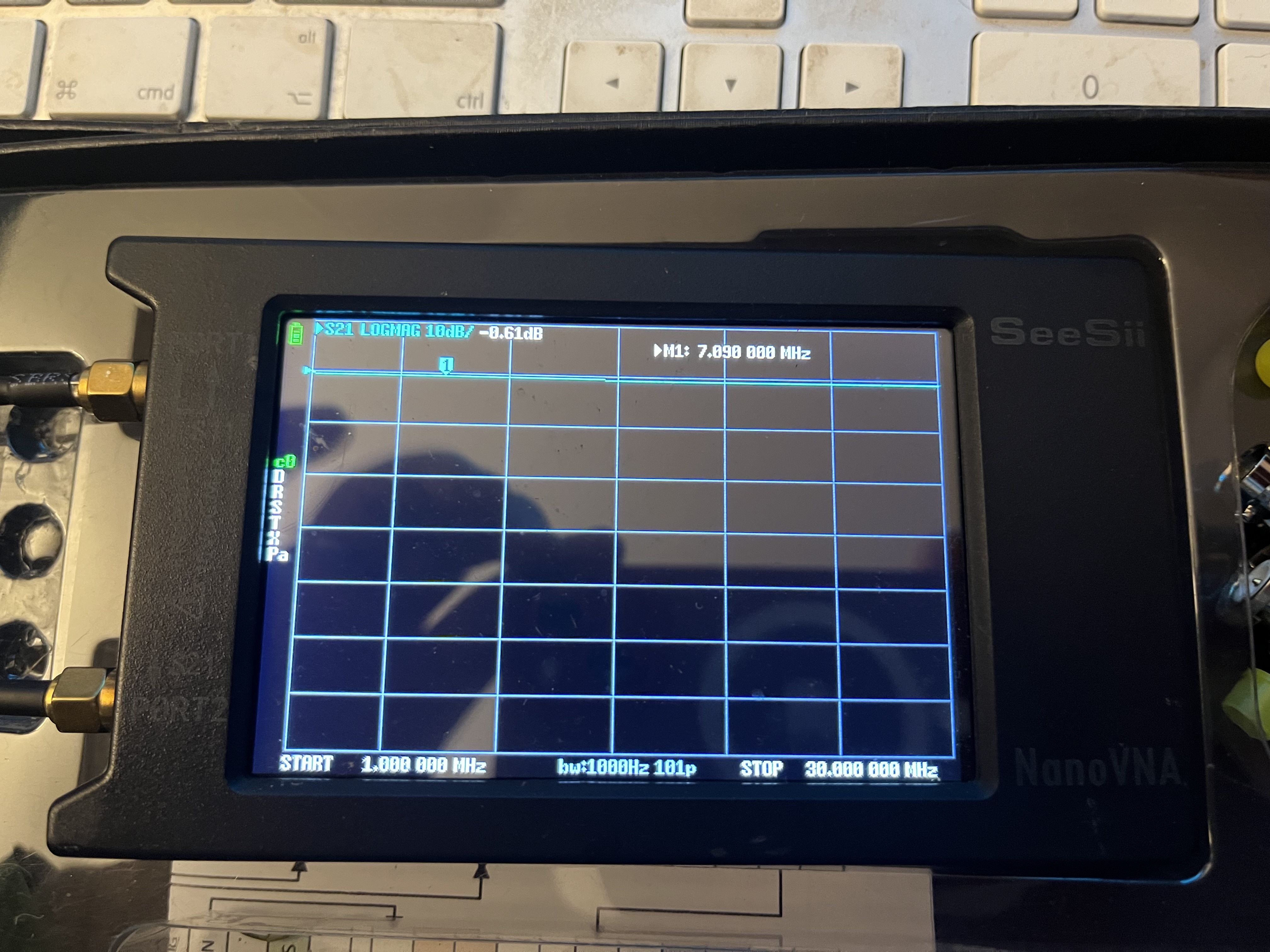
In recent years, many hams have bought a budget Vector Network Analyser (VNA). From the outset, this can readily be used as a (portable) VSWR meter for checking antennas.

Q: “How many people use their VNA for anything more than this?”

A: “Listening on the bands, browsing reflectors and using other anecdotal sources, not many.”

If a VNA is used solely a 21st-century VSWR bridge, then perhaps my 40-year old OskerBlock (see eHam etc) still has a role to play. It can check VSWR in an instant - no SOL calibration required - and monitors proceedings throughout the QSO; though you wouldn’t want to be lugging it up to a SOTA summit. But presumably most SOTA antenna trimming is done in the back garden or local park?


A little maths:

Q1: If x^2 = 4, what is the value of x? (x^2 means x squared)

Almost everyone shouts 2 which is correct, but -2 (MINUS 2) is equally valid.

Q2: If x^2 = -4 (MINUS 4), what is the value of x?

More of a pause? My dentist, who has a good scientific education and a Uni degree, didn’t know. Inflicting pain can be a 2-way street :slight_smile:

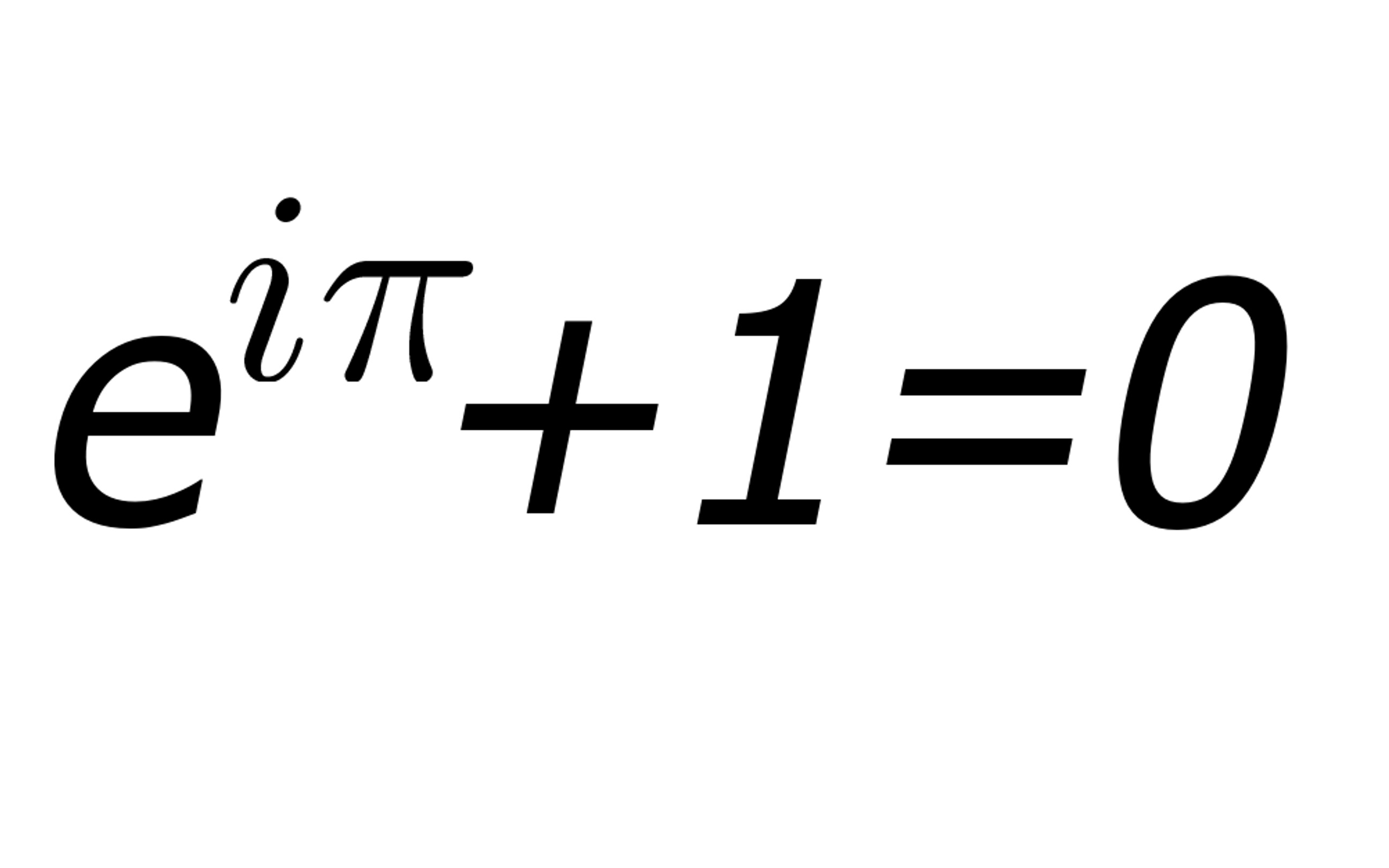
The answer is: x = +2j OR x = -2j where j is the SQUARE ROOT of -1 (MINUS 1).

For many, this should be familiar ground. For others, it may be something of a shock.

A number of the form: A + Bj is known as a COMPLEX number. A and B themselves are REAL numbers: 1.372, -50.64 etc.

In the UK, for 16/17 year old students, only the English FURTHER MATHS A-level syllabus appears to cover COMPLEX numbers. Otherwise you are likely to need Wikipedia, or year 1 of a Maths/Physics/Engineering Uni degree course.

The ARRL Handbook has a useful, but brief, summary of COMPLEX numbers. There’s no explanation I can find in any of my RSGB publications, but the search has not been exhaustive.


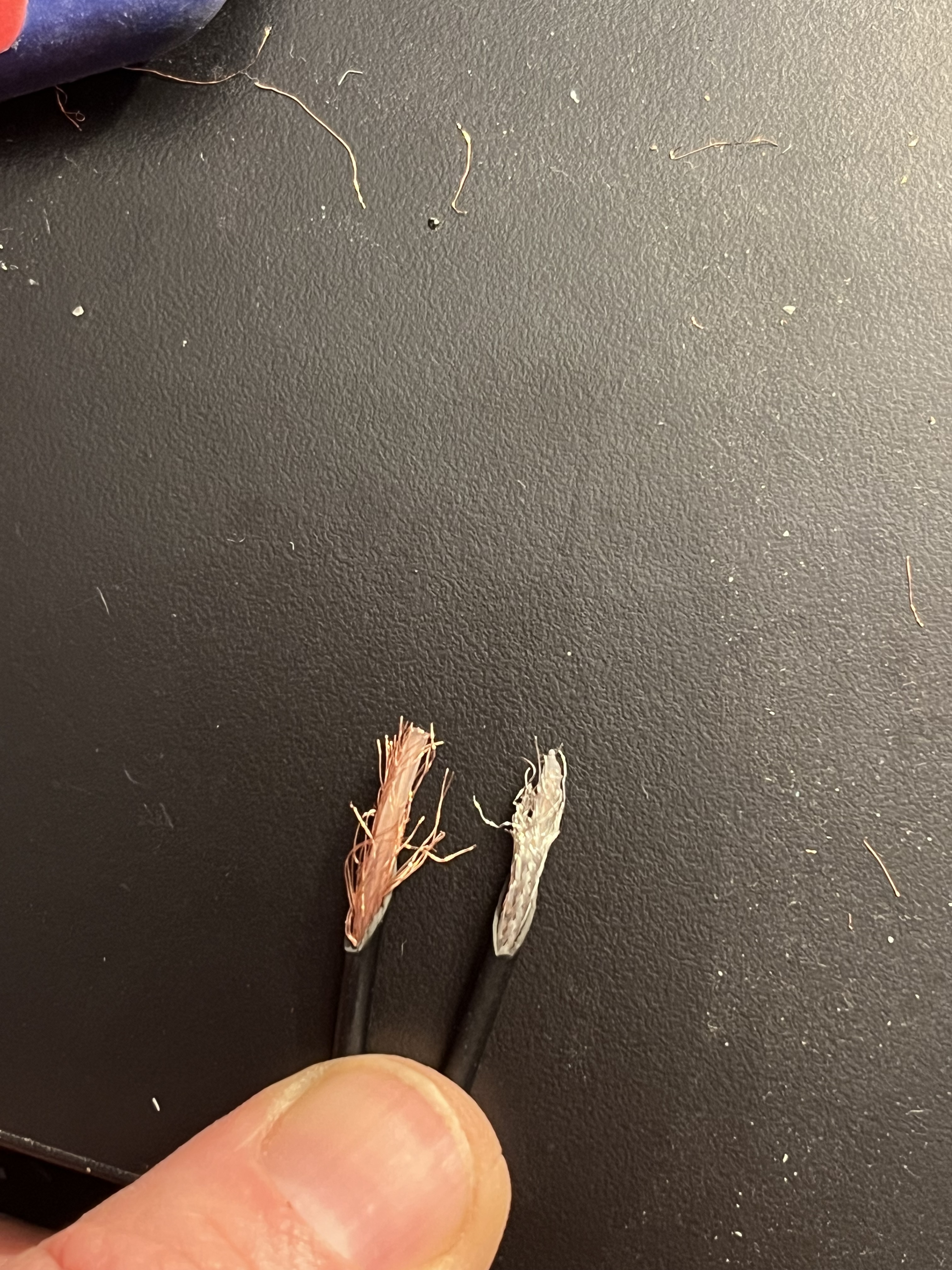
Checking your new dipole for resonance on 14060kHz, the VNA may tell you it has an impedance of say 45.6 + 18.6j. The ‘+18.6j’ part represents an INDUCTIVE reactance; the antenna is too long, and you need to trim a bit off.

If the impedance was say 48.3 - 15.9j, the ‘-15.9j’ part represents a CAPACITIVE reactance; the antenna is a bit too short, you need to ‘unfold’ some of the wire you folded back at the ends of the antenna. The less-experienced have a small soldering job.

Hopefully, for almost everyone, I am ‘teaching my grandmother to suck eggs’. Not sure of all the international equivalents for this English expression, it means: ‘telling someone in detail about something they already know well’.

Understanding COMPLEX numbers shines light on the myriad uses of your VNA, and can provide many ‘… now I understand’ moments in ham radio and electronics.

73
Dave GM4EVS

11 Likes

I can confirm that, and still remember that, despite abandoning engineering on completion of my B.Eng hons. I dont, however, remember how to bias a transistor.

2 Likes

Give it a promotion without any resistance?

4 Likes

Neither do any of the CB amplifier makers.

3 Likes

It isn’t so much knowing how to use complex numbers, as we have various calculators available that will handle them, but knowing what NOT to do.

For example, you can’t take an impedance like 40 + j30 ohms and combine the two terms into a single number without losing information. Sure, the square root of the sum of the squares gives you 50 ohms, and in AC power work this is often called “impedance”, but that isn’t going to get you a 1 : 1 SWR in a 50 ohm system. (It will be 3 : 1 instead, if you want to check your math.)
That isn’t the “impedance”, but the “magnitude of impedance”, and, without the corresponding phase angle, it isn’t the whole story. In fact, I’m of the opinion that the |Z| readout should be removed from most such devices, as it only causes confusion.

Looking at the complex impedance value, rather than just SWR, enables you to do a lot more things with such a device, such as measuring coax loss, or determining the resonant frequency of traps. (If trying to tune an antenna to resonance, where X = 0, make sure you account for the length of the coax cable, or you can be led far astray.)

But there is more that you can do with a VNA that a single-port Antenna Analyzer won’t do. For example, connect a coax cable, filter, transformer, etc. between the two ports and measure the loss vs. frequency directly. With enough resolution, the circuit under test might consist of coax to two antennas, allowing you to swap out the antenna at one end with another to measure relative gain.

That’s not to say that such devices aren’t good for plotting impedance, or just SWR, across frequency for tuning antennas. But they can do a lot more.

2 Likes

Ham radio is a ‘large tent’. Over the years, I have come to realise that my interests often have little overlap with those of others.

Out there are hams skilled at playing musical instruments, painting (pictures, not kitchens), speaking foreign languages and so forth.

For me, though maths and electronics are lots of fun, on a scale of 0 to 10 my Stratocaster skills are about 1.0 X 10^-27.

@WB6BYU makes several important points. As a measuring device with ‘2-port’ capabilities, the VNA can report on the frequency response of many ‘2-port’ items including coax cable, filters and amplifiers.

For more, Wikipedia covers topics such as Two-port networks, the Smith Chart and Scattering (S) parameters. But, as you know, YouTube typically has a wider spread of educational material.

Of course, right now you may be far more interested in driving up your SOTA score, or improving your rendition of Bruch’s Violin Concerto No 1.

‘Beauty is in the eye of the beholder.’

73
Dave GM4EVS

3 Likes

Today I used my NanoVNA to look at return losses in my coax….

It’s a salutary tale of the results of poor quality cable and connectors sourced via a major online Chinese retailer……

I should be able to hear you all a bit better now……

RG174 high quality cable and connectors from a major SOTA specialist in the UK, -0.61db loss on 7.090Mhz:

Used RG174 cable and connectors sourced from a major Chinese discount online retailer…. -22dB loss at 7.090Mhz.

Certainly I now don’t why this is named after a Genie and its also defiantly not ‘express’.

2 Likes

Interesting! I wonder why there is a dip at around 2MHz? Have you cut into any of it to see what the conductors are like?

Dave,

That’s a very interesting post and I agree with your points made.

One aspect of complex numbers I find very useful is the graphical representation where the real numbers are magnitudes on the left and right sides of the complex plane, and the points that are not on that line represent complex numbers.

I recall one teacher explaining that complex numbers are a representation of points on a plane where moving away from the horizontal line of real numbers is a way of dealing with the 90 degree phase shift of inductors and capacitors. There aren’t really complex numbers, there is no square root of -1, but what if we represent phase shifts and impedance points on a plane where moving away from the horizontal or x axis means there is a 90 degree phase shift. What if we adopt a convention that operator j represents the sq root of -1, then what happens. That concept changes how you view this esoteric field. Apply a 90 degree phase shift twice (the equivalent of j**2) and what do you get, a reversal of direction, or -1.

The complex number arithmetic is just a mechanism to allow us to use what looks like ordinary arithmetic to manipulate concepts like 30 + j20 as if the arithmetic was valid. Turns out to be true, if you treat j (or i in maths) as representing a phase shift of 90 degrees in that complex number plane, the maths rules we already learned do work. Remarkably, with one change to normal arithmetic, accepting that an operator j means the square root of -1 makes it possible to do arithmetic with complex numbers. The rest is left as an exercise for the student…. A piece of maths humour and cruelty.

My maths teacher in high school was VK1KM at the time. Quite a few good insights he gave us.

Andrew VK1DA/VK2DA

4 Likes

Yes there are!

It’s i.

It’s totally valid.

Complex numbers were first conceived of in the 16th century for solutions of cubic equations. I think it took a couple of hundred years for them to be widely accepted by mathematicians. This is all before the discovery of electricity and their use in reactance.

3 Likes

Andrew

Your memory serves you well. A complex number can be represented GEOMETRICALLY as point in a plane, using an x-axis and a y-axis at right-angles.

For complex numbers of the form A + Bj, the x-axis represents the values of the A component (the so-called real part) and the y-axis represents the values of the B component (the so-called imaginary part). For a given complex number, using the A and B values as coordinates (much like Lat & Long) gives a single point P in the plane.

This structure is known as an ARGAND diagram. Googling provides as much info as you want.

Having plotted your point P, the length of the straight line from the origin O (0,0) out to point P gives the MAGNITUDE R of the complex number. The angle measured from the positive x-axis, going counter-clockwise round to the line OP, gives the PHASE ANGLE Ɵ of the complex number.

We have now seen how a complex number can be represented in two interchangeable ways:

1 CARTESIAN form: A + Bj

2 POLAR form: Magnitude R, and phase Ɵ (theta)

Depending on the task in hand, one form is often more helpful than the other.

Enough for one day :slight_smile:

73
Dave GM4EVS

3 Likes

Here’s the most beautiful equation in maths.


It’s beautiful because it relates two irrational transcendental numbers with an imaginary number and the additive and multiplicative identities.

2 Likes

Here you go ! Guess which is which……

Poor quality is very fine strands poor density outer, without a weave as far as I can tell.

1 Like

I still want to know how that Chinese cable managed 22dB of gain. That would sure improve my QRP signal!

(-22 dB of loss = +22 dB of gain)

1 Like

Tim,

22 dB of loss is almost certainly a connector assembly problem. You need a very very long piece of thin coax to get that loss at 7 MHz. Or an open circuit shield connection. Or a centre pin not connecting due to faulty assembly.

Please check. Those El cheapo connectors might not be as bad as you say. I don’t believe they could make them so badly.

I do believe it is possible to assemble them with an open circuit on the centre pin when mated or with a braid that has come adrift.

Are they crimped or soldered,?

Did you do an ohmmeter check on continuity and shorts? (Check cable by itself and when mated).

73
Ron
VK3AFW

2 Likes

With that one post Richard it’s 1979/80 again and I am studying for my A-level Pure Maths! I remember when we were introduced to it being astounded at how much was all linked in that one expression. It was the same we were introduced to the term cis θ. I shall go and see if I still have any A level maths books lurking still after we had the big clearout of old paperback novels and books to the charity shop.

It’s well known that Chineesium SMA/BNC/N connectors can be somewhat lacking compared to the full price Suhner / Radiall / Amphenol etc. Whilst SMA may be designed for use up 12.5GHz you do need to check if the actual connector used works at such frequencies. Whether it’s cheap or full price.

From experience, Chineesium RF connectors are fine at low powers (100W) and HF frequencies. You need to be more careful for VHF/UHF and if you up the power. It’s really only above 1.2GHz and at higher powers you see the shortfall in the design and manufacture.

So the cheap ones from eBay are fine when targetted at the correct application. Otherwise it’s get your wallet out and open it wide for the good stuff :wink:

That trace shows the loss decreasing as frequency rises, i.e. high pass filter which is interesting. There’s some interesting L&C in that cable!

They are crimped. One of the initial checks was for continuity and shorts. Defo no short but slightly higher resistance than my other wires in checking continuity.

Because the connectors are crimped, it’s very difficult to take apart. I’d like to cut the connectors off, short an end with both connectors and the wire. Then check for continuity and return losses. That way, I can narrow down the culprit area. Will report back.

This cable has been used for many SOTA activations. It’s really obvious the woven sheath is very poor quality and that’s my guess. It is not woven, very thin strands and very low density of strands . Certainly would not pass a decent bend or stress test ! Combine that with the abuse that I put my equipment through……

Indeed - very interesting!

Tim

1 Like

@MM0FMF a bit more maths - see below.

73
Dave GM4EVS

Thin steel centre conductor maybe?

If the cable characteristic impedance is not 50 ohm, that would affect the attenuation measurement. What does it look like if you terminate one end in 50 ohm, and look at the other end with the VNA?

Mind you, it might be better to just bin it and move on!

1 Like