I don’t want to say I suggested so… but all of a sudden those suggestions about using poncy cables and whether there are marginal gains become a lot more to the point. If you buy LMR-100 and treat it well it will massively outperform Chineesium cable like this RG-174 example.
Your cable might be of poor quality, but -22dB is a sign of a damaged cable/connector. I would say crimped cables are not very durable because repeated twisting causes the metal crimp to cut the braid strands.
Personally, I use Amphenol clamp/screw connectors, and they work very well for me. Since they also clamp the plastic sheathing, repeated twisting is less of an issue.
Agree, very few!
To be honest not many hams tune filters, test the gain of amplifiers or cut stubs.
However 100% of the people reading this post have coax!
@G5OLD Showed us how to do a 2 port measurement S21 cable loss measurement, very quickly finding out he had a junk cable. Very handy, but limited to the shack where you have both ends of the coax next to you… What if one end was 60m up a tower?
Its very easy
You need a VNA or Antenna Analyser where you can perform OSL calibration
You can make the Open and Short easily, but best buy a used 50 ohm precision load (like a Suhner etc)
Learn to work in Return Loss, same as SWR but much easier to work with!
Do a Return Loss (RL) sweep, with the far end of the coax open or short.
Cable loss in dB (IL) = RL/2
Stick your precision 50 ohm load on the far end, RL sweep again and you will see nice RL > 20dB if your coax is good.
The signal from your analyser travels along your coax, with loss occurring as it goes. It hits the end and there is a 100% reflection (open or short). The reflected signal travels back along your coax, again with loss occurring as it goes. That’s why IL = RL/2..
All you need is a single port device like the Rigexpert AA zoom series, these also have a decent Distance to Fault function. Various other VNA’s will do this as well.
When your comfortable with this, start to explore DTF & TDR. Then you really do have more than a portable VSWR meter.
73 Gavin
GM0GAV
PS if this sends any UK readers off looking for a N Type precision load, PM me. I have a few rescued from disposal a few years ago.
That may be a useful estimate in many cases, but the accuracy is better if you measure the return loss under both conditions (far end open and shorted) and average the two readings.
The reason is that coax loss in a mis-matched line is not linear with length. Most of the losses up through the VHF range are due to the resistance of the conductors, and that will be highest at the points of highest current. A discussion by Owen Duffy is here: Estimating Matched Line Loss from Return Loss.
I ran into a particular problem measuring the loss of a piece of RG-174 that I had used in my backpack dipole kit for many years. The antenna end had never been properly sealed, and there was some corrosion in the braid. (It still works well enough for the purpose, but I’m in the process of replacing it.) The cable was about 1/4 wavelength on 40m.
When measuring return loss with the far end open, current was minimum in the corroded braid, so the losses were lower. When measuring with the far end shorted, that section of the coax was at maximum current, so losses were higher in the piece as a whole. (There was also a matter of trying to get a good short circuit, as the connection hardware had corroded a bit over the year as well. But I finally did after a bit of polishing.)
As a result, I now check line loss using this method, based on the resistive component at the frequencies where the impedance is low (far end open or shorted as needed). It doesn’t give you as nice of a plot vs. frequency, but does well enough with an accurate antenna analyzer. With a VNA, of course, you can use both ports and get a better measurement.
For some decades, the ARRL (Antenna) Handbook has published a useful amount of Transmission Line theory, Smith Chart basics and associated equations.
For day-to-day operating, most hams need to know very little of this. They can fill their logbooks with world-wide S2S qsos etc, oblivious to the physics behind the deployed 5-10 metre ‘black snake’.
However, inquisitive ‘maths and physics’ folk discover that the theory of transmission lines actually extends to the depth of the Mariana trench.
To understand all this, requires notable tenacity together with quite a lot of Uni-level maths. Not a well-trodden path within the ham community.
Over the years, the ARRL technical journal, QEX, has ably-covered quite a lot of the ground.
One of the current protagonists is Steve Stearns, K6OIK. His many papers can be found at the link below.
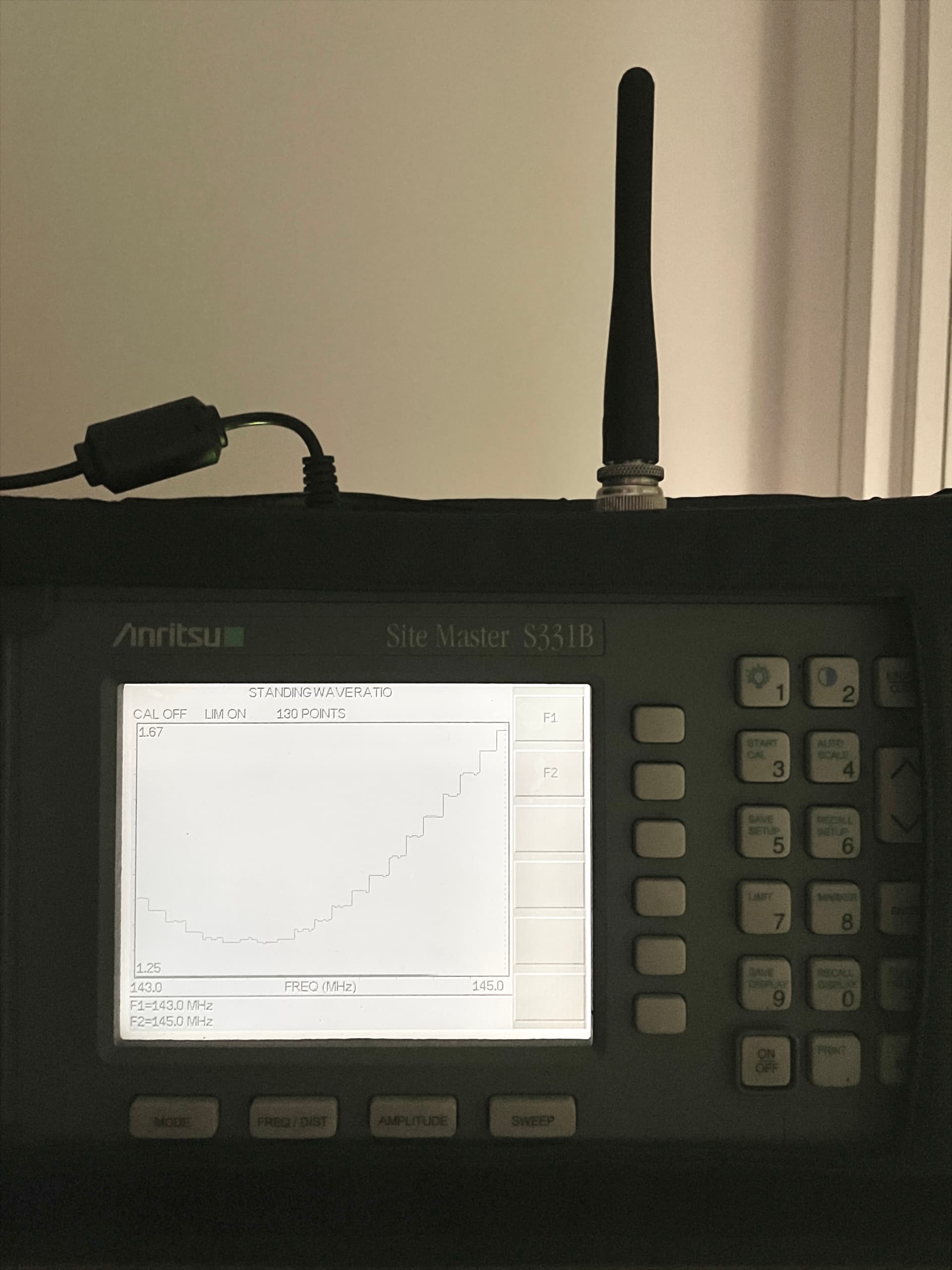
Recently I’ve got my hands on a fairly old Anritsu S331B Sitemaster industrial measuring set. It can do SWR, return loss, power measurements in a range of 25-3300 MHz Considering the device is an industry standard tool there are no issues with accuracy. It can also be calibrated before each measurement on open/short/load.
Some great device I must admit. Unfortunatelly it can’t go below 25 MHz I’d say VNA should be something similar although WAY cheaper, worth an investment I suppose.
Yes your correct, I should have said when we did it professionally on an older Sitemaster type VNA without specific cable loss function you should use a wide frequency range sweep & average the graph. Then you get pretty accurate result.
I believe the RigExpert AA’s cable loss function requires you to sweep with both an open and short. The modern R&S ZVH has a single port cable loss function only requiring an open, that will be using a wide sweep and averaging.