Added afterwards. I ordered it, came with instructions which I followed.
Initially though it was the connectors to board shorting, and they are now soldered in with heat shrink.
Elecraft admitted it was a problem….
Added afterwards. I ordered it, came with instructions which I followed.
Initially though it was the connectors to board shorting, and they are now soldered in with heat shrink.
Elecraft admitted it was a problem….
Thanks, I’ll take a good look at it.
Just wondering, once you have the board installed would it show as an option in the menu system like other add-on boards do?
I’m assuming not, unless you customised the firmware, which Elecraft wouldn’t be pleased about (maybe they might offer to help?).
Thanks! Yes, one must be careful to trim those fairly close to the board after soldering, also with the KXUSBC2. It’s easy to do and then there’s plenty of clearance, but we need to add a reminder about this to the user guide.
The KX2 firmware does not detect whether options are installed or not. You simply set the menu option for KXIBC2 to “nor”, and then the features enabled by that (RTC and battery voltage display) will also work with the KXUSBC2.
It seems like the KX3 is ripe for a similar board to the KXUSBC2 using the 3D-printed tray that N6MTB has since there’s still side panel space for a USB socket to poke through. Or maybe leave enough space for the USB plug to poke into, requiring a bigger hole in the KX3 non-RF side panel. Throw some USB-UART in there; the scope creep could be endless!
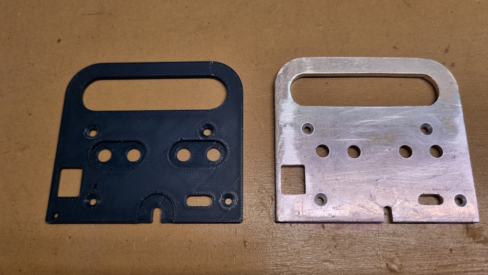
Thanks. I printed it out and used it as a template to make an aluminium end plate. It’s a bit rough but should fit well for testing. The area around the 3.5mm jacks still needs to be milled out.
Does the KX2 require metallic side panels ? Or could we consider ABS or ASA printed replacements ? Maybe even Nylon-CF if I’m feeling exotic.
Just a thought…… that probally needs to be shot down ? Could well play a conductive or RF role
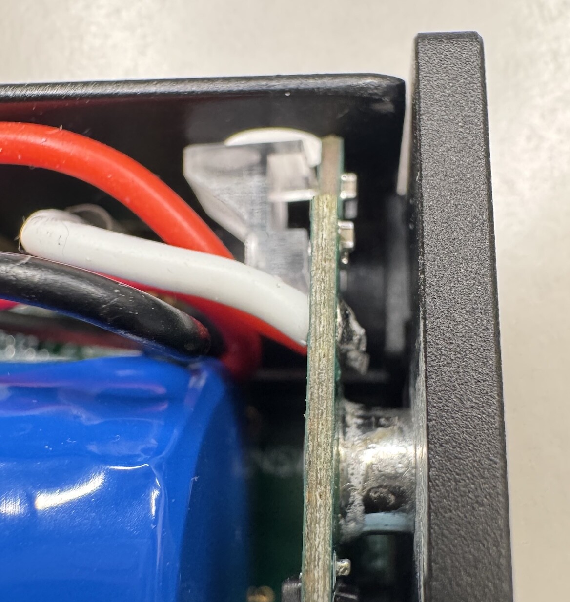
The right side panel serves as the heat sink for the PA transistors. The left panel doesn’t seem to have cooling duties, but helps with shielding. The original panel has the black coating stripped in those areas where the panel makes contact with the chassis, and the same should be done on the KXUSBC2 replacement side panel – especially given that there is only one ground pin on the headers that the KXUSBC2 connects to, so the additional grounding via the panel is pretty much necessary.
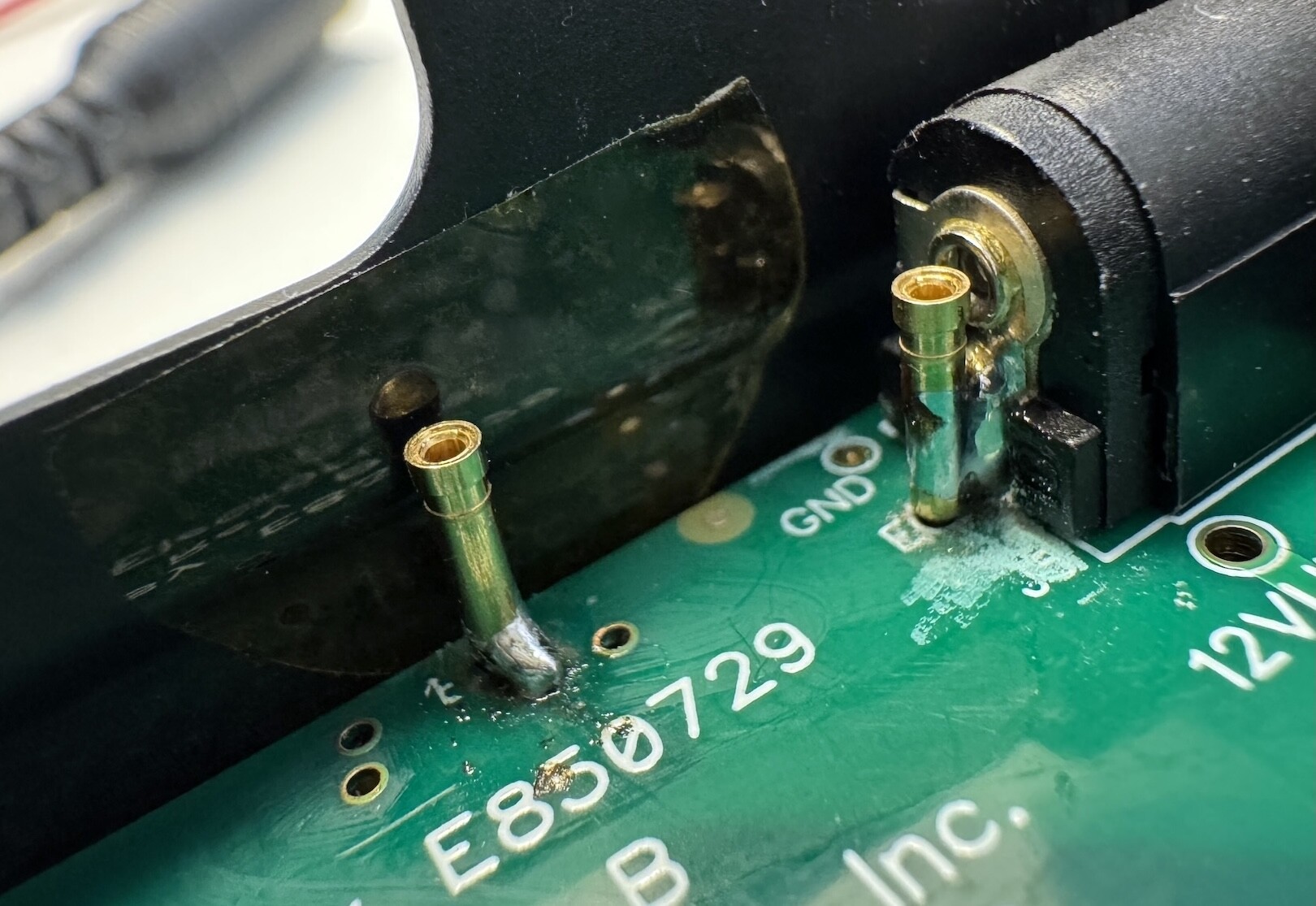
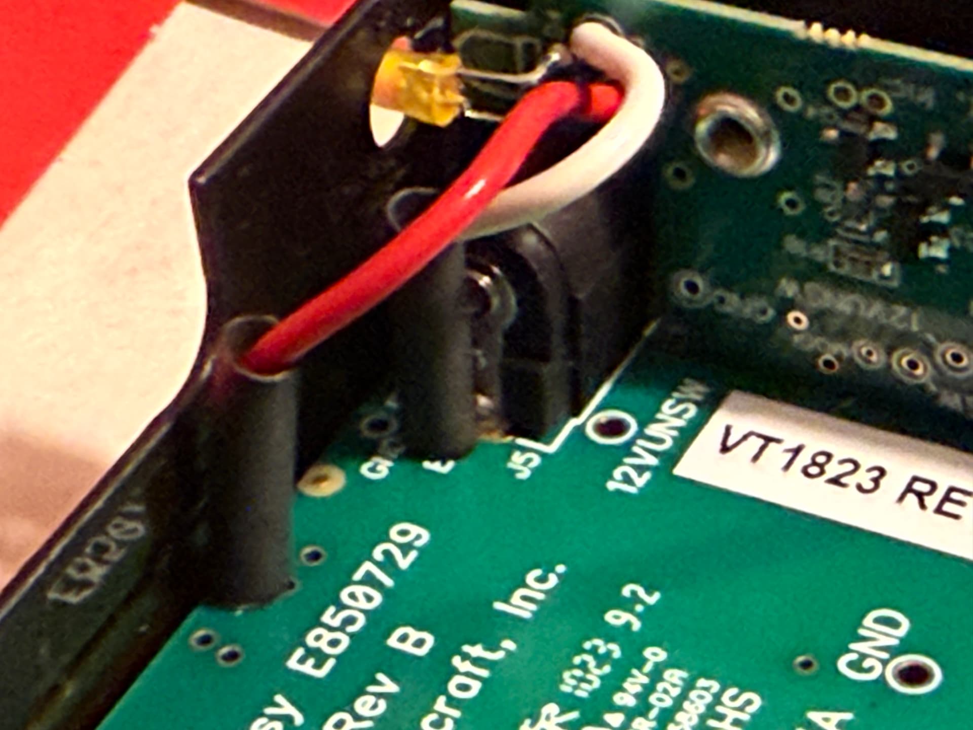
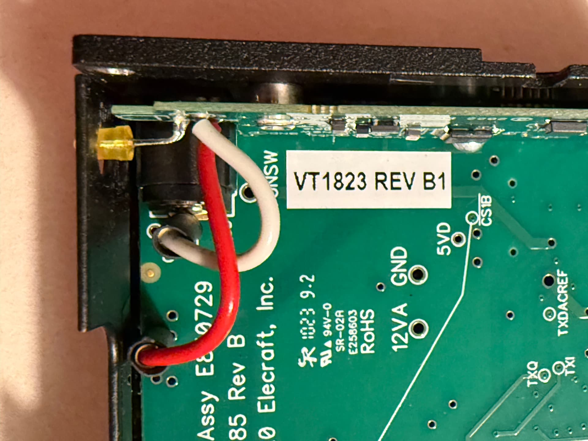
It seems that the pin receptacles for the battery/external connection are now pre-installed on new KX2 transceivers, even if ordered without the KXIBC2 option. That’s good news for (new) KX2 owners, as it means a KXUSBC2 installation is possible without soldering ![]()
I’m not sure what to think of the soldering job done at the Elecraft factory though (photo of a brand new KX2 unboxed today)…
I’ve seen better ![]()
I know I answered the poll, but I have another African adventure planned for next year (2026) and this would solve one logistics issue if I can get visiting licence sorted and radio gear on board!
It took me a while, my memory tricked me and my factory installed KXIBC2 is wired identically. Same kind of unshrunk heatshrink sleeves, same tolerances.
Status update: Nine beta testers on three continents have received a KXUSBC2 (rev1/2). Seven have already got it to work on first try, and feedback from the other two is pending ![]()
During testing, a minor issue with the alignment of the standoffs/screw holes on certain (not all) KX2 has come up. I have modified the PCB geometry in an effort to solve this issue. Aside from that, no problems with the electronics or the firmware have been found. Looks like we’re getting close to production readiness!
Production files for board rev3 are now in the repository, and I have ordered another 10 pcs., mostly to confirm that the alignment issue is resolved. I’ll keep you posted.
It would be great to have a handful of distributors located in different parts of the world, who would be willing and able to order assembled PCBs from a PCB factory and side panels from a CNC shop, solder the standoffs, flash the firmware, and sell them along with the necessary auxiliary parts/wires. One shop from the UK has already expressed interest.
It could also be a community effort, where a knowledgable member of a local community/association places a PCB/CNC/parts order for the other members. Of course one could also order the PCB and side panel for oneself, but PCB production with qty. 1 does not make much economic sense.
As far as I’m concerned, I don’t intend to make any money from this project, and I also don’t want to become an electronics distributor (Switzerland is not a good base for shipping stuff around the world anyway, due to high postage rates and customs issues due to non-EU etc.).
73, Manuel HB9DQM
Pre-order List:
![]()
rev3 boards have arrived, and everything is fine. Although feedback from two of the nine rev2 beta testers is still pending, I think it’s safe to say: The design is complete! ![]()
![]()
Neil @G7UFO has started taking pre-orders for the KXUSBC2 in his online shop while he’s awaiting delivery of the boards and side panels from the factory. Perhaps amateur radio related shops in other parts of the world also want to offer the kit – contact me if you are interested.
Another option (for people who have some experience ordering and working with PCBs) would be to do group buys of the boards and accessory parts, e.g. within a club/association. All information required to do this can be found in the hardware documentation.
In the meantime, here is a short video showcasing two KX2 charging each other ![]()
It also demonstrates how pressing the recessed button triggers a PD role swap, reversing the charging direction. One KX2’s battery is already almost fully charged; therefore, the power is lower in that direction (taper charge). I don’t know if this will ever be useful, but it’s cool to see that it works ![]()

I’d like to pre-order this but excuse my ignorance, I am unsure what spec to order with the different options available. What exactly do I need to check for in my KX2 to ensure I get the right one?
Thanks again for all the great work with this, and to the testers too. I look forward to adding one to my KX2.
EDIT: Ah I read through there. My KX2 doesn’t have the pins on it. This looks pretty hardcore to solder those pins in. Dunno if I am brave enough to tackle this one.
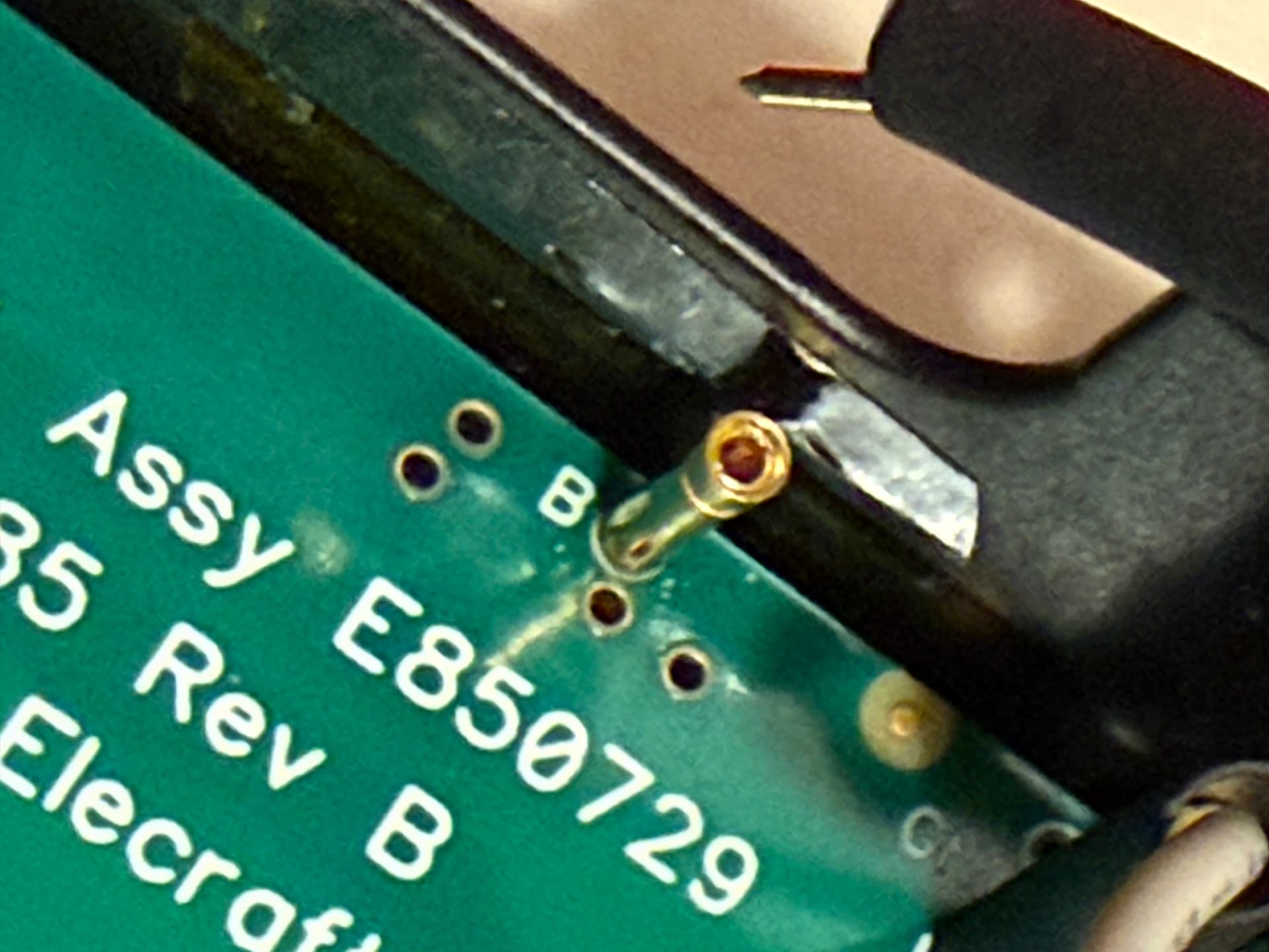
The difficult one is 'E’ as the hole it would fit through is likely filled already. As in @HB9DQM image above, Elecraft seem just to be soldering that to the barrel connector. The B pin is just a place and solder job.
I’ve also added a bit of extra text to the page to explain which options should be selected based on a how your KX2 is setup currently.
… perhaps someone (like me) would be very, very happy to have just the convenient charging option (standard/fast) via the KX2’s regular DC power jack, hi.
Seriously, Manuel/Neil: Does the KXUSBC2 board work perfectly fine even without the USB-C port (and the functionality based on it)?
Thanks for adding that. It made things much easier when comparing the notes on the page with my KX2 set out in front of me. In hindsight it is all captain obvious stuff I know, but initially I wasn’t 100% sure what needed to be looked for to make the right purchase configuration.
Had a look at my KX2 there. It’s an earlier model - low serial - and doesn’t have the pins in it or internal charging board. It looks like a fairly simple install for the most part, but the pin soldering worries me a little as knowing my luck I’d end up wrecking the transceiver. Might just wait and see how folks get on first and then jump in.
Wonderful stuff though all the same and a great result that boards are now entering the final phase before being available to everyone who wants them. Kudos to all involved.