Yes, of course that’s implemented too - and so is the voltage display. ![]()
4 Likes
Thanks for the video, Fraser! Seeing you solder in those pins like it’s child’s play should make people less nervous about the process ![]()
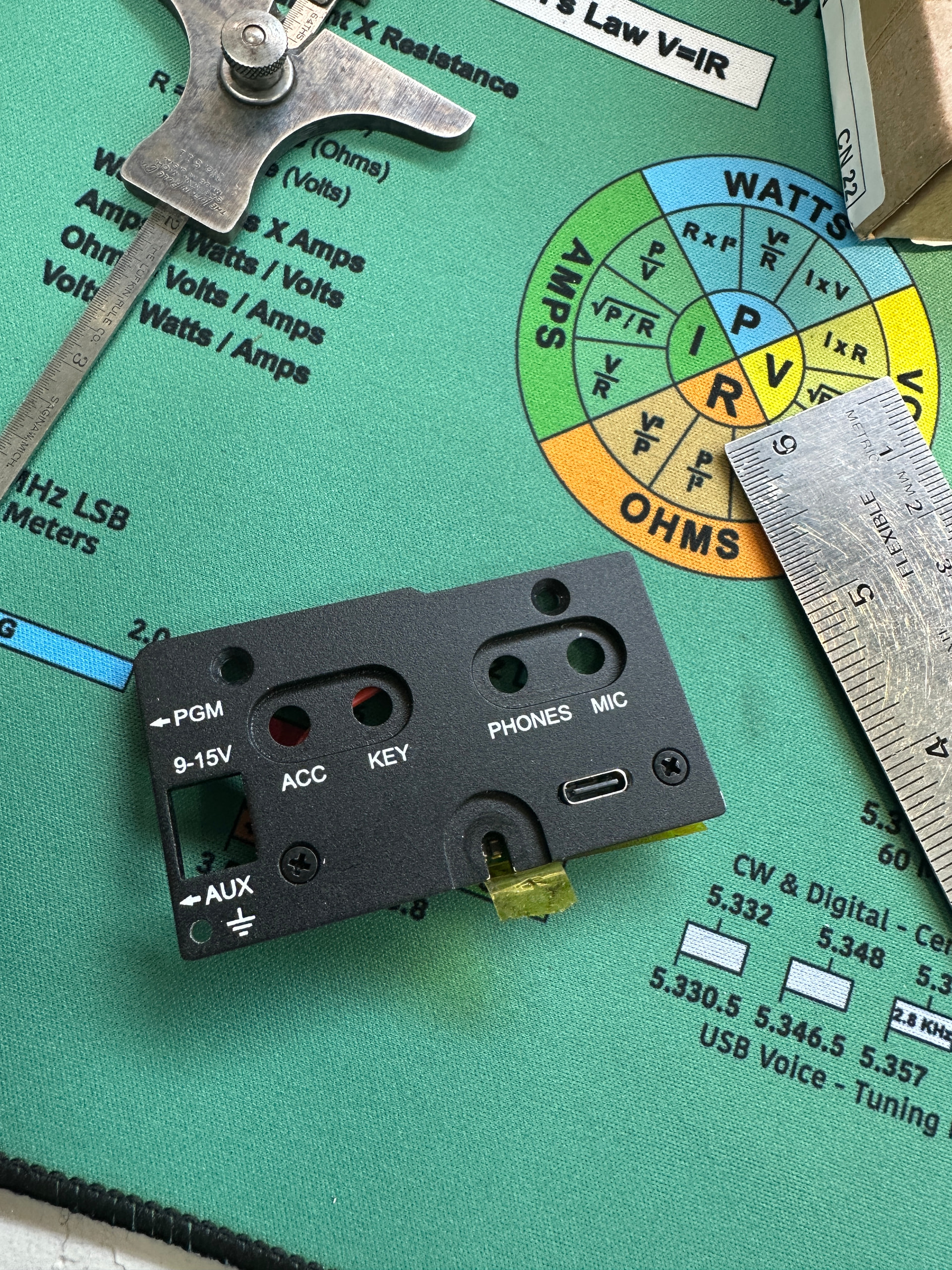
I’d also like to highlight the excellent job that Neil @G7UFO has done to make the kit available at a very high quality (lasered side panel, wow, makes my Dremel work look barbaric!), and at a very fair price given that he prepares everything for you – panel, standoffs, wires, tape, firmware.
8 Likes
Thanks again for the video, as I mentioned I did have a go at putting one together but after my “first take” which included a screw flying into a box at the other side of the room, my hands obscuring everything in the video and some pretty inventive cursing, I realised my time would be better spent fulfilling orders ![]()
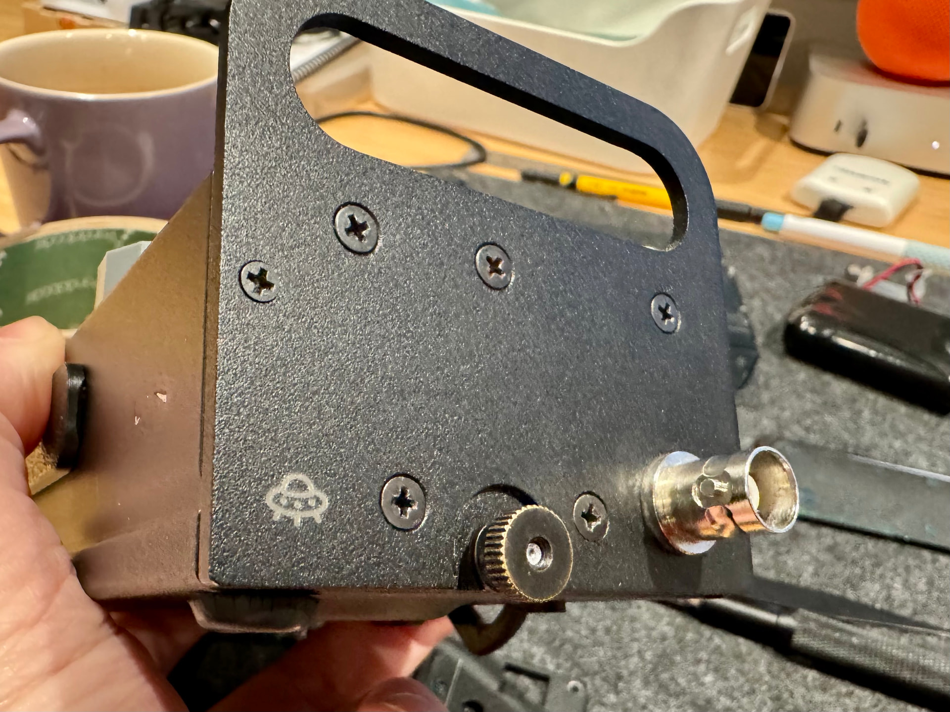
As my dad (M0BAR) noted, if its not tied down in your house, it’s getting lasered ![]() . I even gave my KX2 a tattoo:
. I even gave my KX2 a tattoo:
6 Likes
Brilliant! I thought it was a special Elecraft clock board you need to get separately for some reason. Do you have to enable it in the menu or does it just work by default?
It’s what got me off the fence. Looks like Fraser simply stuck the pins in to their thru-holes and gave a little dab of flux and solder to each to secure them? What temperature was the iron set at and is it just a quick ‘dab and run’ job or do you need to leave the iron there a fair while to heat up the PCB solder pad around the pin? Assuming it’s a dab and run?
Hot enough to melt the solder in use. The temperature will vary depending on the type of solder you are using. Old style 60:40 Lead solder needs a lower temp than modern Lead-free solder.
With the greatest of respect Ian, if you are asking these questions then you probably need more experiance and practice soldering before you attack a £1600 radio’s internals. Soldering is not difficult, it comes with practice and the use of quality solder. Nice soldering irons etc. make the job easier. I’d suggest building some cheap kits (don’t have to be radio related) from eBay etc. first. Or find a local ham with plenty of experience of knowing which end of the iron gets hot and do the job at their QTH under their watchful eyes and tutelage.
4 Likes
See KX2 Owner’s Manual, p.23, Special VFO B Displays
2 Likes
You just need to set the KXIBC2 setting to “NOR” to enable it. You may have to upgrade the KX2 firmware in order to get that setting.
The difficulty also depends a bit on which particular version of the RF PCB you’ve got. For example, on my friend @HB9HNT’s KX2, the annular rings (remaining copper around the holes) were very thin, making it tricky to get the solder to flow onto them. On Fraser’s KX2, the pads look more decently sized.
In any case, enough heat is the key – preheat with hot air, and/or use a powerful enough soldering iron with a relatively large tip. I used 380 °C for lead-free solder. Some additional flux also helps.
No need to be too nervous about it – it’s not that difficult, and you’re very unlikely to really break your KX2 in the process. Even if you completely wrecked the B and E pads, the KX2 would still work fine, and you have a second chance at installing the KXUSBC2 too (there are two B pads next to each other, and instead of using the E pad, you can also solder directly to the DC jack’s center pin).
Just look at the soldering job that Elecraft did on my new KX2, and tell yourself: “I can do better than that!” ![]()
3 Likes
Spot on. That’s noted for the install.
Thanks everyone as well for all the input too, appreciated. ![]()
Good stuff. I think mine is on the latest and I only checked recently too for something else so should be okay.
2 Likes
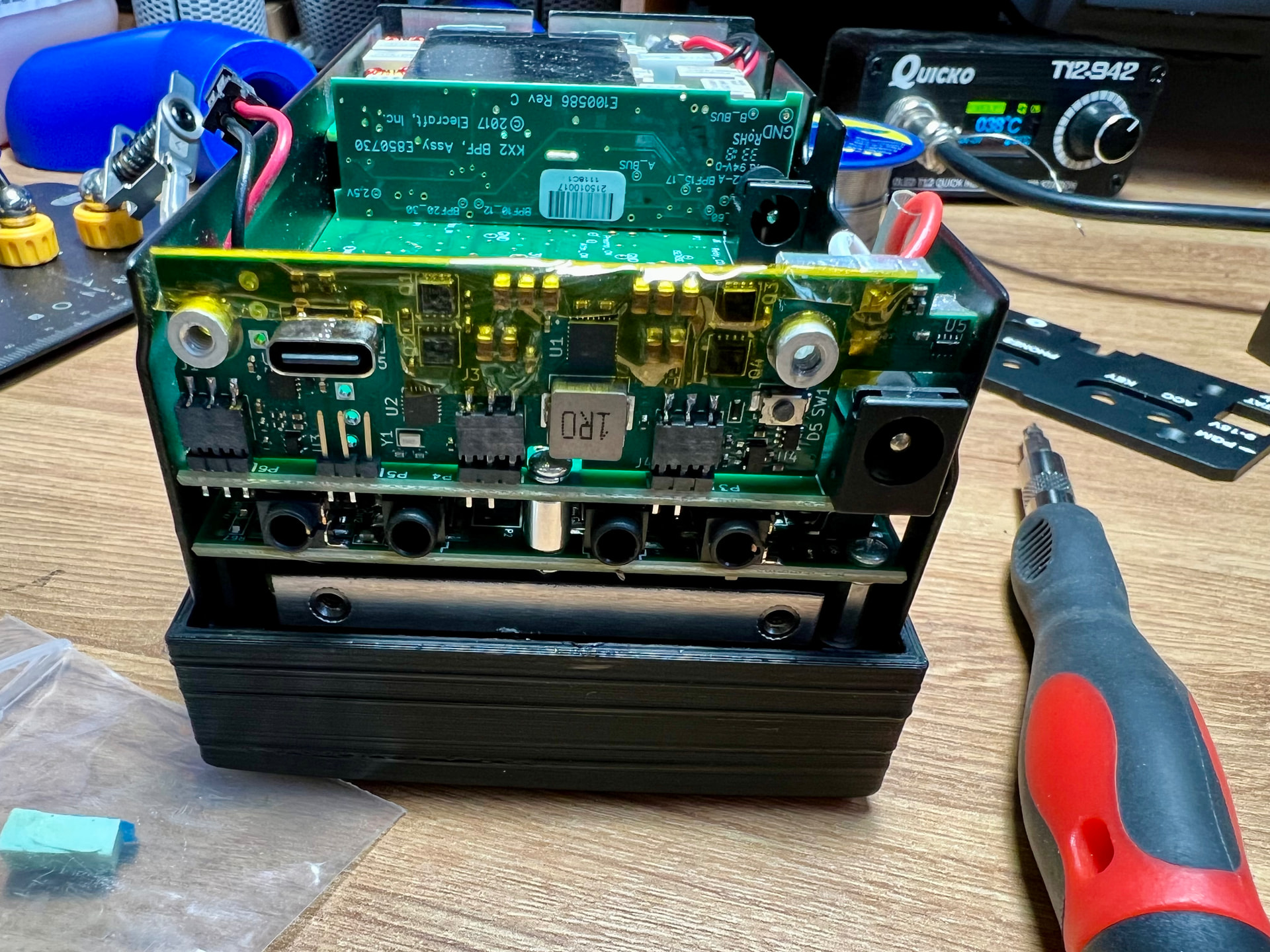
The board arrived on Friday from G7UFO. (Great service Neil!) and I installed it today. It went together with no issues. I removed the main board to install the sockets.
I also milled a slot in the side panel for the USB connector. I forgot to drill a hole for the configuration pb Will do that another day.
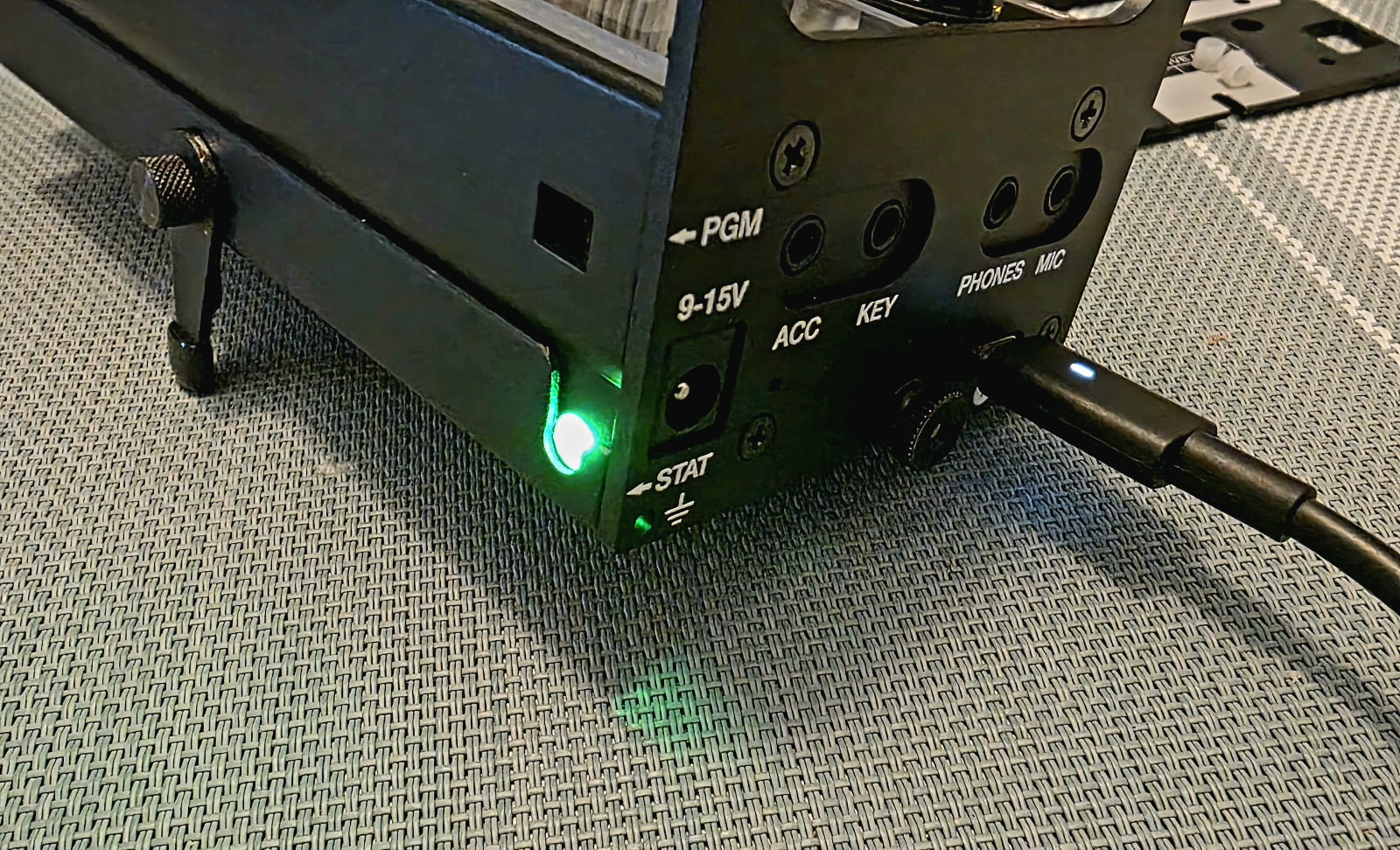
Charged the KX2 successfully and did a POTA this afternoon. No issues with the board. Kudos to Manuel for a very comprehensive and professional design.
It will be great to charge via USB-C and not have to remove the battery.
9 Likes
Fantastic work there Rick - very clean job.
My second video on the subject covers a couple of upgrades that @G7UFO Neil has rolled out, as well as the user guide and how to change various firmware paramarers.

7 Likes
Fitted mine today. Very easy, Neil has pretty much done everything possible, bar fitting it himself!
Although maybe I left too much clear plastic on the power leads.
9 Likes
I received mine last Friday and installed Sunday. Super easy since I had already done the KXIBC2 mod. I didn’t get the piece to make the LED show better, but I’m not worried. It looks and works great!!
4 Likes
The LED diffuser/cover is something I added after the very first handful of boards went out. It’s now included in all orders dispatched.
The print files and instructions are now in the GitHub repository but happy to send one over to anyone who is missing it and can’t print it themselves.
4 Likes
Mine arrived just now! Safely arrived in EI via NI. Dunno if I got the upgrades added in though, will go through it all later on.
Cue an update later on that I wrecked my KX2 by teatime! ![]()
![]()
![]()
EDIT: Turns out I did get the little thingybob and the tape upgrade too and it’s all been fitted for me. Hooray! Thank you @G7UFO ![]()
Those little pins to solder though. So terrified of ballsing it up I’m currently crowning…
4 Likes
LE POTAGE SUR LA PLAGE! ![]()
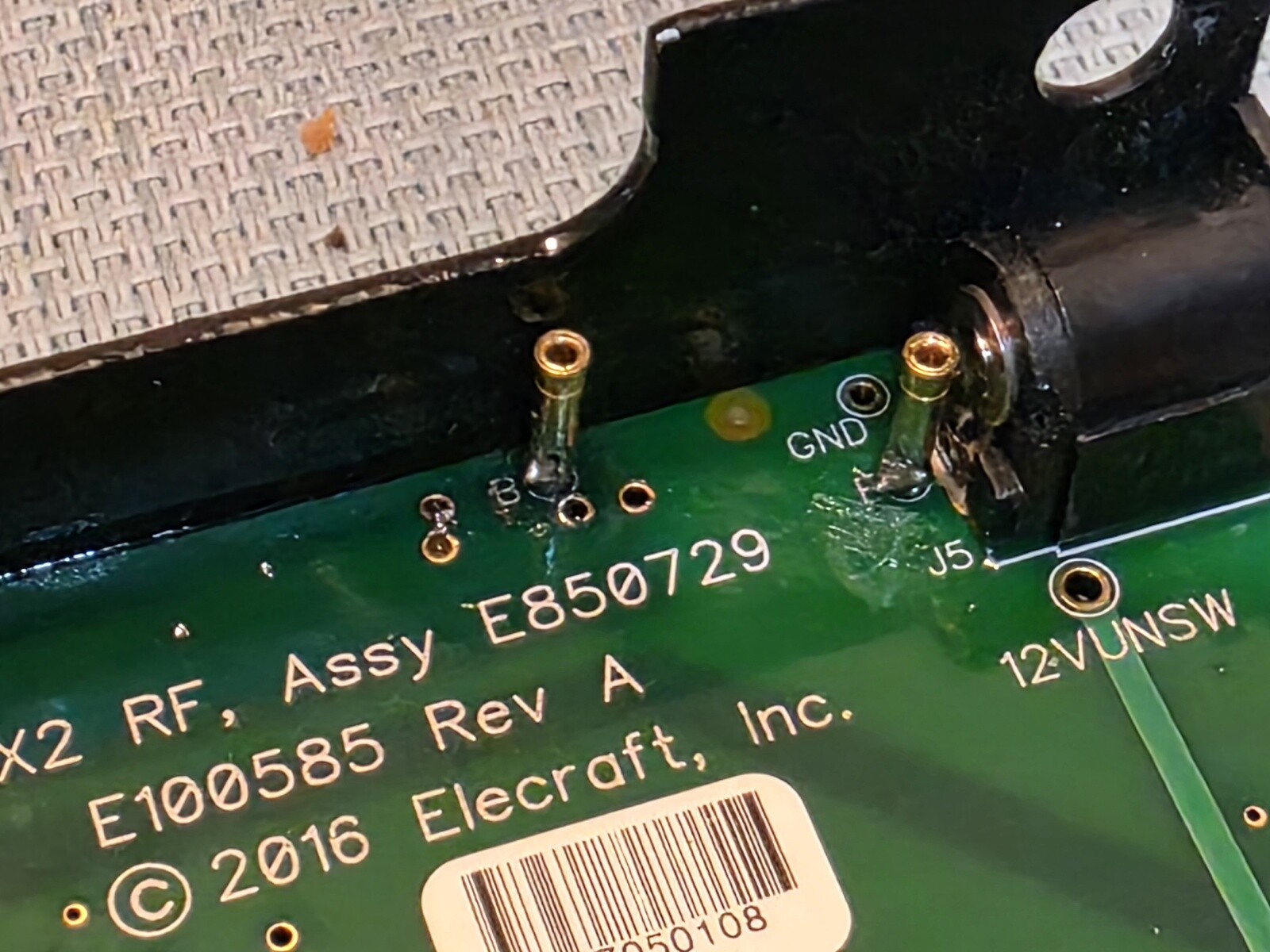
Dear God. What a tense install. It is 99.9% a doddle. Those pins though. Pin E went in just fine. Pin B got stuck as I accidentally covered the pad in solder and it wouldn’t come off with flux and solder wick to free the hole again. This was while the Pin itself was stuck in the hole but not fully seated. As I pushed lightly with tweezers to try and nudge it down a bit while heating the pad, the pin bent!
POO. CAME. OUT. ![]()
![]()
Luckily it wasn’t broken off. After that it somehow magically seated in place. A miracle.
All done and buttoned up. Seems to be working like a charm. Not as much of a charm as a Yaesu FT-290R or FT-202R mind you, but close enough! ![]()
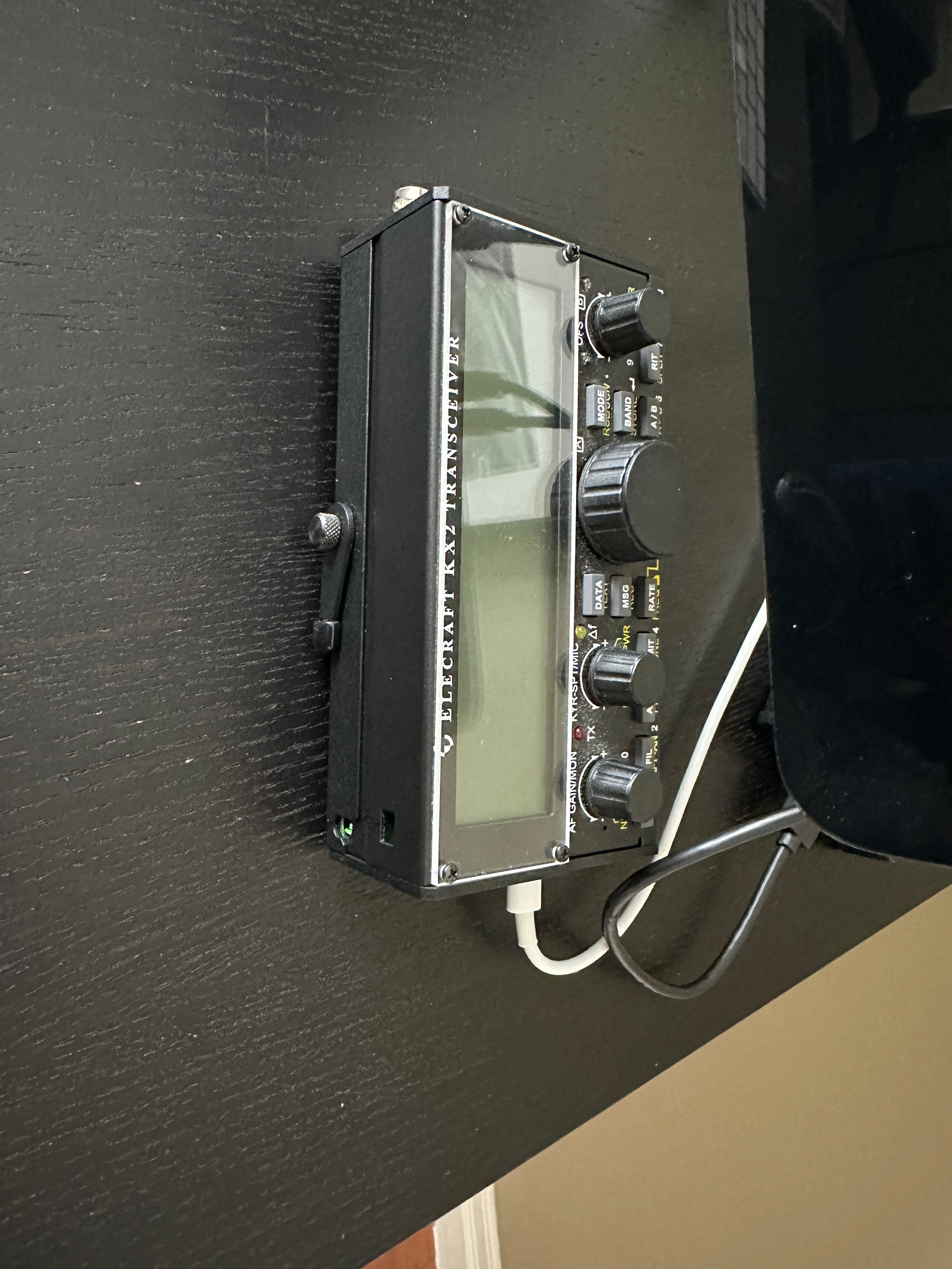
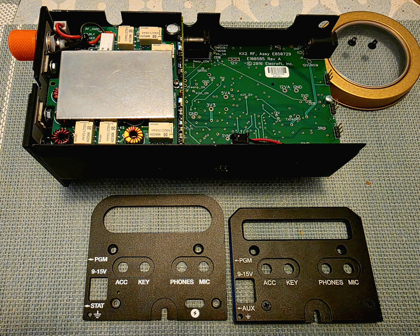
Only thing is, the new side panel is a different size to my other one. So my KX2 is a bit on the wonk. I need to find a side panel for my BNC side of the KX2 now. Any ideas which brand does a matching side panel? Mine was the Windcamp one. See below comparison:
2 Likes
Your side plates are not the original SideKX plates but possibly the Windcamp ones. They came out sometime after the SideKX plates and cover had been on sale.
3 Likes
Even on my KX2, the filled hole successfully resisted desoldering … so I simply cut off the soldering pin and butt-soldered the socket using a wire to position it.
2 Likes
Yup. Mine are Windcamp. Ah well, a wonky KX2 it is so! ![]()
I’m more pleased I got the pins fitted than anything. Now need to RTFM to make the settings stay after power off as I have to keep setting the board settings every time.
Charging works perfect though. Massive game changer! Thank you everyone for all the hard work behind this project, it is amazing work!
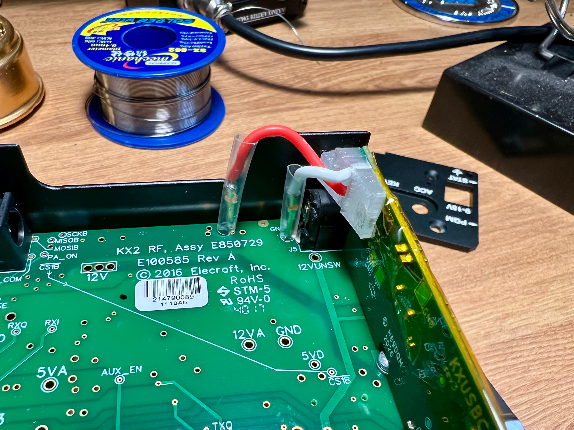
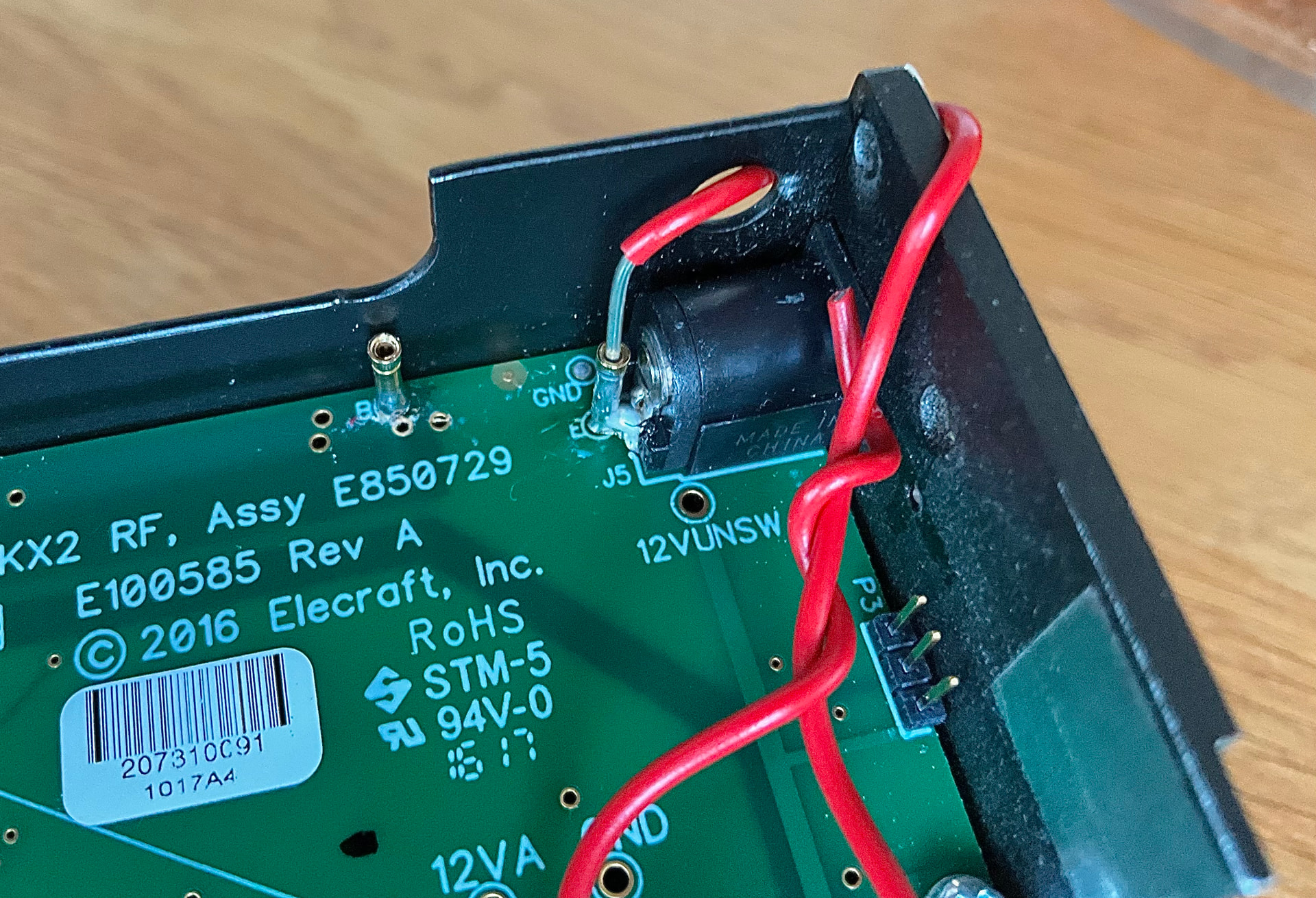
Here’s my appalling solder work for everyone to tear to shreds (the white stuff is the dry flux, I applied it with a cotton bud so as to not drown the board innards).
I believe @G7UFO Neil has plans to address this.
1 Like