Continuing the discussion from KXUSBC2 – Internal USB-C charger for the KX2 (Part 1) - #100 by MM0EFI.
Previous discussions:
Continuing the discussion from KXUSBC2 – Internal USB-C charger for the KX2 (Part 1) - #100 by MM0EFI.
Previous discussions:
RE: @MM0EFI - Mega! @G7UFO please stick my name on your list for my wonky KX2 sir! Please and thank you. ![]()
In other news, a shame BHS closed down. After today’s antics with that pin I need some new pants. ![]()
Previously, on "THREAD PART 1”:
I believe @G7UFO Neil has plans to address this.
I do have a plan. Fraser @MM0EFI kindly sent me his Windcamp plate so I can measure and mock up a compatible plate for @HB9DQM to check over. I’ll get a few made up and offer it as an option.
Anyone who has a SideKX one who’d like to swap it out - we can arrange that (when I have them in hand).
![]()
Yes please! Though it’s probably a pain logistically (An Post would stick their oar in) so happy to pay my way. Whatever works best and saves you a headache. ![]()
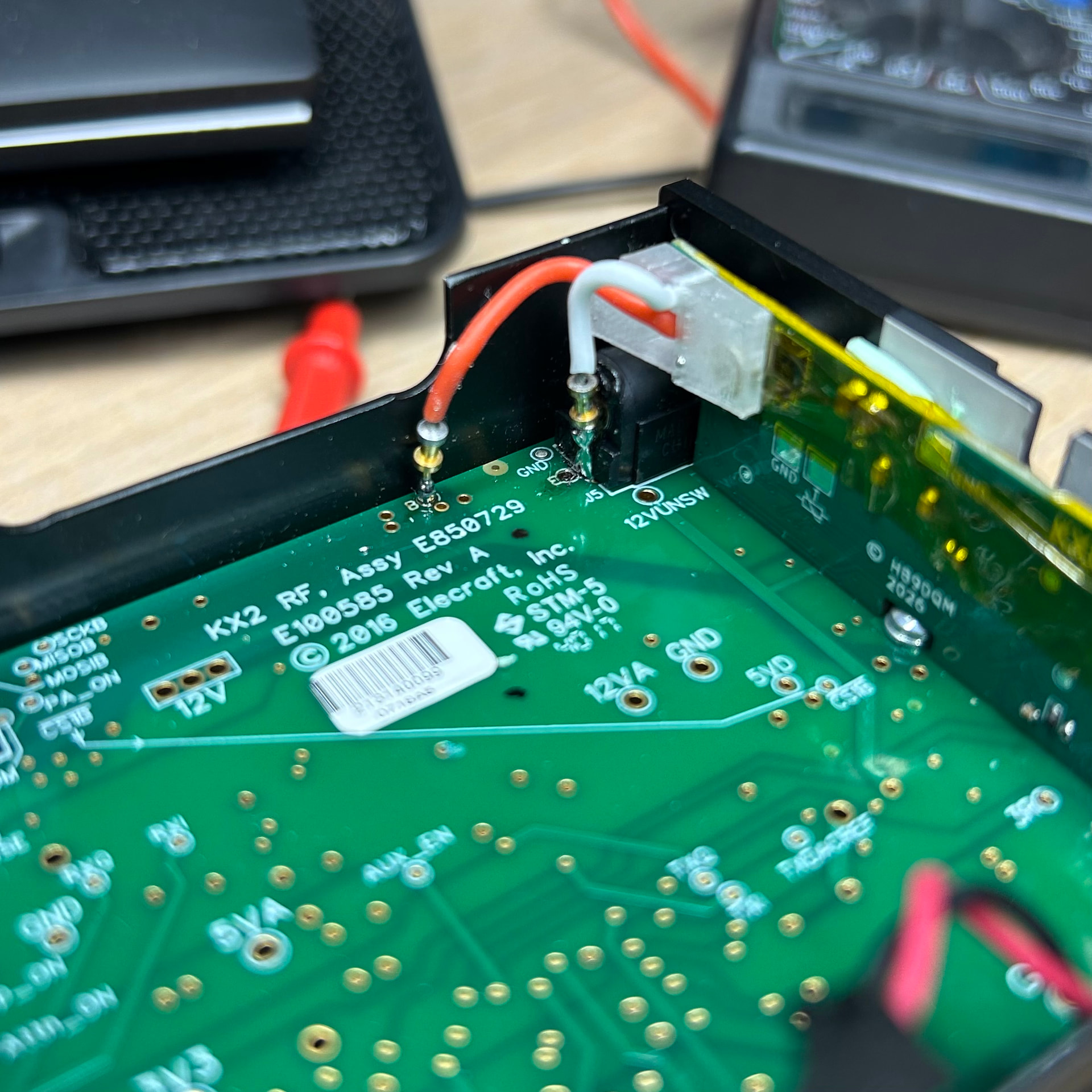
I got my board. Thanks @G7UFO
Instalation went well; I made a decent soldering job. I put everything back together and sucess, the led shows that the battery is charging.
Then I realized I forgot to place the thermal pad over U1; I dismantled everyting, stick the pad carefully and put everything back together.
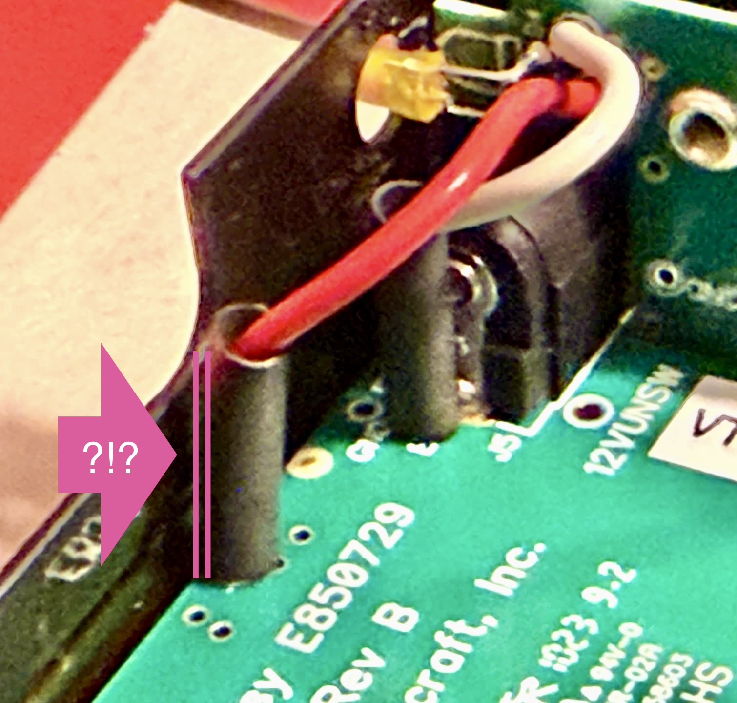
Now there is some intermitment issue. If I press (even very gently) the front side of the KX2 (where you attach the Elecraft key), close to the board, the led goes off (with or without battery installed). There’s a short circuit/bad contact somewhere. Any clue?
Seems good there; I tried to put a small bit of plastic sheet in between pin and case with the exact same result and behaviour.
I also noticed that when I remove the side panel to inspect the board, the LED does not turn on, even if I gently press on different parts of the board or radio. It’s only after I screw the panel back in place that the LED only comes on… intermittently. This makes debugging a bit more difficult…
I haven’t heard of this issue before. Some ideas to try:
If the board doesn’t restart, then the solder points of the LED may be damaged due to mechanical stress. If the board restarts, then there’s a short circuit somewhere.
Thanks for the hints Manuel.
I inserted a piece of plastic as you said and nothing changed.
All my tests were with the back covered removed.
The board indeed didn’t restart when the issue took place; the LED simply came back as before. So it is (was, coming back to this below) probably an issue with the LED solder points.
Now with all the manipulation of the board, the LED eventually came off ![]() This thing is not tiny, it’s a speck of dust.
This thing is not tiny, it’s a speck of dust.
Is the board supposed to work without the LED? I connected my battery (12.0V currently) and USB power for a couple of hours and the voltage did not bulge.
Anyway my options are:
Yes, the board (or more specifically, the LP5815 RGB LED driver IC) does not care whether an LED is connected or not. The only thing that matters is that the pads where the LED was installed are not short-circuited.
Try connecting your phone to the USB-C port and see if it gets charged by the KXUSBC2. If it does, then the other direction should also work.
You can also check whether the clock on the KX2 is running, as that is another sign that the MCU on the KXUSBC2 is working.
USB-C delivering power and Clock is running/time remembered after power-off. So it seems the board is working.
Let me try to charge the battery again.
Thanks again for the support!
Just charging up my KH1 ahead of activating tomorrow and it occurs to me that Manuel @HB9DQM owns one of these too… ![]()
![]()
If you’re unable to find someone local, you can send the board back to and I can re-solder the LED. I’ve just added a few of them to an order I was placing at Digikey so I’ll have a new one ready to go.
Thanks also to all who helped with the debug!
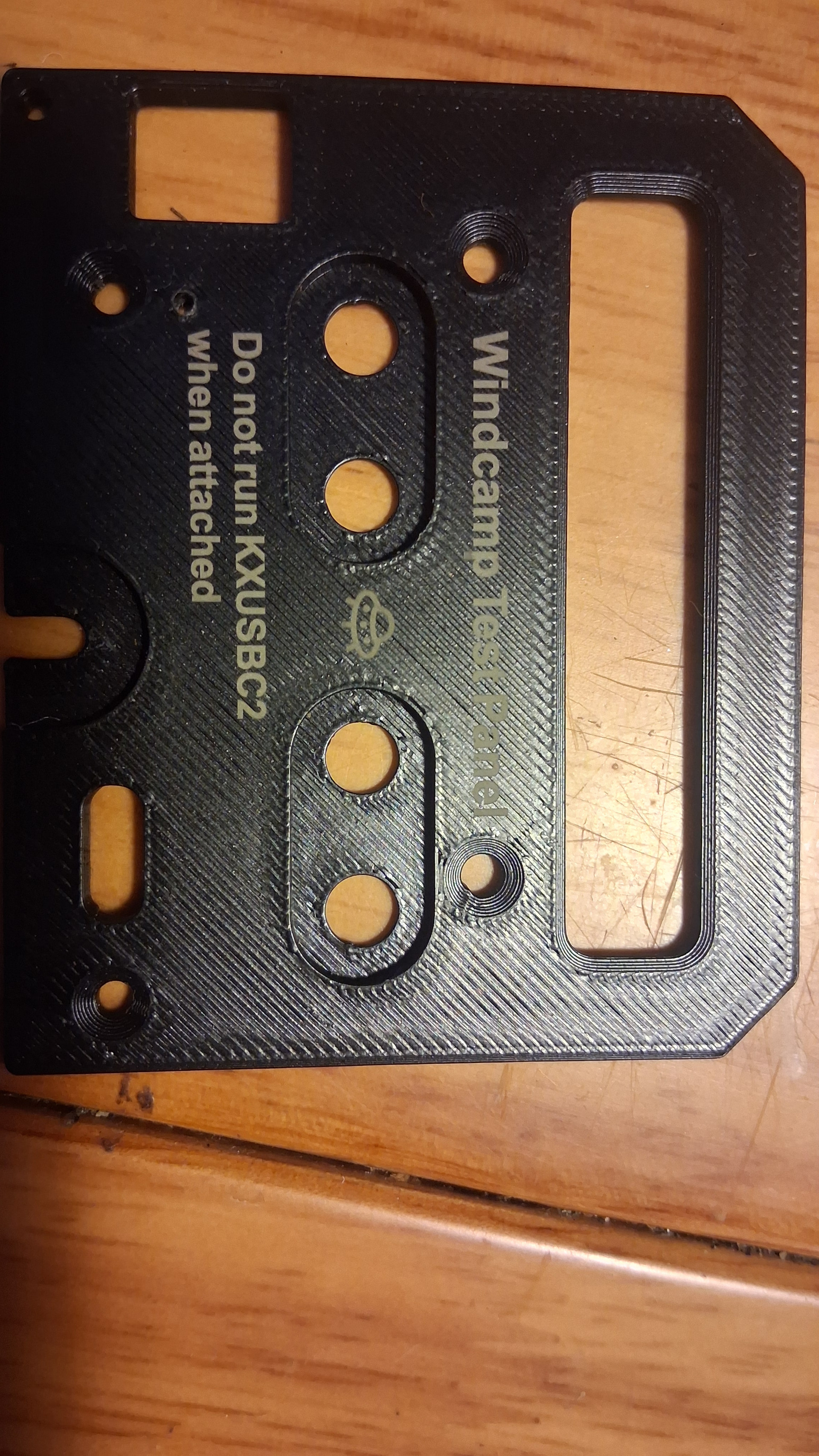
New Windcamp compatible end panel looking fine, and a great fit.
This is a 3-D print plastic prototype, just in case anyone is confused.
Thanks Neil @G7UFO
Ha, yes - I don’t think that’d work well in use ![]()
I’ve held @MM0EFI ‘s original panel hostage here in Durham for measuring and comparison. A small issue with the screw tolerance was fixed today I’ll be placing an order for these over the weekend.
That’s great work. Nice one gents, looking forward to fitting my KX2 out with one so it is non-wonky soon! ![]()
![]()
I also wanted to share some feedback on the KXUSBC2. I installed it over the weekend, along with the SideKX rail on the opposite side of my KX2, so it was quite the modification session.
The KXUSBC2 installation itself was straightforward overall. The one real challenge was soldering the pogo pins: the E-pin hole was significantly undersized, so I chucked the pin into my Dremel and sanded it down until it fit snugly but smoothly. Problem solved.
For anyone who has already tackled the SideKX rail installation: the KXUSBC2 is a walk in the park by comparison. Wrangling the nuts and washers back onto the PA transistors on the right side was far more nerve-wracking than anything the KXUSBC2 threw at me.
One gotcha worth mentioning for future installers: I briefly panicked when I couldn’t get the KX2 to power on via USB-C. It turns out the battery must be installed. Powering the radio solely from USB-C without a battery doesn’t work. That little discovery cost me a few unnecessary re-checks of my solder joints before I figured it out. ![]()
Many thanks to Ian for the careful and well-organized component packaging, and to Manuel for coming up with the concept in the first place!
![]() Thanks for the feedback – I’m glad to hear that!
Thanks for the feedback – I’m glad to hear that!
Yes, the KXUSBC2 is designed as a battery charger only, not as a PD trigger for powering the KX2 directly from USB-C. I have added a note about this to the installation guide now.
I have thought about this type of use (no battery, USB-C input only) – the charger IC supports it, but it would require rewiring the connection between the battery and the KX2, so that the battery no longer connects directly to the KX2, but with the KXUSBC2 in between. This would have made the installation too complicated, either requiring modifications to the KX2’s PCB, or soldering the battery wires directly to the KXUSBC2 instead of using the barrel connector. Either way, I decided that it’s not worth the effort.
I fully understand and support your design decision! It’s much better the way it’s now. I also think it would have been much more of a hassle to rewire the connection between the battery and the KX-2.
Hopefully everyone who is waiting for their order has received my email but for those who see this first:
The excitement of finally receiving the batch 2 boards was immediately tempered by finding one component had been placed incorrectly and so I currently have 50 unusable boards sitting on my workbench.
My plan of action:
I’m working with the supplier to remedy this.
I’ll be placing a replacement (larger) order and requesting it be expedited.
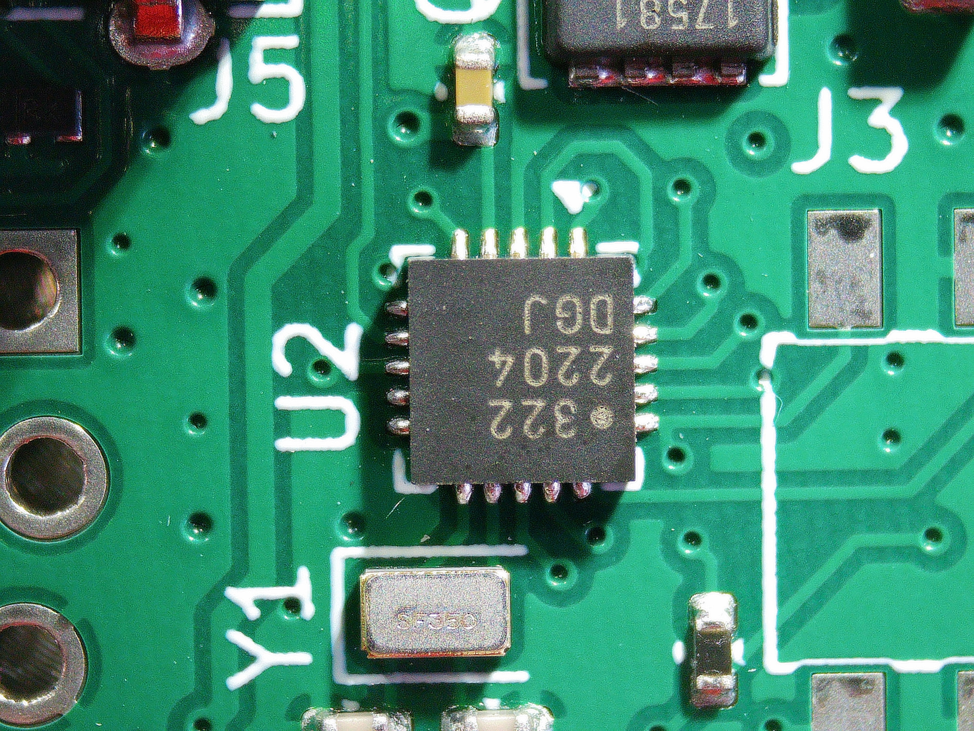
I’ve contacted some local companies with a view to having these repaired. The component in question is 3x3mm and I’d be concerned about damaging it and the board if I attempted this myself.
Also looking at having these produced locally in some capacity to protect against future issues like this.
I appreciate everyones patience with this. Please drop me an email if you have any concerns or would like to cancel your order.
As a further update to the above, I’ve just sent three boards off to a SMT repair company here in n/e England for them to repair and return to me for testing. If all is good I’ll send the rest of 'batch 2’ to them for repair which should get us back on track.
Thanks to @HB9DQM for the quick assistance with debugging the issue. Step 1: is U2 soldered correctly? No. No it is not:
Oh, I’m adding updates as I have them to this page.