FT-857 LiPo Batteries (again) - A new possible solution

I’ll be adding a fuse in-line with the positive. I use two fuses on power leads from my PSUs (as they come like that on radio’s more-often than not), but on something like this battery, I’ll just use the one on the positive too.

I’m not worried about invalidating the warranty, I’ll take the risk on £50.

2 Likes

Those of us who have seen what can wrong always use one in each lead. :fire:

Just sayin’…

1 Like

I’d be interested in hearing the argument for using two fuses from a battery source or properly isolated PSU. Surely the circuit is broken with a single fuse?

I am aware that in mobile installation where a negative ground issue can result in high-current through other vehicle equipment.

1 Like

Here you go…

“Those who cannot remember the past are condemned to repeat it.” – George Santayana, The Life of Reason, 1905.

1 Like

Nope.

This happened very recently (may this year) to someone in the 23cm group.

The setup was a battery into a Y-adapter for providing power to 2 items (FT-817 + Linear). This is what was posted.

The power pole y adapter I use to power the FT817 and linear went open circuit and at the same time I noticed the 817 went onto internal battery. It appears that when the negative to the linear broke, it drew current through the coax patch lead from the FT817. As the DC feed goes via a choke to the chassis ground, it pulled too much current through the board track and burnt it out. I will have to bypass the burnt out track between the DC socket and choke, and at the same time I may fit a fuse in the negative on the 817 DC cable ..

Hmm, I’m still not convinced. If the fault current wasn’t enough to blow the positive fuse on the battery, then why would it blow a negative fuse, if installed? The sum of the current coming out of the battery positive terminal must be the same as the current going to the negative terminal, no?

Typically, I fuse my batteries for the current it is rated for, but also fuse each circuit connected to it accordingly.

For SOTA I fused the 18Ah golf trolley battery at 25A into a power-pole connector. as that’s the max current I want to draw from it, which is sized for connecting directly to the FT-857. However, if I were to connect the IC-705 to the golf trolley battery then the cable I plug into from the powerpole connector out of battery to the IC-705 barrel port has a second fuse in line, rated at 4 amps to ensure the radio is suitably protected. I sometimes use a power-pole Y connector to also connect an 80W 2m linear to the battery too, which had a 15 amp fuse to the linear (although more often I would use the internal battery for the IC-705 and just the battery on the linear).

Perhaps I am missing something subtle from the explanation in the linked post? A circuit diagram of how it was hooked up would clarify what happened; after all a picture is worth a thousand words!

Dave.

1 Like

Because the fault current blew up PCB tracks before the positive fuse blew. i.e. the awfully expensive PCB tracks protected the cheap fuse.

1 Like

It’s also not clear to me the exact scenario that requires a fuse in the negative lead.

You have two devices (rig and amp or transverter) connected to the same battery. If you have a fuse in the positive lead before it splits for each device then that should be enough protection. If it isn’t then please explain.

Why would a fuse in the negative line blow any quicker?

It would.

I’m not saying that Andy is wrong, just that I want to understand.

1 Like

The LiFePo battery protects itself against overcurrent via the BMS and does not require a fuse.

Each connected device requires its own fuse, which is rated for the device’s power consumption. An FT-817 cannot be protected by a 25 A fuse connected directly to the battery.

73, Peter - HB9PJT

2 Likes

No doubt Andy will clarify, but my understanding was that the system in use had both negative and positive earth (chassis) equipment… then again my memory might fail me.

I always use separate batteries for the transceiver and linear or transverter. I generally set the transceivers (KX3 / FT-817 / IC-703) at around 2.5 watts to drive both HF and 2m linears. Considerably less is required to drive the 23cm transverter. At these power levels the transceiver can be run off a small 3S LiPO or 4S LiFePO4 with negligible weight addition.

Not sure if something has been lost in translation? I agree that LiFePo tend to have BMS which can limit current and disconnect the battery when the cell voltages get too low. However it is still important to fuse the battery. If the cable connecting the battery shorts there is a serious risk of fire which the BMS will do nothing to prevent. The noted LiPo batteries tend NOT to ship with BMS installed, due to the intended use. Intelligent chargers which monitor each cell are paramount for safe management and charging of these LiPo’s.

I agree, for the FT-817. I presume it would be more like 2 or 5 amp fuse. It is just as well I am using an FT-857, which should be protected by a 25A fuse! :rofl: In my case, the single fuse protects both the battery from short circuit and the equipment from excessive current.

73’s

Dave.

Dave, this BMS provides protection against:

  • Overcharging
  • Deep discharge
  • Short circuit
  • Overload
  • Temperature (input for temperature sensor (10kNTC))

A fuse is not required.

73, Peter - HB9PJT

I have experienced the problem, luckily I got away with it.

Ft817, SG Labs transverter. I had attached the 817 power lead to the battery, and the coax between rig and transverter.

As I offered up the live battery lead to the transverter, the centre (positive) of the barrel connector touched the metal case. At this point, the only return path to battery negative was through the coax braid to the 817, and along its negative lead.

The battery fuse blew, and I got away with it because it was only a 5 Amp fuse. Had I been using a linear I would have fitted a higher current fuse, and the outcome would have been different.

A single radio and a single battery can probably get away with a single fused +ve feed. The problems arise when more than one item is powered from the same battery,

The classic case for dual fusing a radio supply lead.
The car has a short very high current strap connection from -ve battery to chassis. The positive runs though a contactor unfused to starter and other high current +ve feeds run to fuse box(es). All items are fed from fused supply.

This is fine and dandy and everything works. Then with age, the -ve chassis strap starts to degrade, corrode, go higher resistance or fails open. At this point the starter may seem slow, intermittent faults with equipment or when the strap goes open, the car is dead. No problem, just fix the strap.

You install a 100W HF radio in a car. You have a dual power lead (typically red/black figure-8 cable) and this runs from the radio through the cabin firewall into the engine compartment and to the battery. You then have a single fuse in the +ve. This fuse should be near the battery connection not the radio so when it blows you do no have a long length of “live” wire running from the battery to the cabin. The antenna will normally have a direct bond to the chassis/body where it mounts and then a length of RG58 or such back to the radio. So we have direct -ve connection to battery from radio. Fused connection to +ve connection to battery. Antenna bonded to body and connected to radio via coax shield.

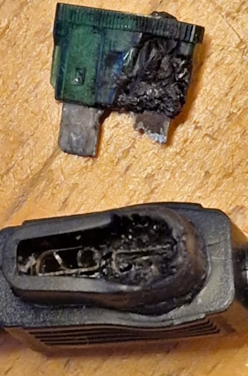
Now in this case when the -ve strap starts to fail, a lower resistance path exists from the radio negative lead to the radio, through the PCB -ve tracks to the antenna connector outer, through the coax shield to the antenna and thence to the car body. As it’s lower resistance, any current needed by the car will flow through the PCB tracks in the radio. i.e. that typical 3mm X 15mm earth bonding strap than can carry all the starter motor current (100-300A) is not carry much current. The fuse in the radio +ve wont blow because there is no current in it. All the fault current is carried across the radio PCB tracks. They don’t like that and burn up.

A fuse in the -ve lead would fail quite quickly in this case, hopefully soon enough to prevent or at least minimise any damage to the PCB etc. Hence manufacturers provide dual fused power cables because you can be quite sure avaricious hams would skimp on the few £’s extra inline fusing would cost.

This is a case of the battery powering the radio and other items. All the factory fitted items in the car pass their return current straight to the chassis. But we have 2 -ve returns with the added radio. As I said at the start, a single radio single battery can get away with a single fuse. As soon as you add another item on the battery at the same time then multiple -ve returns may yield an unfused path. May is the operative word. So fuse both +ve and -ve in all cables. Simples.

In my case it was when I forgot a battery and I had an FT817 and 13cm transverter powered in common. Also I’d had to cut off a connector (2 items 1 battery) and wedged the cables into the power connector. Also as I always used 2 batteries I only needed a single fuse per cable. Until this time. The linked article describes the fun locating and fixing the fault.

What’s the saying “he knows the cost of everything and value of nothing” and I have a degree in electronics. So I knew I should have had 2 fuses but I’d been cheap with the cost of components and use of my time. Now everything is dual fused. Gosh looking now 5x inline car blade fuse holders with weatherproof covers and 5x 25A bladed fuses is £10 inc p&p. So £2 an item to possibly stave off an expensive issue.

It may. It may not. But a fuse may save much PCB damage whereas no fuse increases the chances. For the cost of a few £’s it’s just simple and straightforward potential damage limitation.

And I’ve done and Ian G7ADF’s chum did it. It’s easier when you’re out portable and suddenly there’s DX and you faff about with cables etc.

Except we’re talking about an unfused LiPoHV with no BMS here. I only have one LiFePO with a BMS. All my other LiFePO and LiPos are used raw with no BMS so dual fusing makes sense.

The fact remains that the cost of fusing both is so monumentally cheap compared to the cost of a replacement radio that it really seems to be false economy to omit them. I’m sure everyone on here can come up with a million billion reasons why these fault cases wont apply to them because they do it XYZ way or they’re clever or special in some way or yada yada yada. My advice is to just fit a damn fuse in each cable.

Any fuse can cause problems. Not when it’s new, but later on. I’ve read so many reports of problems with 100-watt TRX units where the maximum output power isn’t being reached. After cleaning the fuses and fuse holders, everything was back to normal. The system becomes more reliable once all unnecessary fuses are eliminated.

73, Peter - HB9PJT

73, Peter - HB9PJT

I think the advice to put fuses in the -ve and +ve leads is good but too simplistic. The fuses need to be correctly rated for the equipment they are protecting.

This won’t stop the PCB track burning out in the FT817.

If the transverter’s +ve supply touches the case and the current flows through the coax the fuse in the negative is not going to help. The fault current may not be massive due to the resistance in the coax etc, the PCB track will burn out and the fuse won’t even blow. There’s also no point having a fuse rated higher than the current the battery can supply as it will never blow during a short circuit.

So the way to protect your equipment is to have correctly sized fuses in the -ve and +ve leads for each individual piece of equipment. With a 2A fuse in the -ve lead of the FT817 that might protect you from this fault but the PCB track might still fail first.

Another scenario is where you have a rig and a power amplifier. The amplifier will need protecting with a, say, 10A fuse so it’s even more important for the rig’s -ve lead to have a low current fuse as the 10A won’t protect the PCB track.

Fuses

1 Like

That’s not the fuse value for an 817 but an 857. But I must admit I was mixing Dave’s 857 with Paul’s 818.

My KX2 lead and the 705 have 3A fuses. Getting the value right is hard as I have an output to connect the handheld if it needs charging or running at 5W. But I don’t TX on both at the same time so I’ve not blown them yet. IIRC a fuse should be able to survive a continuous 130% overload

Will the PCB track on an 857 be any thicker than on an 817? I suspect that it’s possible there may be scenarios where no fuse will protect everything.