A 1/4 wave centre-loaded vertical with multiple taps on the coil to tune different bands seems such an ideal SOTA anntenna, that I keep coming back to the idea. However, on each attempt I end up giving up in frustration.
The design is based off a 1/4 wave vertical wire on a SOTA-pole, cut for 20m, with 4x approx 5m ground-laid counterpoises. Inserted 2/3 of the way up the 20m 1/4 wave is a loading coil on a plastic pipe that slides over the SOTA-pole and sits at the required height. The coil can either be bypassed for 20m, or the antenna connected to the correct tap to tune the antenna for 40m or 60m
Building this at home was simple enough, with a bit of adjustment from the theoretical no. of turns on the coil for each tap, the antenna could be built to tune at the required frequency on each band and operate as hoped.
==
The issue is repeatability. Each location I erect the antenna, the tuning appears to have changed and I seem to be forever adjusting the antenna length to get it back resonant at the required frequency. Even within the duration of today’s activation the 40m centre-frequency wandered off on me with it starting ideally located with SWR reading 1:1 at 7.090 when I started, and by the end of the activation the minimum SWR frequency having disappeared somewhere off the bottom of the 40m band.
Now, I assume that this is all due to my ground-plane / counterpoise setup, as nothing else changes from deployment to deployment or time to time. Specifically:
changes in ground conductivity and capacitance between my counterpoises and ground; and/or
the ‘random counterpoise’ approach I use - ‘random wires’ snaked out from the antenna base rather than cut to a specific length and held taut.
So:
Is my ‘X’ of 4x5m counterpoises realistically enough for this antenna?
Should I be pegging out the counterpoises taut and straight?
Should I be aiming for any specific length of counterpoise (hitting or avoiding specific fractions of lambda)?
Any other suggestions before I put it back in the cupboard again and go back to the trusted old EFHW?
I have used verticals with radials for many years and have concluded that, unless the ground plane is very large (like a steel shed roof, or a swamp) and non resonant, a radial based ground plane must be resonant for best results, and for that to work above varying ground conductivity, it has to be elevated above said ground and must be resonant on the intended operating frequency.
The random wire approach never works for me. The radials lying on the ground doesn’t either. But put up 2 or more elevated resonant radials for each band of use, it works fine. And that also applies to commercial trapped verticals, I have used a Hygain 14avq (gained a dxcc in Brunei - easy when you are the dx, but before the tuned radials it was hard work) and also a Hustler 4BTV. Both were used with tuned radials above ground.
My 20m SOTA vertical has 3 tuned radials which slope towards ground but as the ends are high voltage points, they are obsessively insulated from the ground and are as far above ground as I can make them in each installation. Having a cord attached to t he end of the radial to space the end out from the ground stake works to keep the end of the radial above ground. Having it too close to the ground detunes it, as per any antenna, so tuning it at the exact configuration to be used in the field is important. Elevated radials make the antenna less dependent on ground conductivity and also improves the efficiency. Taking lossy ground out of the antenna impedance removes a loss component in the impedance.
Andrew VK1AD has been using a centre loaded vertical very successfully, using elevated radials.
I equate the tuned radials of a vertical with “the other half” of a dipole. The vertical is half the antenna. The radials deserve equal attention to the vertical. For this reason I do not regard the casual use of a small bit of wire hanging off an end fed antenna transformer as a real counterpoise. Refer to Cebik’s discussion of what a counterpoise is. It is not a single wire, it is a mesh of many wires close to the ground, creating a capacitive connection to conductive earth. On a rocky summit, even a counterpoise of that type is essentially useless as the variations in ground conductivity will drive you nuts.
I made up an antenna using a Hustler 40mm loading coil from my mobile. I supported the base of the antenna on half a metre of 40mm white pvc pipe. I had 3 1/4 wave radials on it for the band in use at the time. The vertical shaft below the loading coil is 1.8m long and the coil screws on top like normal. Only experimented in my yard with it chased several SOTA ops out on summits with it over a few weekends they always seemed to hear me with 10w to my ic 703 I had back then. Every time I think of that rig I kick myself for selling it. Came to the conclusion it was easier to carry a squid pole and wire dipoles to summits so never used it to activate with.
Also you may thinks about a 1/4 wave radiation angle is quite high compared to other antennas, if angle is higher it wont radiate at well as an antenna with lower take off angle.
Good luck and a great experiment.
Regards Ian vk5cz …
regarding counterpoise … for grounded radials you only need 0.1 of the longest wavelength used. So for 40m and anythink below… 4x 4m would do. Feedpoint is only 3cm from ground.
I am using an HFP1 similar MP1, but exchanged the radiator with a 5m mfj stick. Everything from 5Mhz to 18Mhz workes, BUT
in dense forrests tuning might be a problem especially on 40m
in winter storms ice makes the coil and the antenna untunable within minutes
it is a Dx Antenna - worked ZL from EU with 5 W, but the signal for distances up to 700 km will be usually low (depends on conditions and band)
soil has an impact as well
However, in summer worked many DX in QRP. A good ATU like the one in the KX2 solved some of the problems and extends the range to 5-28Mhz.
For elevated radials you need quarter wavelength radials. However, sometimes when you have only one radial and the endpoint is elevated, the antenna might behave a bit similar with a dipole. In this case the feedpoint should not be too low either. Some activator suggest the use of this solution as it covers better the area up tp 700km and above…
Wire antennas dont have the problems mentioned above… but are longer and might be a challenge to errect in very small places. Depending on the antenna, they might have a better gain as well.
I suggest that the 0.1 wavelength guideline is from commercial MF broadcasting practice, where they use 120 radials, buried a metre down in damp soil, which does make a good groundplane. Otherwise with a small number of radials, having them on or in the ground is just a source of losses.
Whenever people report varying results with verticals or end fed antennas, it invariably means their ground plane, counterpoise or earth currents are going in places they did not plan for. Taking the same antenna to different sites and getting different results means the ground conductivity is varying between sites. Making the antenna system independent of ground conductivity is the only answer for a lightweight portable station, this is where elevated radials are superior to radials lying on the ground.
I agree with your argumentation. Elevated radials are better than grounded radials. However, it can be a buyout for small locations: ease of use vs. performance. e.g. radials of 4m vs. 10m for the 40m. In some of the locations here, there is not much space…
A portable antenna is always a compromise
The main reason why I will be looking for a wire antenna is the coverage in the area up to 700km and the problematic behaviour of the coil in winter.
I’ve found the performance of a 1/4wave GP with 3 1/4wave radials sloping down at 45degs to be repeatable on 12 and 10m. The sloping radial does make a 20m 1/4 wave too big for my poles.
I also have 1/4 wave GPs with sloping radials for 20, 15, 12 and 10m. They all work well with the US and Canada consistently worked on all bands. Best results were VK and ZL on 20m and Argentina on 10m. The 20m GP needs my 10m pole; the others fit on the 6m pole.
They are single band but are pretty quick to put up and take down.
EDIT: This is with 5W CW except on 10m where it is 3W.
I settled on elevated radials for this reason, by using elevated radials over ground laid radials you remove the issue of ground loss and detuning. Each 1/4 wave radial on the ground is no longer a 1/4 wave, in fact it’s a different length on different ground … Electrically.
To multiband such an antenna could easily be done with link’s and M7BIA did this with a two band version. For the same match over differing grounds I would go with elevated radials.
Hi Matt.
I only use 1/4 wave when I know there isn’t enough room at the summit.
I use an unbranded Chinese telescopic antenna of 5.2m long and 10 radials also of 5.2m
I made marks on both the antenna and the radials with an indelible marker for 18 and 21Mhz since when fully extended it is perfectly adjusted for 14Mhz. For 7/10Mhz I use a coil.
The radials in 14, 18 and 21 are extended as far as possible evenly separated from each other. But for 7/10 I join 5 radials in one branch and 5 in another branch and I extend them in opposite directions since it’s the only way that I can tune the antenna. I have no idea why but with this antenna I have worked the most of my QSOs with Europe as well as S2S with USA and Oceania.
I had mixed results with swr / tuning on verticals, similar to yourself. I did find that sloping radials were better. I used a 7m pole with a 5m vertical, which gave me over 1m above ground for sloping radials. I didn’t get into coils / switching, but I spent ages tweaking the radials almost every time that I eventually got fed up and now almost exclusively use a 20m end fed wire in inv V, or L if space is tighter.
The key lesson learned is that it is not possible to design a tuned version that would work without a tuner in varying deployment conditions, e.g. ground characteristics, radials deployment, etc. If you have a lot of time on the summit, you may be able to tune the antenna by playing with the radials deployment, but that is annoying and not guaranteed to work.
So my next design made the Elecraft T1 tuner the center of the design:
The core idea is to do the biggest part of the compensation (for 40m, mostly), by means of a high-Q inductor at the feedpoint, and the fine-tuning by the T1 auto-tuner. This allows for fast deployment in varying environments.
The next planned iteration will replace the T1 by a simple LC match and either a Tayloe SWR indicator or the BlinkySWR. The L of the LC match will be just a bit of extra inductance on the loading coil, so I hope to need only a variable capacitor and maybe 1 - 2 switchable additional Cs in parallel for ca. 20 - 1000 pF.
But the main lesson learned is that neither a vertical nor an up-and-outer matches reliably in changing deployments. Most success stories are based on just too small a sample size ;-).
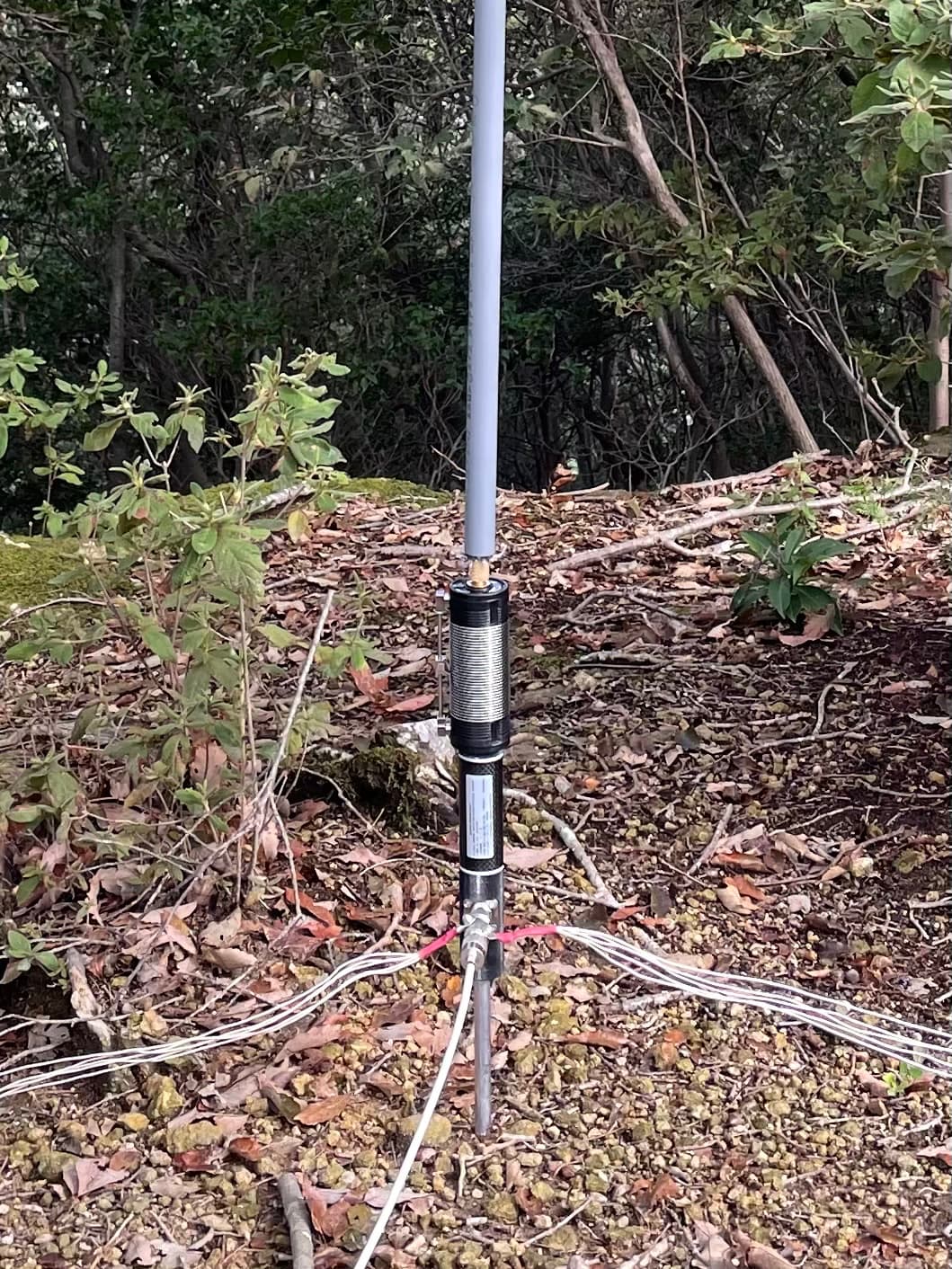
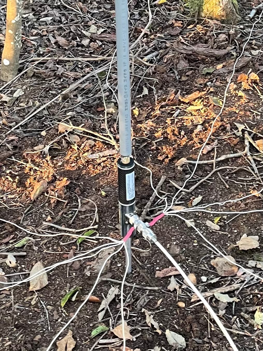
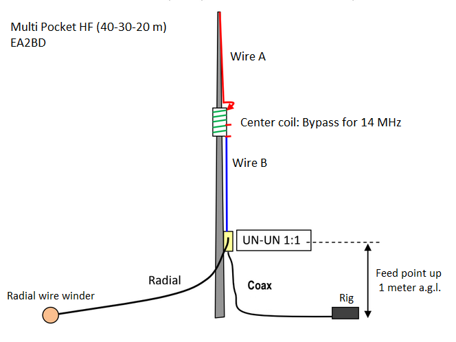
Some years ago, when starting doing activation for SOTA I built a compact multiband vertical antenna. I wanted it for 40-30-20 meters, and decided to have it center loaded, instead of base loaded.
I prepared a quarter wave for 14 MHz firts, with a single sloping radial.
Sure an elevated radial would be better, but I decided to have that sloped radial for ease of final tuning, as there are variation between summits. Having the chance of reducing or enlarging its lenth over ground was the easier way to have some flexibility. In the end it was very easy to fine tune for minimum SWR this way.
Then I added a custom made center coit with two taps. The coil was bypassed for 14 MHz but the taps were used for 10 or 7 MHz (10 uH / 25 uH).
Regarding the radial, the length was increased according to the band in use.
With this aerial I did some succesful activation, knowing that it’s a compromise antenna, but it was fast to deploy and quite appropriate for reduced space summits.
I’m currently using a multiband EFHW and find it a better performer than the shortened vertical, but I would consider the compact vertical again for these reduced space summits.
Using a single radial is easy and convenient for a fast tune process: you forget about the fixed length vertical radiator and simply adjust the radial length for minimum SWR.
I feel there are 2 potential reasons for ‘going vertical’:
Small footprint, rapid deploy SOTA antenna with easy multi-band operation
Low-angle SOTA DX antenna
My motivations lie 95% with option 1 - the small footprint, easy deploy, rapid band changes. Something for tight summits (or crowded caravan parks) where stringing out an EF-40m-HW is not a good option.
Given that, I acknowledge all the really great advice on elevated 1/4 wave radials - and if I do decide to build a vertical for chasing DX, that will all be really helpful. But for my current purposes (limited space, fast deploy), if I can string up multiple elevated 1/4 lambda radials, then I can deploy the EFHW - so I’ll not be pursuing that direction for now.
@EA2BD - your solution looks very similar to my first (failed) attempt at this, except for your elevated feed-point and single tunable radial. I had no success whatsoever with the single snaked ground-laid counterpoise, but never tried tuning it or sloping it.
I will certainly play with that design, though it’s benefits for small summits depend on the length of that single radial.
I note the 1:1 UNUN - so you are feeding this as if it were a dipole at 50 ohms, not a vertical over groundplane at [EDIT] 36 ohms as I am?
What is the length of your single sloped counterpoise. I’m guessing 1/4 lambda given the dipole-like impedance?
==
@DH5ST. So 4 counterpoises @ >=0.1 lambda was where I started with the ground-laid counterpoises I have currently. Switching from a single long counterpoise to 4 x 5m ones made a huge improvement in consistency, just not quite enough to avoid having to tune the antenna each deployment. I could go for more radials as @JP3PPL does, or longer (10m?) radials as @VK1DA mentions for 40m - it would be a good experiment at least to see if either decreases the variability in tuning (and if so which solution I find least inconvenient to deploy)
==
@DK3IT - On first read, I was silent screaming ‘but I want a tuned antenna, not an antenna tuner’. But rereading your points and thinking more clearly you make a very valid point:
The antenna is very close to tuned by the large centre-loading coil - generally needing shifting only a couple of hundred kHz to get back onto the desired frequency. So a very small adjustable LC (or even just C) tuning circuit would indeed probably do the trick. Something small enough to build into the UNUN case to avoid assembling additional connections & components in the field.
Thanks also to all other contributers not directly mentioned here. All posts above had useful advice in them. Feel free to scream out if I’ve missed or mis-interpreted your points.
Hi Matt
Let me throw another less common option into the pot …
A lot of this discussion has been around radials or counterpoise wires, raised or not. I use a different option here for the home vertical HF antenna and that is a “Loop on the Ground” antenna earth. Similar in construction to the loop-on-the-ground antenna, this transformer-fed radial field replacement was covered in an article in the October 2020 RadCom magazine (pages 44-45). Both home and portable set-ups are described in the article.
The loop on the ground counterpoise solution, as well as being easier to deploy also assists reception as when used the signals received have a lower background noise level.
73 Ed.
Hi Matt, you could read that UNUN as a coax choke if you like: it does not function as an impedance transformer but to prevent the coax braid radiates so that only the antenna is part of the radiating system instead of the antenna plus coax.
Note the impedance is around 50 ohm for the bypassed coil (14 MHz) but you can expect the impedance goes down when the coil is active…
Consider as well that the sloping radial (being most part of it directly on ground) adds losses that helps increasing the impedance: as a result the SWR will be good and the transceiver “happy” but the performance is not 100% because part of the radiation is lost in the coupling with the soil.
That is correct: I had about 10m length in the wire winder and had to strecht about 1/4 wave length for the operating band. When on 7 MHz I used almost 10 m.
Bear in mind that a single radial creates a pattern less omnidirectional compared to 3 elevated radials, more like a pointed oval shape towards the single radial, but the difference is not that big (it is not a beam!).
I used the antenna without any intermediate antenna tuner, and had to enlarge / shorten the radial length a few times to put that in resonance (or lowest SWR) being more or less repeteable.
I expect the on the ground radials as suggested by others in the thread is likely the main source of your variance.
But I once made a loaded vertical with raised counterpoise (or is it a single radial?) a la @GM4LLD. Was getting very confused trying to tune it when I first built it, until the penny dropped that the carbon pole was having an impact. ie as the vertical element moved around in the wind relative to the pole it was changing resonance. So if your pole is very carbon-y, and hence conductive, in my experience it may have an impact.