Interesting new SOTA Vertical Antenna

I have noticed that the maker recommends using a single radial with the budistick, as it is easier to fine tune the antenna when it is in lazy L dipole format than when you have 3 or 4 radials to tune, or need to adjust the vertical element.

However I understand that in such configurations, half the antenna current is flowing in the single radial and unless it is elevated, that half of the tx power is split between being radiated and being absorbed by the nearby ground, rocks, foliage etc, While the antenna impedance may well be adjustable to be a close match to 50 ohms, or is at least non reactive, that doesn’t necessarily translate into best radiation efficiency. Part of the radiation resistance is the loss resistance in the nearby ground, so exposing the antenna to that loss is undesirable.

While it is tempting to simplify a vertical antenna’s ground system to a single radial, and it looks good on an analyser or on the swr meter, using two or more elevated radials is better for dx and produces more radiated signal.

Perhaps one of the wspr-aided antenna comparisons will confirm that in due course.

Andrew VK1DA/VK2UH

I have always found that the Buddistick does need the elevated radial and many times you tune the swr by altering the elevated radial length.

When i left it on the ground I was not happy with the antenna.

Also the radial offers some directivity and I am sure the radial may radiate more RF energy than the short vertical element.

I think all the short whips would be similar.

I bought the newer version of the Super Antenna and their radials are full length.

Now that I joined the Linked Dipole Club I am convinced that is the better way to go if you can erect it on the summit , if not the vertical is the way to go. A proper 1/4 wave is ideal of course.

john ve3ips

I think everyone is aware of the BuddiPole Field Guide

and now for extreme SOTA the lawn chair challenge is a good one!

image

Has anyone made up an antenna using the aluminum hiking poles?

First ham to SOTA the 2 lawn chairs on a Summit gets a beer paypalled to them! I am thinking the Austrians might win this one by submitting into Northern Italy.

It looks like the QRP Guys have had lots of orders recently for this antenna as I’ve only yesterday received notification that they are shipping this kit to me - 11 days after I ordered it. I wonder how long it will take to get here? it’s often far quicker to order goods from China, India or elsewhere than from the USA. It always seems to take longer with the USPS.

73 Ed.

Yes, used my walking poles as a support only (Not as the actual antenna) for my HF link dipole on Lamington Hill GM/SS-172 last November:

I wanted to prove I could work DX with such a low dipole, and I did log NE4TN. I guess the antenna was 8 or 9 feet AGL at the centre:

52

73 Phil

PS I was running 8 watts output from a KX2

Hi all:

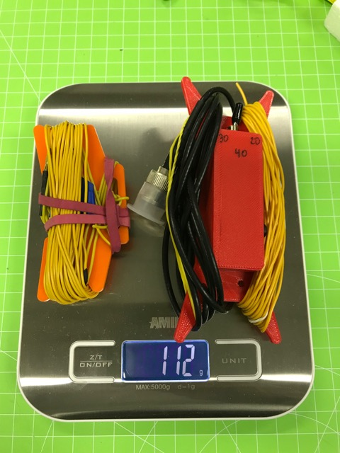
Over the weekend, I optimized my variant of the antenna design and created a custom 3d-printable enclosure and winder.

All materials and instructions are here: Superlight SOTA Vertical for 40-30-20m with Loading Coil by mfhepp - Thingiverse

The main differences are as follows:

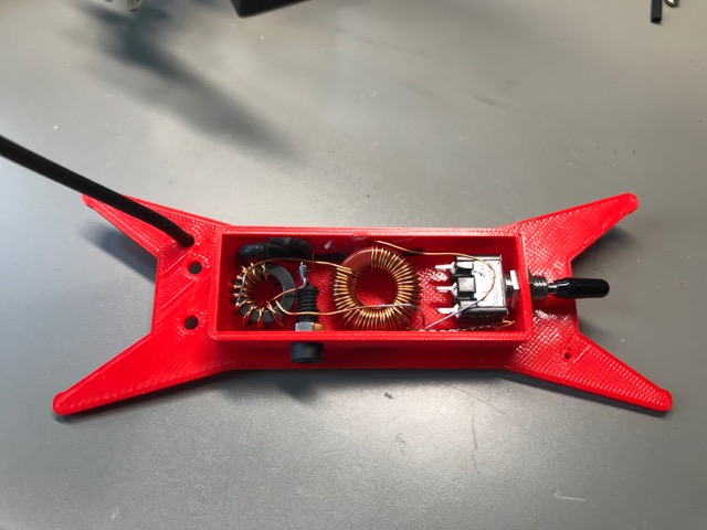
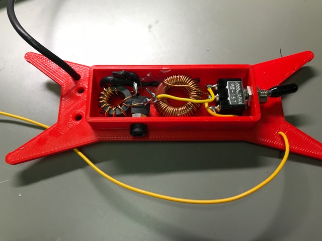
  1. I use one single, tapped T68-2 core instead of two to obtain the required inductances for 40 and 30 m.
  2. Instead of two SPST slide switches, I use a single SPDT 3-pole on-off-on switch, as proposed by Heinz, @HB9BCB.
  3. I added a common mode choke in order to reduce the effect of unavoidable asymmetries between the radiator and the counterpoise.
  4. Instead of four 10 ft. ground radials, my design can also be used with
    a) one elevated, resonant radial, tuned for each band by winding up the remaining wire, or
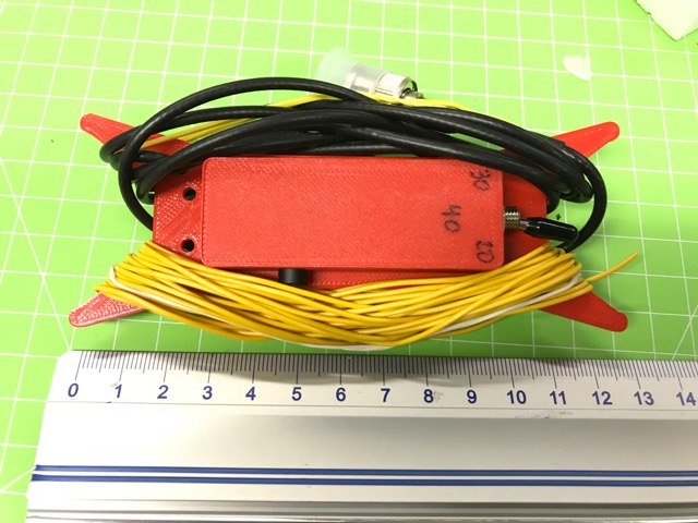
    b) three elevated, resonant radials attached to each other.
  5. The enclosure is also a winder, same as with Packtenna antennas.

I have not yet tuned this one, because it is just too cold outside right now :wink:

Enjoy!

73 de Martin, DK3IT

Edit: The details of the tapped loading coil are as follows: With 0.5mm magnet wire, wind 25…26 turns, then add a short tap, then another 20…21 turns. Leave at least 10 cm on either end so that you can adjust the tap by adding a turn on one side and removing one on the other. Now tune the loading coil with a component tester or other device for measuring inductances. The total coil should have 11.5 - 12 uH, the 25…26 turns should have 3.4 - 3.6 uH. It is important to shorten the rest of the coil (i.e. the 20…21 turns) while measuring the inductance of the lower 25…26 turns. The 0.5 mm wire fits on the T68-2 core and should be thick enough for high efficiency and QRP levels.

IMG_2622
IMG_2624


IMG_2626

9 Likes

FYI: A watertight variant of the switch is available e.g. from Amazon at

73 de Martin, DK3IT

I did the QRP-Guys (or rather the USPS) an injustice - the antenna kit has just arrived here today 5 days after they sent it. Now I have to wait for the wire I ordered for it’s driven element and four radials to come and the new on-off-on switches.

Ed.

Hi all,

as for the counterpoise, I am now considering (and hope to be able to compare) several alternatives:

a) four non-resonant ground radials, as in the original design - not so much influenced by differences in the ground, but less efficient).
b) single counterpoise on a winder with markings for each band; fine-tuning for compensating differences in ground, same as @G8ADD has proposed.
c) three pre-tuned resonant counterpoises, soldered to a single 2mm plug with no winders on the end.
d) same as c), but with a small inductor for loading a shortened counterpoise for 40m. Will make the set of cps easier to manage on a small summit. Unclear impact on performance, likely more difficult to tune (narrower bandwidth).
e) single radial with markings and a variable L-network/transmatch for the counterpoise, i.e. adjusting the resonance of the cp by a variable inductor or capacitor. The advantage is that you will need no fully-fledged ATU and do not have to retract and redeploy the cp for a band-change.

Any comments and ideas?

73 de Martin, DK3IT

Hi Andy, do you have pictures or other information about your design?

73 de Martin, DK3IT

Martin.
, i think these tuned cp ideas are worthy of experimentation

I look forward to your findings
John ve3ips

When I first started in SOTA, I made myself some resonant end-fed half waves and for the counterpoise, I experimented with lengths by having the antenna analyser attached. I was surprised to find that counterpoise elements of just an 1/8 wavlength looked good on the analyser. I saw no reason why 1/8 wave should work and I reverted back to longer lengths when actually operating. Then I bought myself a linked dipole and a squid pole and the difference was so great I never went back to the end-feds. Note - the end-feds were just being thrown on the top of hedges or into tree branches, had they been taken vertically up the squid pole, I’m sure they would have worked a lot better.

Ed.

Hi Ed,

I see your point, but I think it is unfair to compare an EFHW thrown over a few bushes with a center-fed dipole mounted on a squid-pole. With my 3- and 5-band EFHWs on a 6m mast, I get excellent results - often 17 - 20 dB around Europe, and occasionally NA contacts.

The thing about the counterpoise is IMO that in you case, i.e. on an end-fed antenna, the feedpoint has a very high impedance; thus, an imperfect counterpoise will be just okay (often just the braid of the coax). But with my proposed Up-and-outer design, the feedpoint impedance will be in the 30 - 70 Ohms region, thus the counterpoise will be essential for effective radiation.

AFAICS, a linked dipole and an end-fed differ just by the position of the feedpoint (and that traps or links will be symmetrical in a dipole and just one per band on an end-fed).

73 de Martin, DK3IT

Hi Martin,

That’s why I said, I think they would have worked a lot better on a pole.

My point was the counterpoise length of 1/8 Wavelength appearing to be good by the Antenna Analyser - might be worth trying if you have the time to see if you find the same.

73 Ed.

Hi Ed,
actually, I can already tell you that it is very different on this vertical / up-and-outer, because I tested in with the previous versions, like this one

Electrically, it is equivalent to the new design; the difference is that the loading coil is an air coil in the first version and wound on a toroid in the new design.

When tuning the first version, even 10 cm +/- make a difference. So 1/8 will not work.

What still surprises me, though, is that the resonant length for the counterpoise is typically significantly less than 1/4 lambda.

This is also equivalent to the counterpoise lengths recommended for the ATX-1080 antenna - they indicate a length of

counterpoise_length = 54 / frequency_in_MHz

But I do not understand where this formula comes from.

73 de Martin, DK3IT

My understanding, based on the statements by G. Janzen in his publication “Monopol- und Vertikalantennen” is as follows:

Monopole antennas (usually mounted in a vertical manner and therefore simply called Vertical antennas) are, as the name implies, only Half-Antennas. For these monopoles to radiate, a maximum of current must be able to build up at the base - which requires an electrically equivalent counterpart.
This electrical counterpart was/is called Gegengewicht by the German-speaking antenna experts (in English: counterweight or Counterpoise).

This Gegengewicht/counterpoise can then be realized either exclusively through the earth (Marconi antenna) or by metallic plates/roofs or radially arranged wires, the so-called Radials.

So, radial(s) is understood as a possible realization of the electrical counterpoise.

IMHO, with a little generosity, the two terms can be used quite synonymously, isn’t it?

Hi Heinz,

I believe the term “counterpoise” is an attempt to distinguish between tuned radials (normally quarter wave) and one or more much shorter conductors thrown into a design because they make an antenna show a usable impedance when without them, it doesn’t.

One of the articles I found in an archive of articles by LB Cebik W4RNL pondered the introduction of the term “counterpoise”. He eventually concluded that the term had no established meaning in antenna theory and declined to use it. He was a purist but perhaps his puzzlement over the term indicates a lack of theoretical validity.

But now, some years later, I suppose it is taken to mean lots of different things. Like many things in amateur radio, some are well supported by communications theory and some are not.

73
Andrew vk1da/vk2uh

You probably refer to these contributions by L. B. Cebik:
http://www.w5qgg.org/marc/images/stories/marc/counterpoise.pdf
http://vtenn.com/Blog/wp-content/uploads/2016/12/Inverted-L-Cebik.pdf

Indeed, there are actually about as many opinions as there are experts. Too bad that a joint meeting with all these experts could unfortunately not take place, hi.

BTW, I myself am not an expert on monopole antennas, only a few 100 out of over 28’000 SOTA QSOs were made using such antennas.

By the way, Cebik’s original Web page is long gone, but the Web Archive preserves a copy of at least a part of it:

https://web.archive.org/web/20090331095417/http://cebik.org:80/

It is incomplete, however.

73 de Martin, DK3IT