Hi all,
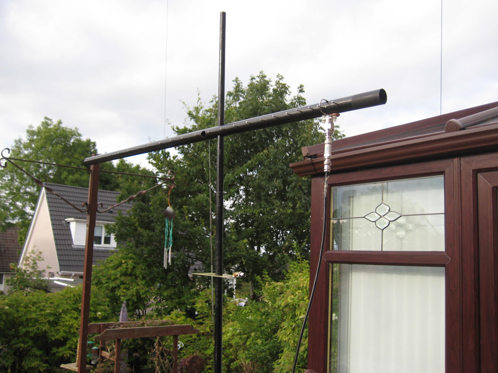
just want to share my concept for a lightweight and portable VHF Yagi antenna made out of fiberglass tubes:
Link to PDF

Feedback is highly appreciated.
73
Martin - DF6MH
Hi all,
just want to share my concept for a lightweight and portable VHF Yagi antenna made out of fiberglass tubes:
Link to PDF
73
Martin - DF6MH
Great idea!
Thats really lightweight!
73 Armin
Hey Jack
…wasn’t that your hallstand? 
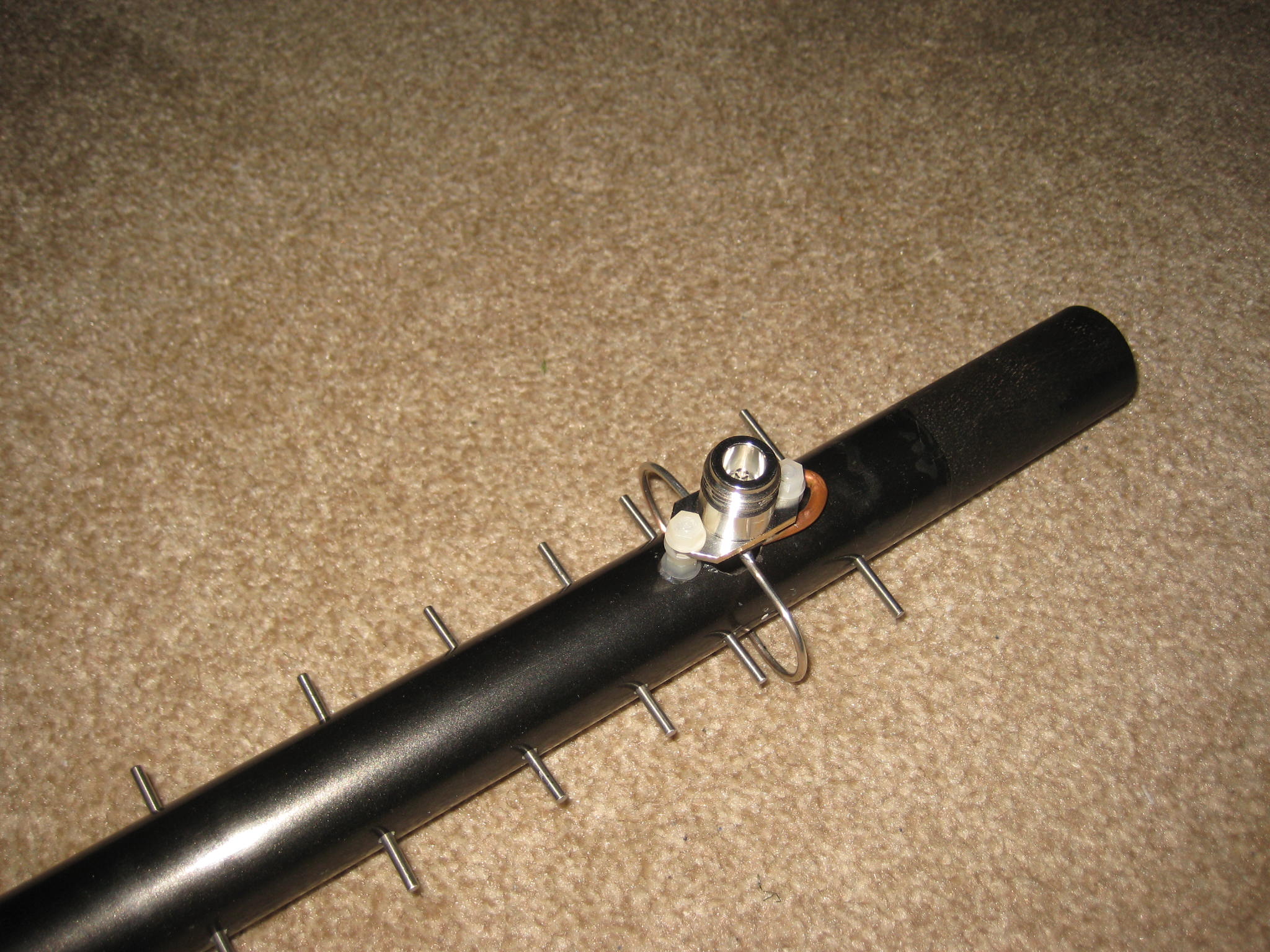
looks funny - but the elements are well fixed!
73 Armin
A very interesting and well delivered document Martin, thank you for sharing.
73
Tim
G4YTD
Thanks Armin and Jim!
@GM4COX 13 cm is cheating  But really nice element to boom fixation. What about the electrical influence of the fiberglass on the resonance frequency and pattern of your 13 cm antenna? Did you have problems? This was a big topic in my design.
73 de Martin, DF6MH
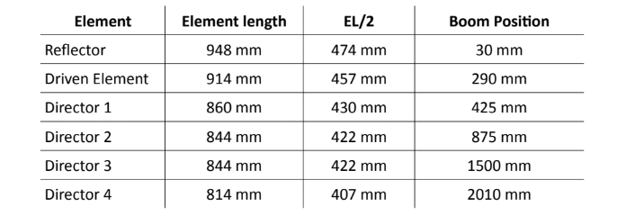
Yes - your Elements are extremly short! Did you determine the dimensions in the experiment?
73 Armin
Hi Armin,
the capacitive loading of the wire coating and the fiberglass tubes around the wire are the reason for that short length. It’s a factor of appx. 0.92 compared to common YAGI designs.
I determined the element length by simulation using CST, a professional EM field solver for antenna design. NEC based simulation tools can’t deal with dielectric materials.
There’s a whole chapter in the pdf - “Discussion on electrical design”
Maybe that answers some more questions.
73
Martin - DF6MH
Looks nice. Great photo.
I have a 2m dipole which I taped onto some fibreglass rods to make a horizontal dipole. For resonance on 144 I found it needs to be shortened a lot, 50mm each end, compared with its length when attached to PVC conduit tubing.
Another antenna, the half wave vertical, made to the correct length, was resonant on 129 MHz instead of 146, when taped onto a fibreglass pole. But when taped onto a different pole it is resonant on 146.
Conclusion: we need to be aware that fibreglass and pvc materials vary greatly in their dielectric constant which affects resonance. They also probably vary in the amount of power they soak from your antenna. I have not measured that. But I think if resonance is affected, losses and efficiency are likely to be affected too.
Measurements made with an AA600 analyser.
Andrew VK1DA/VK2UH
Hi Andrew,
thanks for reporting your experiences with dielectric support materials!. There is an influence, no doubts.
I’m quite sure that losses are no big issue as the electrical field is still mostly concentrated in air and not in the lossy dielectric material. Fiberglass is also widely used in professional antenna designs without being known to produce too much losses.
More losses than produced by the loss tangent of the fiberglass material will result from the thin wires and the skin effect.
Regarding the resonance frequency:
In Literature you most often find an epsilon_r value of 5 for fiberglass material. In PCB design you calculate with a value of 4.5 for FR4 which is pretty much the same. The actual value depends on the ratio of filament to epoxy parts.
I varied e_r of the fiberglass tubes from 4…6 in simulation. That resulted in a frequency shift of appx. 0.8 MHz per 1 change in e_r. I think that is tolerable. If you build the antenna a resonance is slightly wrong, you also can correct it by linearly scaling the element length by some cm without affecting the pattern too much.
I know this design is quite new and there are some challenges and uncertainties. Somebody needs to rebuild it and report from his experiences. Then we’ll know better
73 de Martin - DF6MH
Hi Martin,
Thanks for the additional information re the characteristics of these materials.
In the first of my examples, the fibreglass rods were tent poles purchased from a camping shop as replacement poles for dome type tents. I think they are 8mm diameter. There is no detailed technical description on these poles.
In the case of the two poles used to support the vertical antenna, both were very lightweight poles which collapse to about 75-85cm, to be carried in the backpack. Of the two poles, the one labelled “carbon fibre” is the weaker one and does not affect the resonance of the antenna. The other pole is slightly stiffer and I suspected it of having carbon fibre in its construction as it did have a large effect on the resonance. In other words the labelling appears to be misleading and incorrect. Both were purchased from chinese sources on ebay or aliexpress. Who knows whether the chinese labelling was originally correct and the problem may be in the translations.
It is a reminder that all labelling on inexpensive items is to be treated as suspect until proven otherwise.
73 Andrew VK1DA/VK2UH
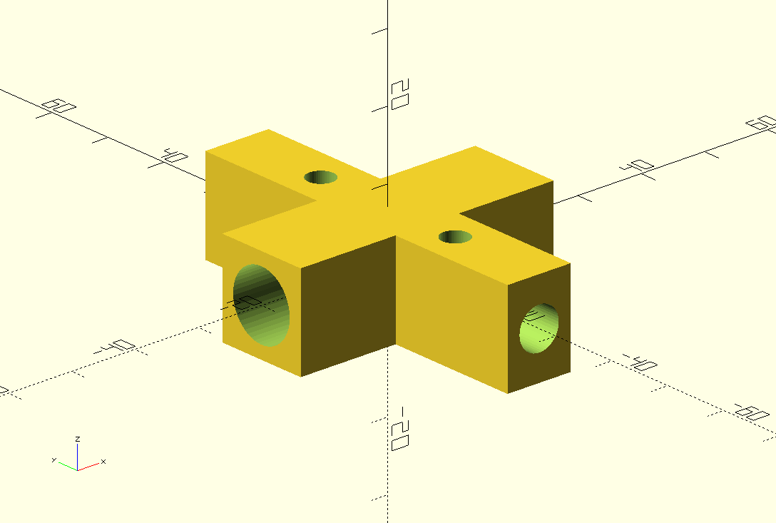
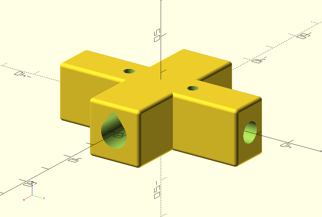
Great idea, maybe joints can be printed on 3D printer and building will be much easier. I will think about it.
73 Ondra OK1CDJ
Hi Ondra,
yeah, thanks for this nice drawing. I also thought in this direction but I have some doubts that a home-printed part is strong enough.
A colleague at work proposed selective laser melting of aluminum powder for this. He thinks that might even be cheaper than to mill and drill the crosses. He knows some Chinese manufacturers for this process and would help me. He said that makes sense beginning with around 100 parts.
73 de Martin - DF6MH
Hi Martin, just ordered Fiberglas parts in local model Hobby shop. I think that 3D printing will be ok. I made many antennas with 3D printed parts. We will see…
73 Ondra OK1CDJ
OK, Ondra, wish you good look and hope to see some pictures soon! Just contact me or write here, if you have questions or suggestions on the rest of the design.
73 Martin - DF6MH
I am finding difficult to make 45 deg cut and make inserts to the to boom. I will try another method how to fix boom in axial position. Here is final joint ready for print:
Material come during next week.
Which kind of insulation have your wire ? PTFE or PVC ??
73 Ondra
Looks interesting, Ondra. Will you glue something onto the end of the boom in order to fit into your printed part?
Isolation of the cable I used is PVC:
Here is a link to the Datasheet:
73 Martin - DF6MH
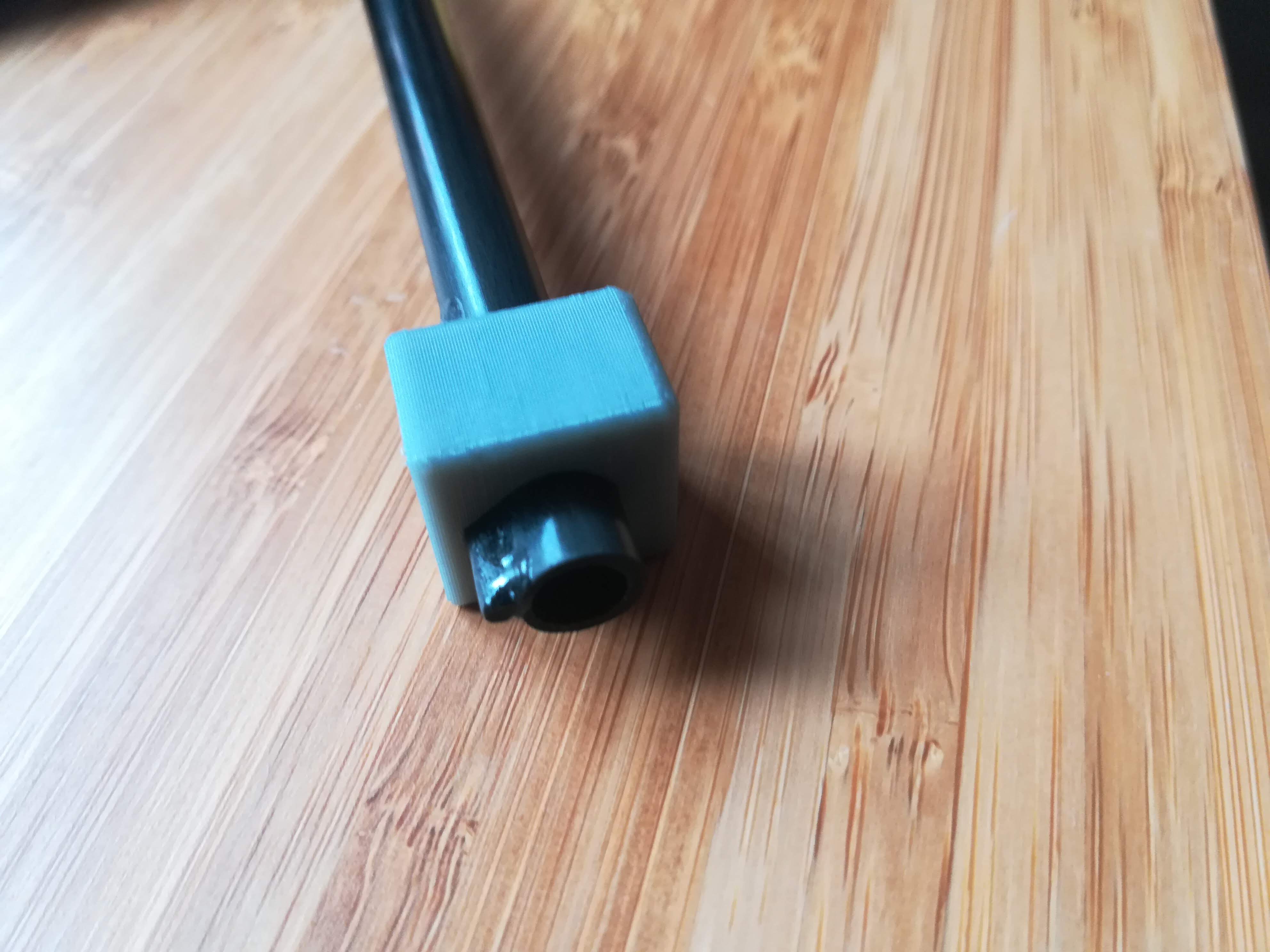
Today come my glass fibre and carbon material (30 EUR). I thing 3D printed joints are strong enough. Maybe can be lighter in next version.
I am using carbon tube for boom and there is piece of 2 mm carbon rod glued on the top. I printed helper to put it exactly on the place.
73 Ondra
Carbon conducts electricity! - I think: It will be totally different than glass fibre
73 Armin