EFHW LC Matchbox

EFHW Matchbox

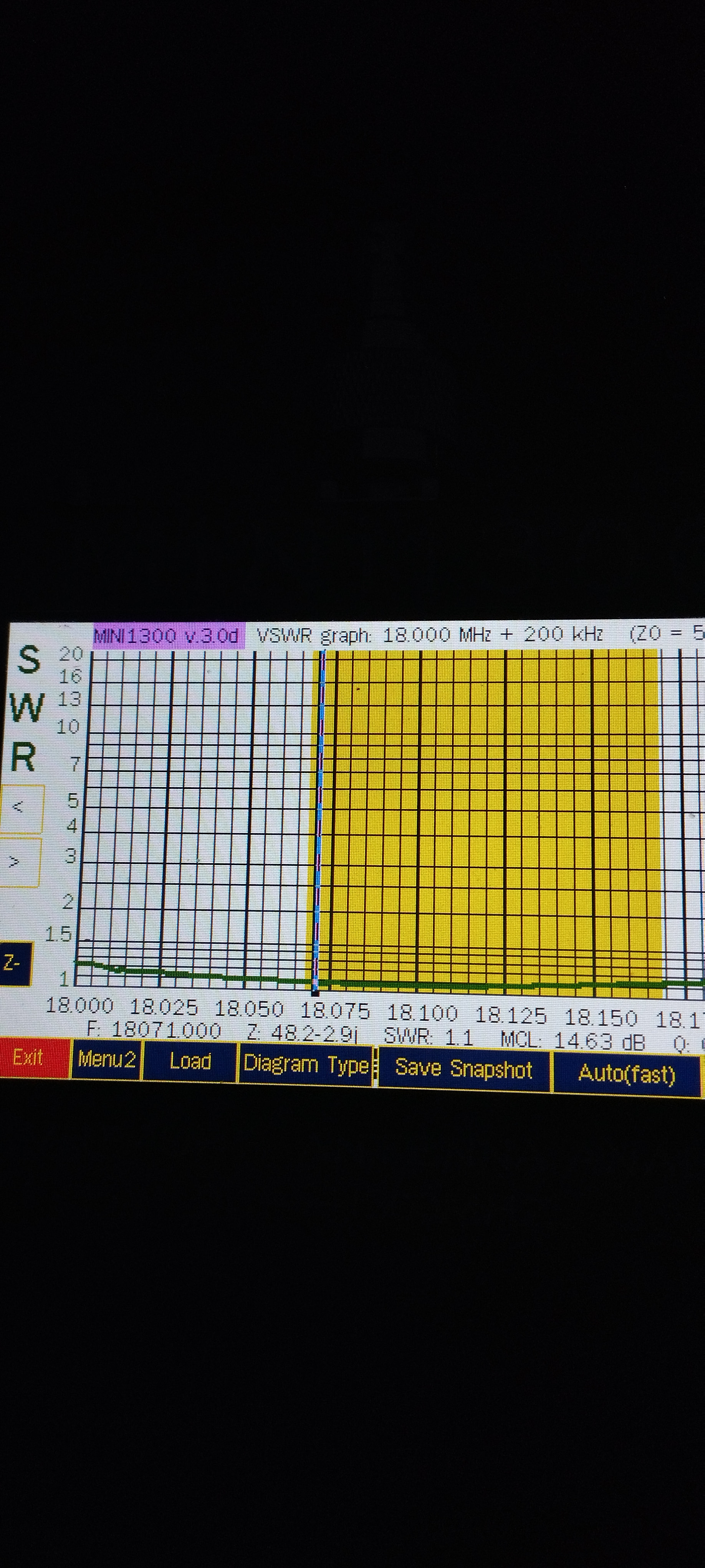
The purpose of this post is to share the efhw matchbox I built, and the SWR curves I obtained.

I commonly use a shortened efhw antenna. My 10/20/40 antenna is made of #10 m wire, followed by a #25 microH coil, -acting as a choke on 20 and 10m- , followed by # 2m wire. This antenna is working as a half wave on 20 m, a full wave on 10 m, and a shortened half wave on 40 m.I also have a 10/18 MHz antenna working using the same concept, haff wave on 18Mhz, shortened on 30 m.

I usually feed my antenna with a 81:1 balun, to “adapt” the high impedance antenna to the 50 ohms impedance of the transceiver.The impedance varies with the height of the antenna, the soil, the antenna configuration, etc- The impedance is different for each band.The 81:1 transformer response is not “flat”. The impedance matching is “acceptable for all bands ”, but far from perfect, and varies.

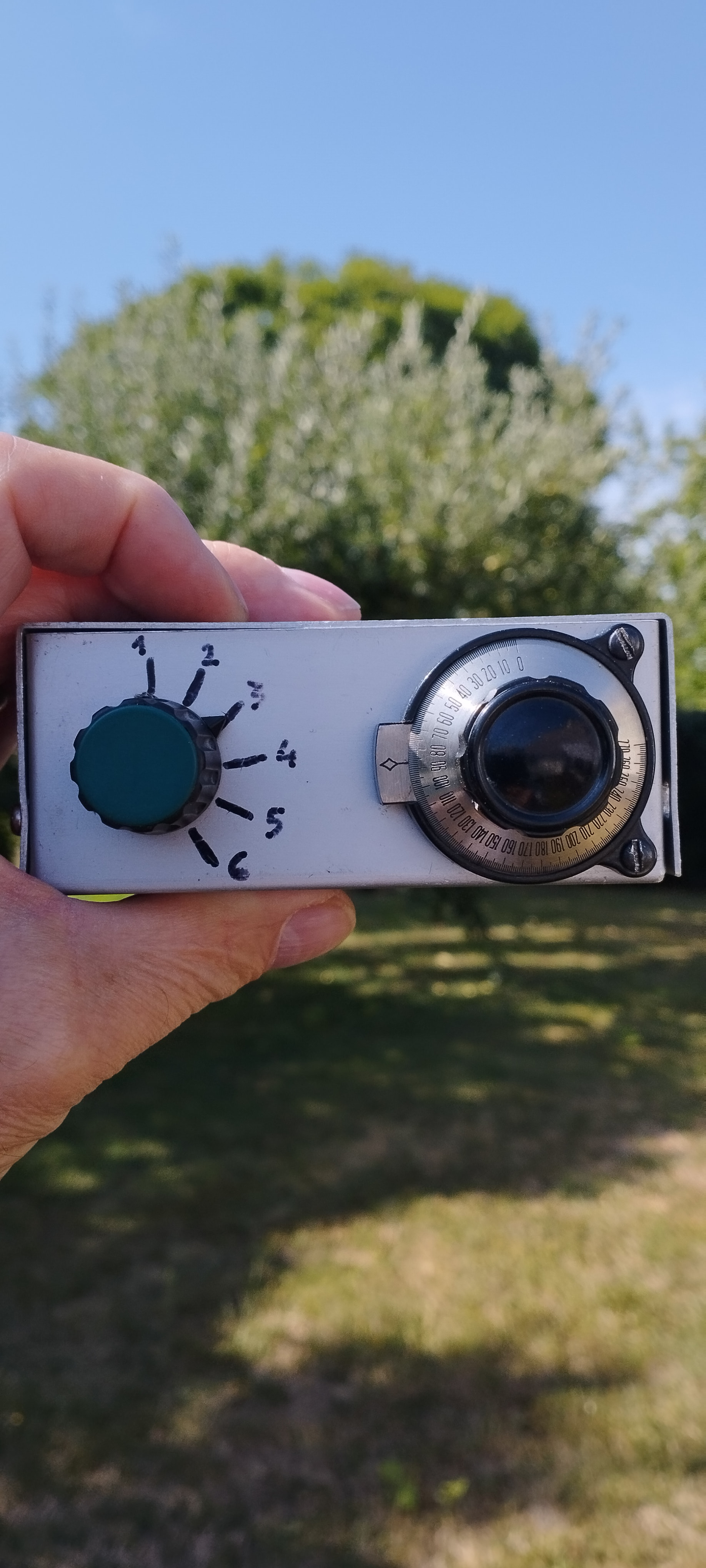
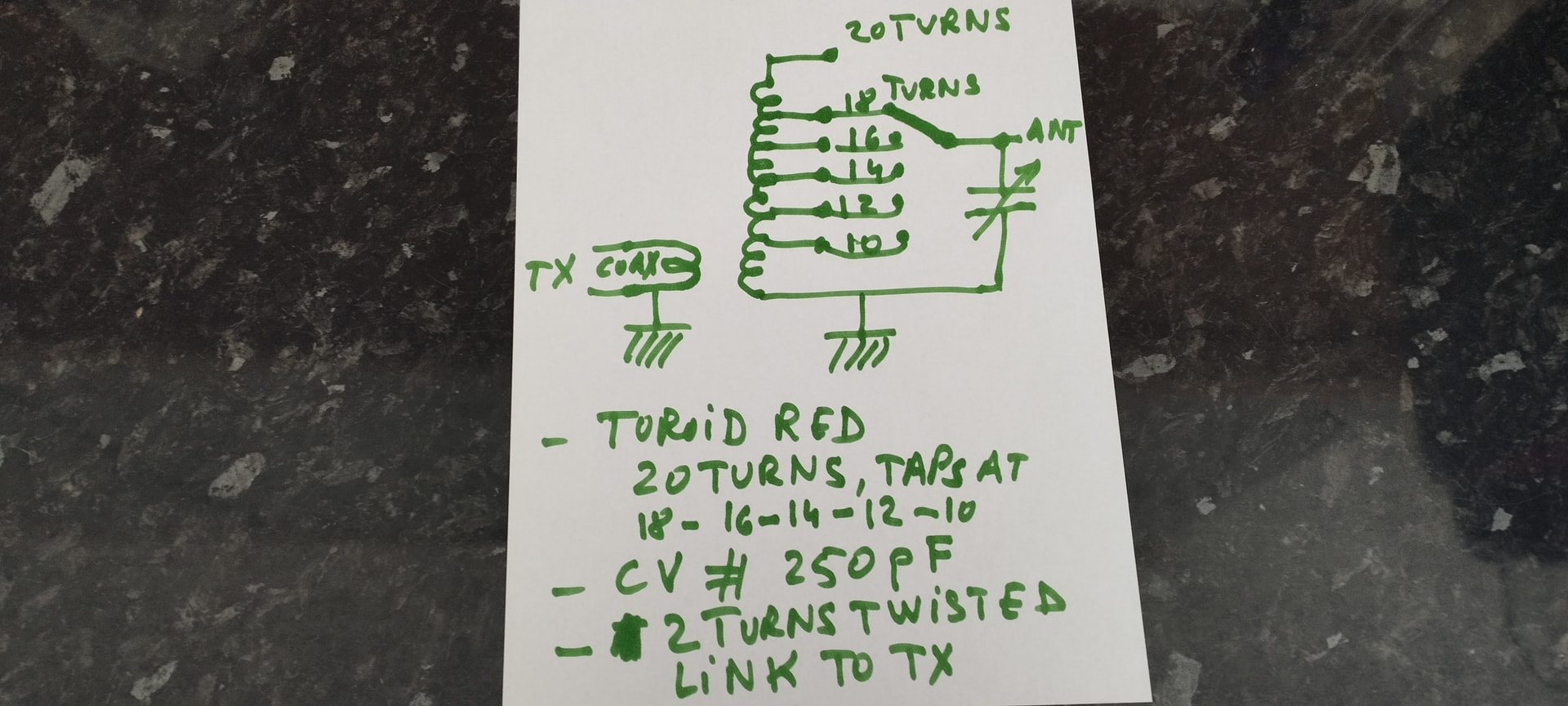
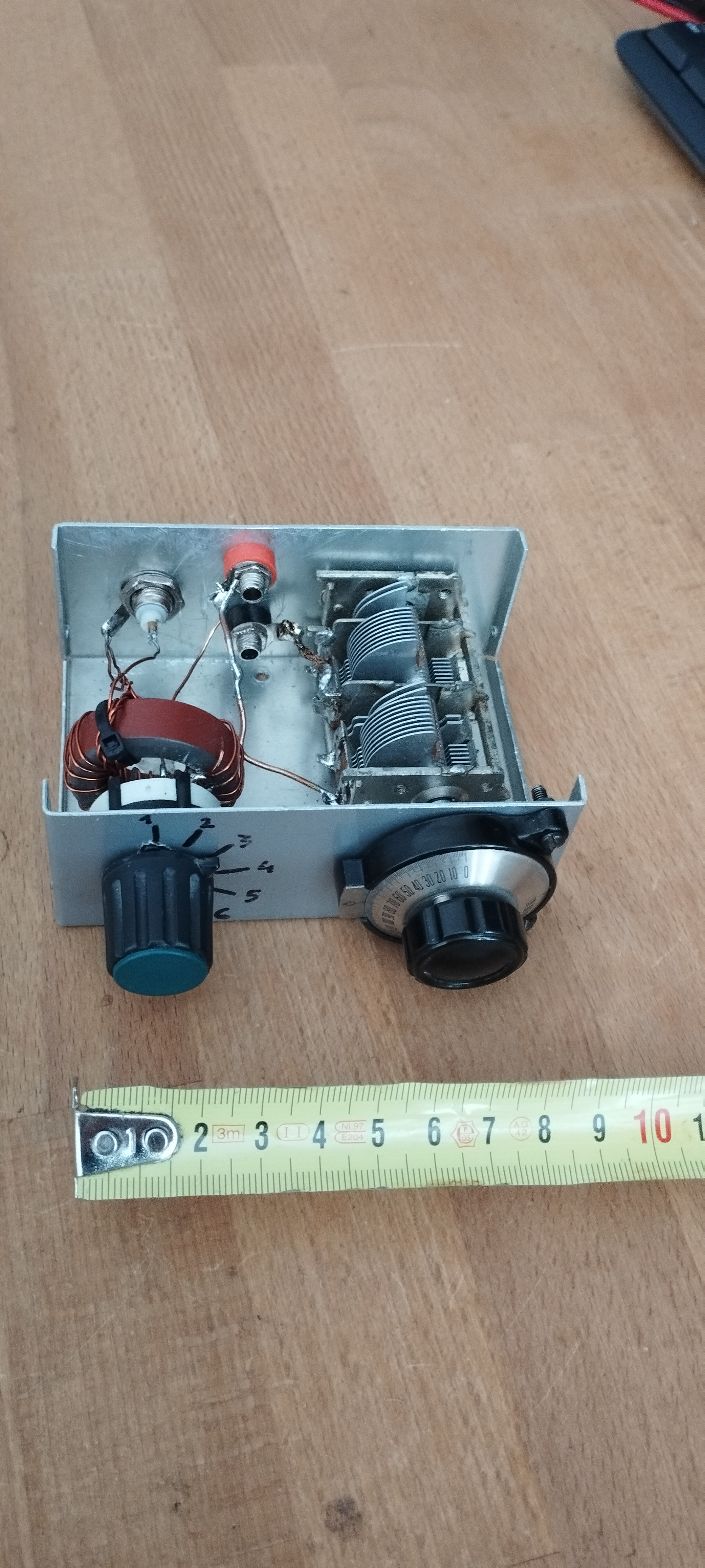
I wanted to explore the possibility of an “impedance matchbox”, for better matching. As an impedance matching circuit, I essentially built a parallel resonant LC circuit, which has a high impedance when tuned to resonance. On the TX side, this high impedance is “transformed” to adapt to #50 ohms.The circuit is simple. A toroid (red, I believe T130-2 or T 150-2), a variable capacitor,# 250 pF, a few connectors, a box. For the convenience of the settings, I used a multi-turn vernier adjustment knob, and a 6 positions switch, to select the best suitable tap on the coil. Everything was available on hand, in my drawers,

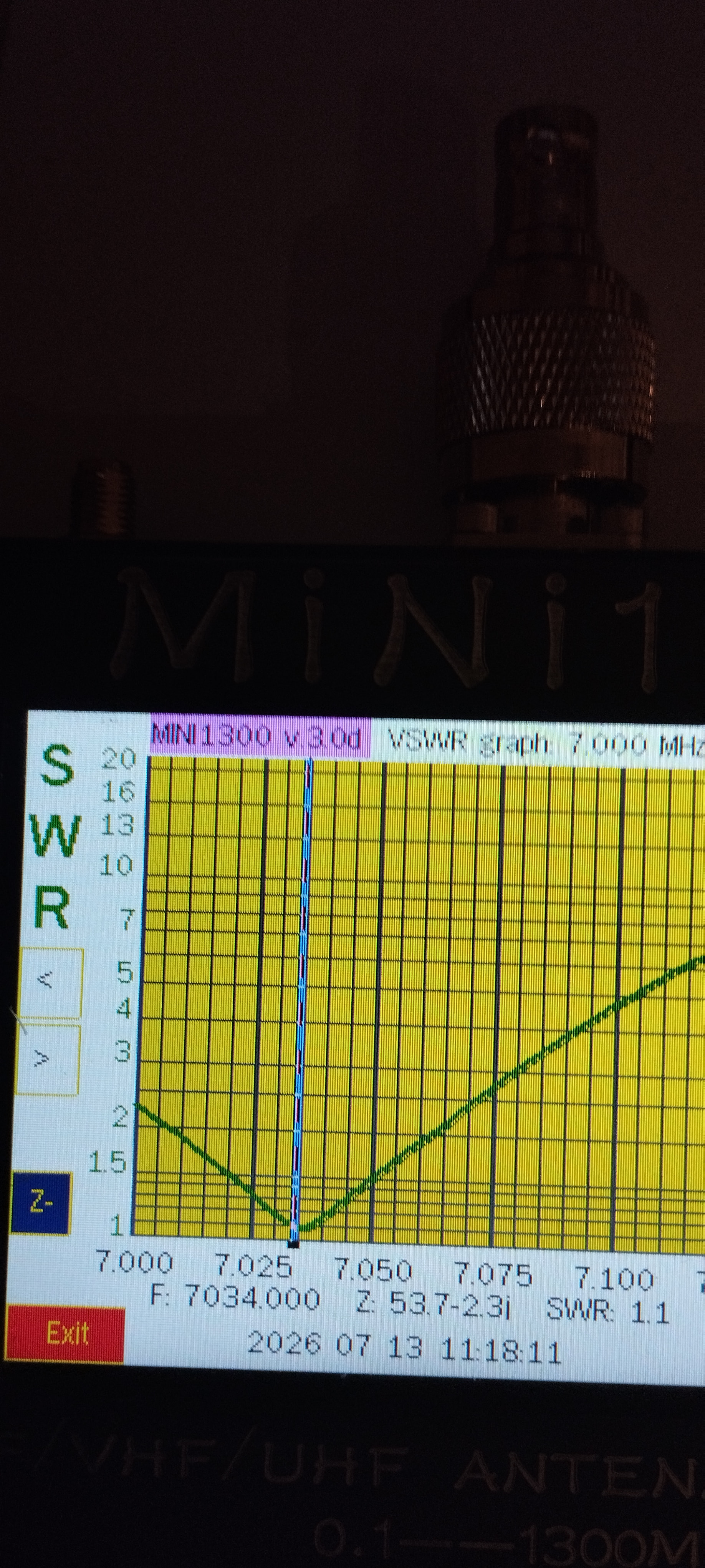
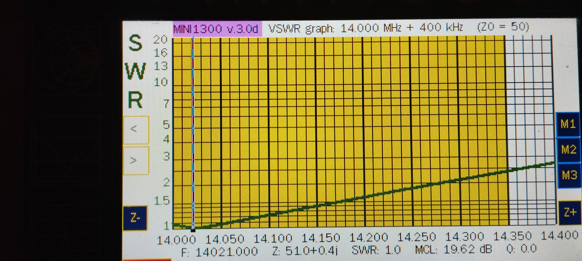
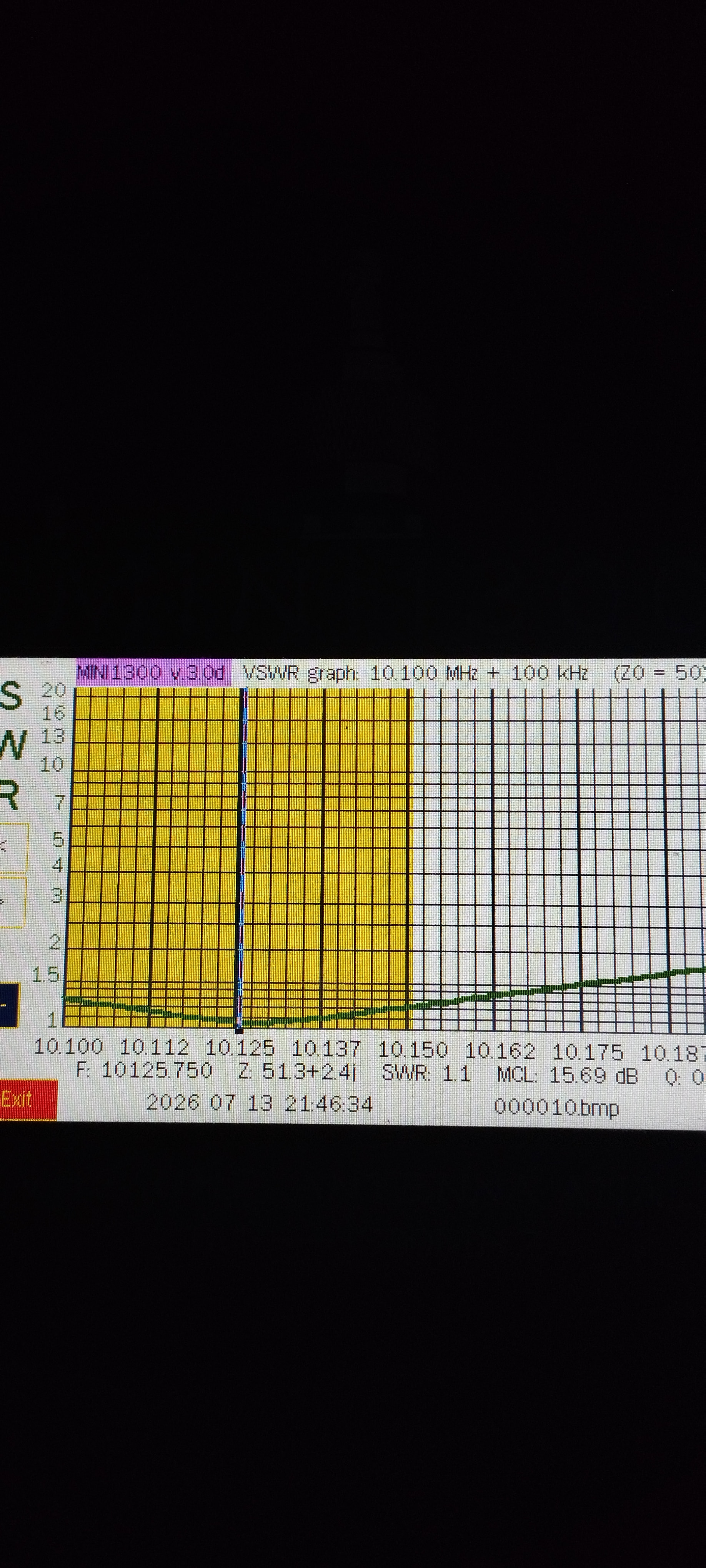
The adaptation was initially checked with my mini 1300 antenna analyzer. Of course, the range of the adjustment of the matchbox will depend on the components. essentially L values/range, max capacity, residual capacity. My matchbox is usable with efhw antennas, from 40 to 10 m, for an impedance discrete range of # 1000 to 5000 ohms, with SWR < 1.5, most of the time lower than SWR 1.2

To use the matchbox, once the best tap is selected for a given band, just adjust the capacitor for max signal/noise, by ear, or visually on Smeter…and transmit. The matchbox is less convenient than a broadband transformer, since you need to adjust for each band, but it is very fast to do. The circuit has really high selectivity, nice for RX, and gives a much better impedance adaptation vs a broadband transformer. Yield, efficiency … .I do not know how to accurately measure, so I won’t comment. HF contacts really work well with qrp power.

73 / 72 de Pierre F5MOG

A few pictures below, schematics, the matchbox, SWR curves obtained in my garden, using the above described antennas, installed as inverted L, about 5 m vertical, the remaining part horizontal.
13 Likes

I’m curious, what made you think you needed one?

A decent EFHW transformer will give you an SWR below 1.5 on all bands with 80–90% efficiency, needs no tuning, and weighs only a few grams.

I’ve always wanted to build an LC tuner just for the fun of it, but broadband transformers work so well that I never took the plunge. I was given a Z-match tuner (ZM-2), but I’ve never used it. Its efficiency is quite low, and you have to keep tweaking the knobs all the time. Maybe I’m missing something :face_without_mouth:

1 Like

Why you’d - well, just me - want a simple LC:

35ft wire no coils - covering 5 bands for QMX with good efficiency - wire at any height/config, including lying on a bush/rock…

5 Likes

I agree with Peter. I have evolved into two /p antennas- a) an EFRW and a 9:1 impedance coupler (58 ft max, with insulation colour changes at “nice” shorter lengths (28’, 35’, 41’ in case space is limited). Mostly set up as inv L; or b) 2.5 m whip on top guyed hiking pole with dedicated collapsible spring wire capacitive hat, plus 1 to 3 raised radials. For set ups with no trees.

Both fed by 4 m RG174 coax to an L-match tuner. This has switchable decade inductors to get just the indictance you need and a 270 pF polyvaricon capacitor. A switch gives LC or CL configuration to match type if antenna.

That little L-match gives me wide flexibility of bands and antennas from 40-10 m, and has low insertion loss (0.5 dB typical).

One could get lighter but, hey, I like turning knobs and flipping switches!:smiling_face_with_sunglasses::+1:.

Best 72, Scott VA7SNJ

7 Likes

… me too :slight_smile:

my QRP L-tuner tunes a 20m wire and a counterpoise on all bands from 60m to 10m. No links nor traps required. The configuration (inv. V, inv. L, wire on rocks/bushes, …) doesn’t matter.
It is the first choice for any activation on HF. All my EFHW transformers are retierd unless I want to squeeze out the last few grams :wink:

Inductors are 0.5 / 1.0 / 2.0 / 4.0 uH and can be shorted individually
Capacitor is about 100pF

73, Roman

8 Likes

Good work Pierre,

LC tuners work very well with endfed wires.

I personally would not carry one to a summit as I think I have got a pretty efficient EFHW I made a few years ago. Generally average 15 QSO per activation with that antenna both local VK’s on 40/20m DX to JA on 15m CW and DX to EU on 20m with aternoon long path.

My transformer is wound on a SOTAbeams toroide with a TDK capacitor and 2m counterpoise as part of feed point end tie off cord. . 3m RG174 coax with another small 43 mix toroide wound as a choke/balun near the feed point before I soldered on the BNC coax conector for my KX3.

But if you are happy to add an LC tuner to carry up summits as part of your exercise/SOTA plan knock yourself out old Mate.

Regards Ian vk5cz ..

3 Likes

Thank you posting all the details. I wish I had the knowledge required to do the same and will keep learning (as we all do). Little posts like this add to that bank of understanding and interest.

For those not understanding the practical requirement for the device, I suspect that misses the point which is the fun and interest of the build.

3 Likes

Hello all

Interesting string here, for sure. It struck me that the matching circuits presented here fall into two camps - a parallel LC pair with tapped inductor and link coupling, and a “direct through” L-match topology with switchable decade inductor with variable cap before or after the inductor. We can build these large or small based on power we plan to use and weight we can tolerate carrying using hefty toroids or air variavles, or smaller components.

But some general questions come to mind:

  1. How does insertion loss compare across say 40 - 10 m bands for these two topologies?
  2. What benefits does link coupling offer compared to direct-through arrangement?
  3. For QRP, what are the smallest toroids and wire gauge that would perform acceptably well for the classic decade-switched L-match? It may be that the compact switched L matches could be made even smaller and more compact (think if the toroid density in a QMX). At some point, I’m thinking a match circuit could work electrically but be too small to practically use in the field.

Finally, I recall the “Rock-o-nator” matching circuit devised by QRP Hall of Famer Charles “Rock” Rockey W9SCH (SK) which was a link-coupled parallel LC circuit that could be switched to a series LC circuit with DPDT switch. He used plug in coils for high or low groups of HF bands, 1930s style. What’s old is new!

Best 72, Scott VA7SNJ

3 Likes

How small and light for the L-match? See picture. Toroid size 37, mini DPDT, 56g. QMX in carbon-reinforced case, 150g. Total SOTA stuff under 400g.

7 Likes

Two solutions to a simple problem

And a carbon fiber case

John ve3ips

2 Likes

Very nice, Peter. All your builds are well done and look tough as nails. That’s probably as small as practical, especially if windy, gloves, etc. Love those knurled knobs but I am using banana plugs. I’m guessing the “C” switch toggles between CL and LC configuration? Have you measured insertion loss across HF bands?

Great stuff! Scott

1 Like

Spaceweather writes today: “… sunspot 4493 is complexifying…” – would it therefore be permissible to write that the antenna matching box of HB9EBE is “simplifying”? :sweat_smile:

At first glance, it does indeed appear practical and reduced to the essentials.

Well done, Peter!

BTW, insertion loss is typically <0.15 dB (efficiency ~97 %) measured with very short wiring (inductors at the switches!).

2 Likes

Thank you for the flowers, Heinz and Scott! It’s indeed my latest and probably last model - as light and as small as it gets while remaining practical. No choke any longer, as it does not seem to make a difference in my case. C switch to go from LC to CL indeed.

The efficiency of this model I have not measured; it’s predecessor was around 95% if I remember well, corresponding to around 0.2 dB loss. That’s all in, as there is no coax and no step-down transformer.

2 Likes

Every topic has his own life and sometimes it turns into oposite direction.

It started by info about parallel tuning circuit into discusion about LC tuners.

I never used LC tuner with efhw. But I used parallel circuit with efhw and it works perfectly. I also used parallel circuit tuner with 1,4 and 2,5m telescop and two radials. It also worked perfectly. Search for gawant antenna. Also, VK3ye used parallel circuit for his pedestrian antenna

What kind of tuner is better? LC or parallel circuit? I don’t know but maybe discussion will tell

The shot was obviously fired a bit too quickly, because even the most efficient broadband transformer is overwhelmed if the antenna is too narrowband and/or its resonant frequency is slightly off.

In such cases, users of broadband transformers often carelessly press the ATU button (if available) – which unfortunately does not eliminate the impedance mismatch losses at the input of the broadband transformer; it is therefore merely a deceptive improvement.

1 Like

Yes, the parallel tuner is great for whips! It’s my standard tuner for the 2.5m whip, and gets decent results even at 40m. Never occurred to me to use on efrw or efhw as the L-match is so efficient…

2 Likes

I never carried a tuner on SOTA so far, and never experienced SWR higher than 1.6 I think.

Anyway, I orderered a nice variable air capacitor, I also want to try :grinning_face:

2 Likes

A while back I built the EFHW link coupled tuned coupler by Steve Yates AA5TB. I started using this with a 10m wire as an EFHW on 20m. It also tunes a 20m wire for 40m and other bands.

I like to hear the nice sharp peak in band noise as I tune through resonance. It gives me an audible confirmation that the antenna is tuned and all’s well.

6 Likes

Here is my version used in the QMX Carrot.

73 Chris

2 Likes

I made one of those a while back and used it with a 5m wire and my 817. Worked very well. It would tune up the 5m wire on 12 and 15m and obviously 10m. I have no idea what the efficiency was but I made QSOs with no great problems with it. I left the matchbox on the summit Torlum :frowning:

I have since made another which I use with an old hamshop.cz trapped EFHW for 20/30/40m. The original match unit got really hot on 40m so out of the junk box came another unit. That works fine and matches the trapped EFHW on 40/30/20. It can’t match on 17m but there is a now a physical link at the 17m 1/2 wave length, open the link and it matches on 17m. And 15/12/10m. Again I don’t know how efficient it is. I only use it to match the trapped EFHW on 20/30/40 with my QCXs now. The trapped EFHW is used with a broadband 1:49 or 1:64 using a Fair-rite '5002 core with my KX2 +ATU. Again no idea of efficiency but it makes QSOs.

ODX using the AA5TB unit and a 20m QCX is 12500km from GM to YC (Indonesia).

4 Likes