Thanks everyone for the answers. Much appreciated.
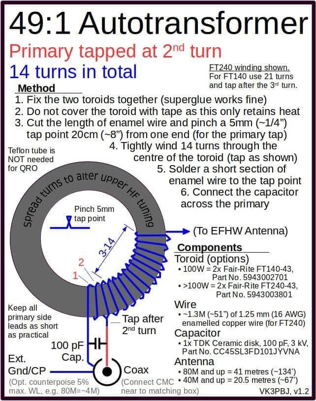
I will try the autotransformer method over the weekend and report back
Thanks again.
Peter
Thanks everyone for the answers. Much appreciated.
I will try the autotransformer method over the weekend and report back
Thanks again.
Peter
Except you haven’t followed it. You have your windings swapped. It’s so long since I did all the theory behind transformers at uni (44 years) I need to stop and think if swapping the phase makes a difference.
Please could you expand on that? I will watch the video again tonight.
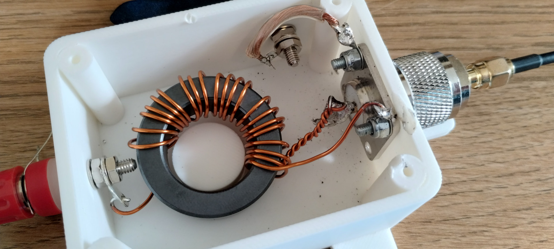
The start of the wire goes to the centre, the twist (on the third turn) to the ground, and the end to the antenna.
Thanks
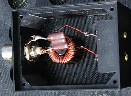
You have the twisted tap connected to earth and the start connected to the SO239. Swap them over. Start winding goes to earth, tap goes to SO239 centre.
Good spot. I will swap them around. I can’t imagine it making a difference as they are bridged by the capacitor anyway. However, I’m a newbie where construction is concerned, so will definitely try it. It’s good to be accurate anyway.
Thanks
It is making a difference. The référence is now at turn n°3 , so you have a 3/18 transformer instead, I would say. The transformer is now suited for 50x(18/3)^2 = 1800 ohm instead of 2450.
And since the two windings are not close to each other (it’s now 18 turns on one side and 3 on the other side of the tap) , the coupling between primary and secondary is terrible.
Thanks. I will try over the weekend.
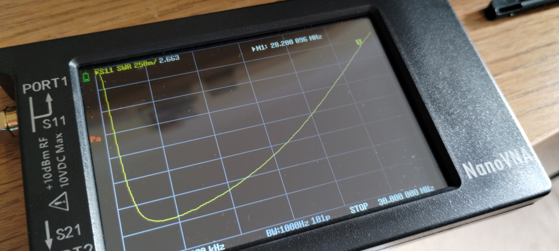
OK, so I changed it over. The start is now to ground, tap is to the SO239 centre. No difference at all, but looking above it seems like someone else had the issue with the 3:21 ratio on higher frequency bands.
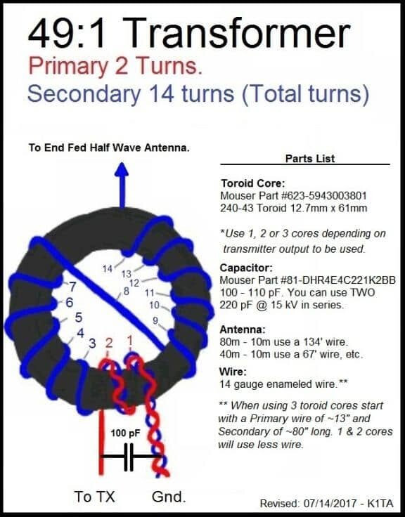
This post suggests that 3:21 is better than 3:14.
Anyway I will experiment, and also attach a wire so I can real world test. Thanks everyone.
I’ve only had my license for three years, but I’m determined not to be so much of a pre built off the shelf buyer!
Weird. Many people, including me, are using this exact same core and 3/21 to 3/24 ratio and it’s working great.
The capacitor is usually improving the SWR on the higher bands, and now it’s missing. Is it the same with the cap ?
Certainly is!
Yes, the capacitor made no difference. I will leave that EFHW as it is, and build another to the standard autotransformer method and see how I go.
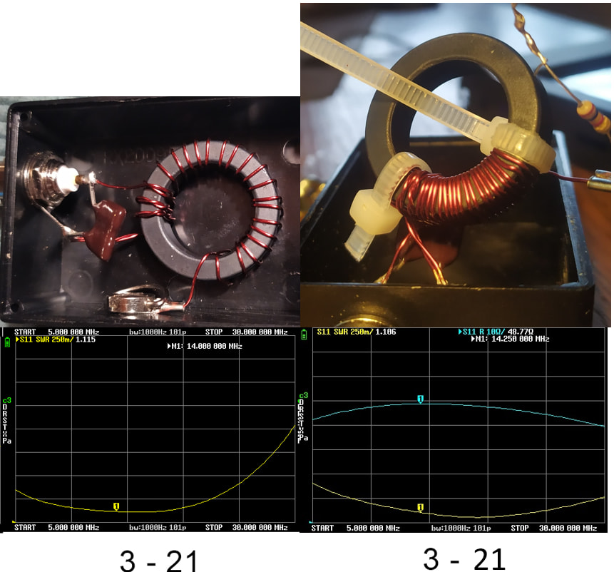
Having the wire tighlty winded around the core improve the transformer. Any change in geometry can lead to rather different curves. I experimented for way too many hours on this a few years ago and just as an example, this is what you can expect from small changes on the winding pattern:
Smaller wire can also help, I get the best results on the 2643625002 core using 0.4mm wire :
The one thing that hasn’t been mentioned in this thread is what the ratio means!
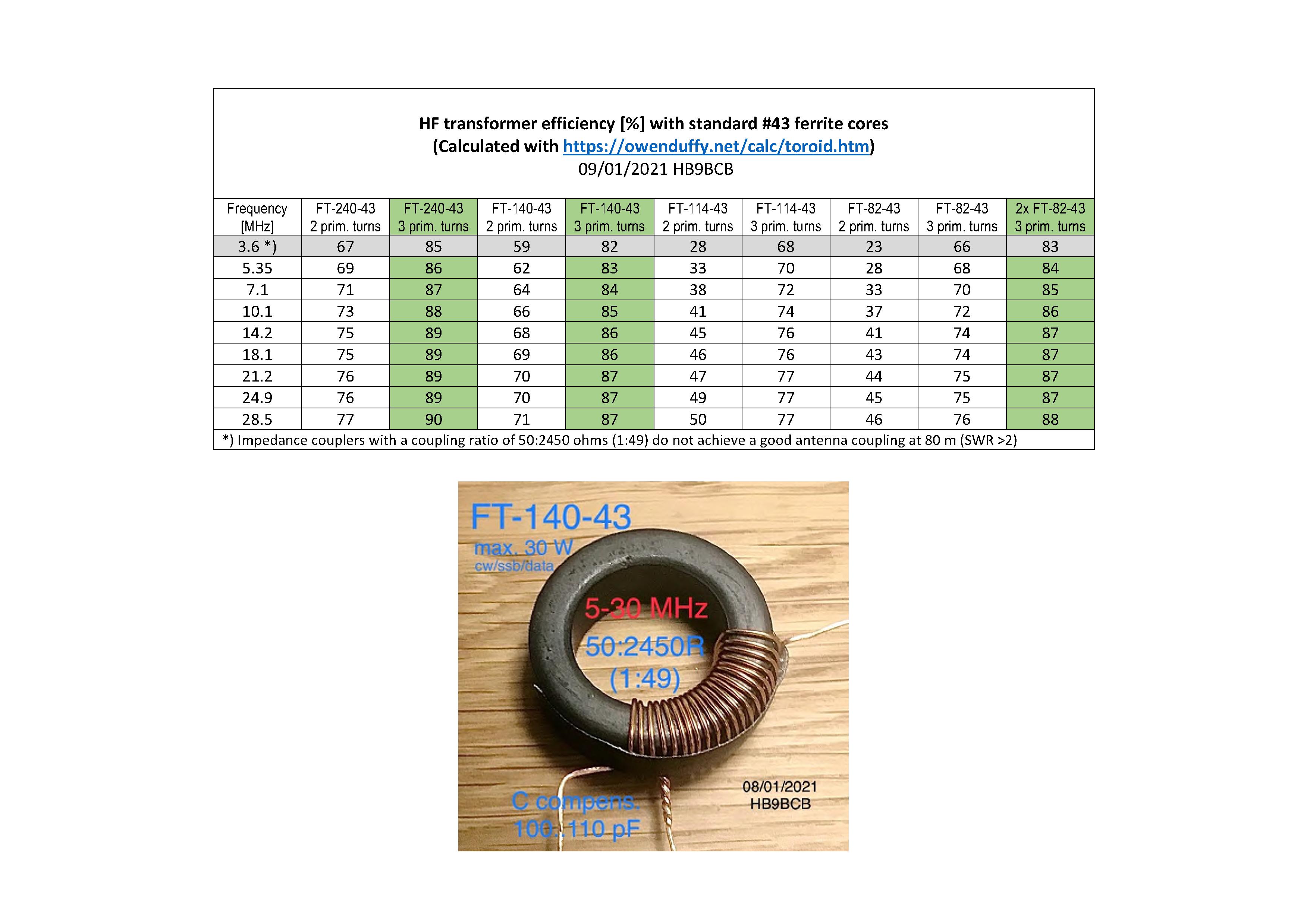
3:21 turns is 1:7 - that represents an impedance ratio of 1 squared to 7 squared which is 1:49. With a 50 Ohm input that assumes the antenna (or the resistor you are testing with is 50 x 49 = 2450 Ohms.
3:24 is 1:8 which implies that you are trying to match 50 ohms to 3200 Ohms.
It’s not uncommon to see 1:9 which implies 50 Ohns → 4050 Ohms.
So the real question is “What is the actual impedance of the antenna wire when it’s up in the air and you have a counterpoise connected to ground”?
Exactly. That’s why I made my latest one with 3 taps, then I can select the ratio depending on the conditions. I think I have 3/21 , 3/24, and 3/26 or something like that.
Sometimes , when the deployment of the antenna is a bit unclear, and so is the impedance, (angles off, bad ground, whatever …) it’s handy to be able to change your transforming ratio just with a banana plug.
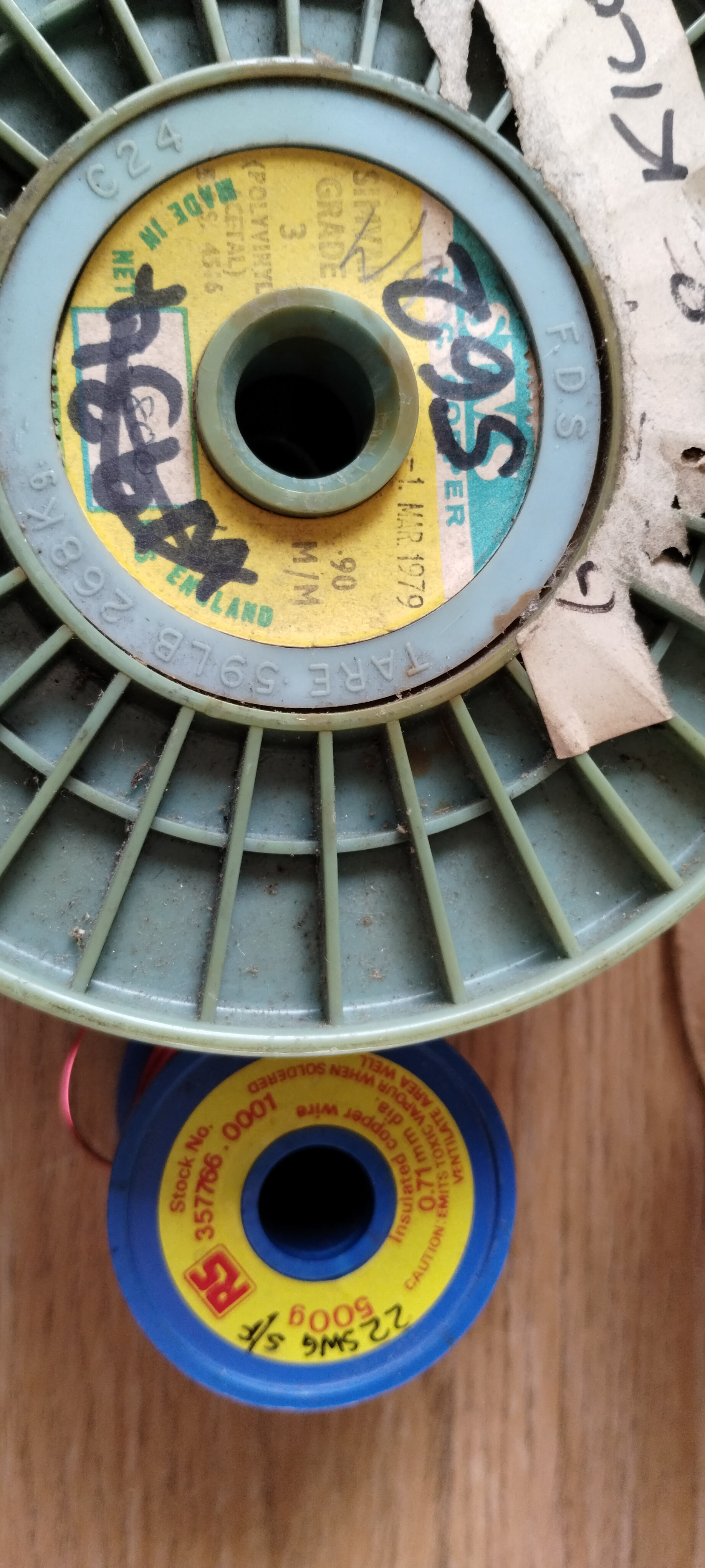
Thanks. I used .9mm wire on that one, but I also have some .7mm which I’m guessing will still be OK for intermittent 100w SSB?
On your first core, did you try moving the turns closer together, and did it make any difference?
The first picture is actually two pictures of the exact same transformer. First one with the turns apart and second one with the turns closer. And below is the corresponding swr curve.
Thanks. So closer was much better.
Would you mind me asking a slightly unrelated question? Why in diagrams are the Bifilar Wire versions always spread out around the toroid, and the autotransformer versions tightly squeezed on one section?
I’m not asking my question very well, but is it always the case that we should follow those winding examples?
Tights turns, close together, is usually more efficient. I think the second model is popular because it allows the connector to be on the opposite side of the box for a convenient design, but maybe a bit less efficient ?
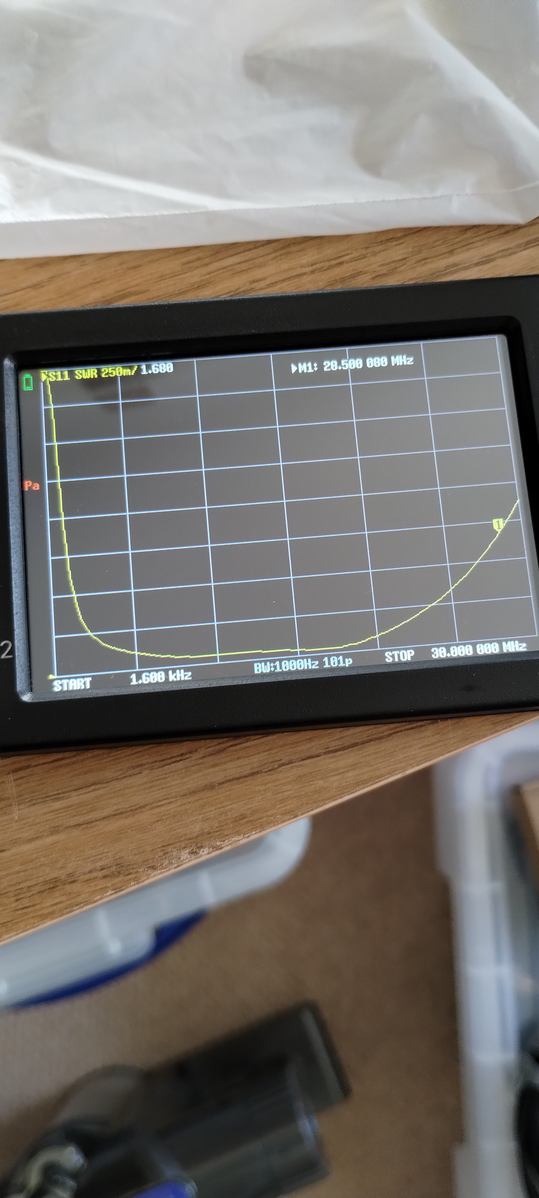
I know its a bit ‘Heath Robinson’, but I used some cable ties, fitted the capacitor again, and the reading is significantly better.
For your testing, keep in mind that this is not a radiating device, and SWR is a radiation measurement.
By putting a resistor across the poles you are pretty much making a dummy load and a good dummy load always has a 1:1 SWR because it is absorbing (converting to heat) all the RF energy.
When you put a wire (radiating element) on it, you will get SWR measurements that show you how good your wire is. The transformer will be a part of the radiating element and have some effect, but not what you want to measure here.
Here you want to test how well it is transforming a high impedance into a low impedance across the bands. That is its job. Look at the trace that measures Resistance.
Your resistor across the poles should represent the radiating element. ~2500 ohm for an EFHW, ~450 for a EF Random Wire.
A 9:1 can transform 450 ohm into 50 ohm, and a 49:1 can transform 2500 ohm into 50 ohm. Test your transformer on the VNA for the resistance trace and it should be flat near 50 ohm across the bands and may rise as it gets into the high bands.
If it’s good on that test, now go out into the back yard and add your wire and test for SWR. Trim the length until you get dips at the freqs you are targeting.
You may find that a 49:1 WITH a wire only brings your SWR around the 2:1 range. Now you can test your wire with a 64:1 and see if that brings all the SWR readings down a little lower. You are fine tuning at this point with different winding, longer coax, one or more radials, elevated radials…
Then you leave your back yard and climb a summit and all of that changes. But it’s too late you’re already on the summit.
Start calling CQ.
The question you need to ask is “It’s on the internet… but is it accurate and truthful information.” The answer to that comes from experience.
One thing that helps is info posted on active sites like this gets lots of eyeballs from people with understanding and experience. People posting pish and nonsense get short shrift from their peers on here and posts should get corrected or deleted. Posts to blogs and / or Youtube may contain genuine errors or just be the output of the deranged. If there are few views or comments and you don’t fully understand the issues (because we all start out knowing nothing about anything) then you may not realise you are not following the best info. With time and practice it gets easier.