So, of course, if I’m going to suggest an alternative approach, I should come with a more explicit design…
Here is a model - I haven’t built it yet. But hopefully it is close enough that someone can try it out fairly easily.
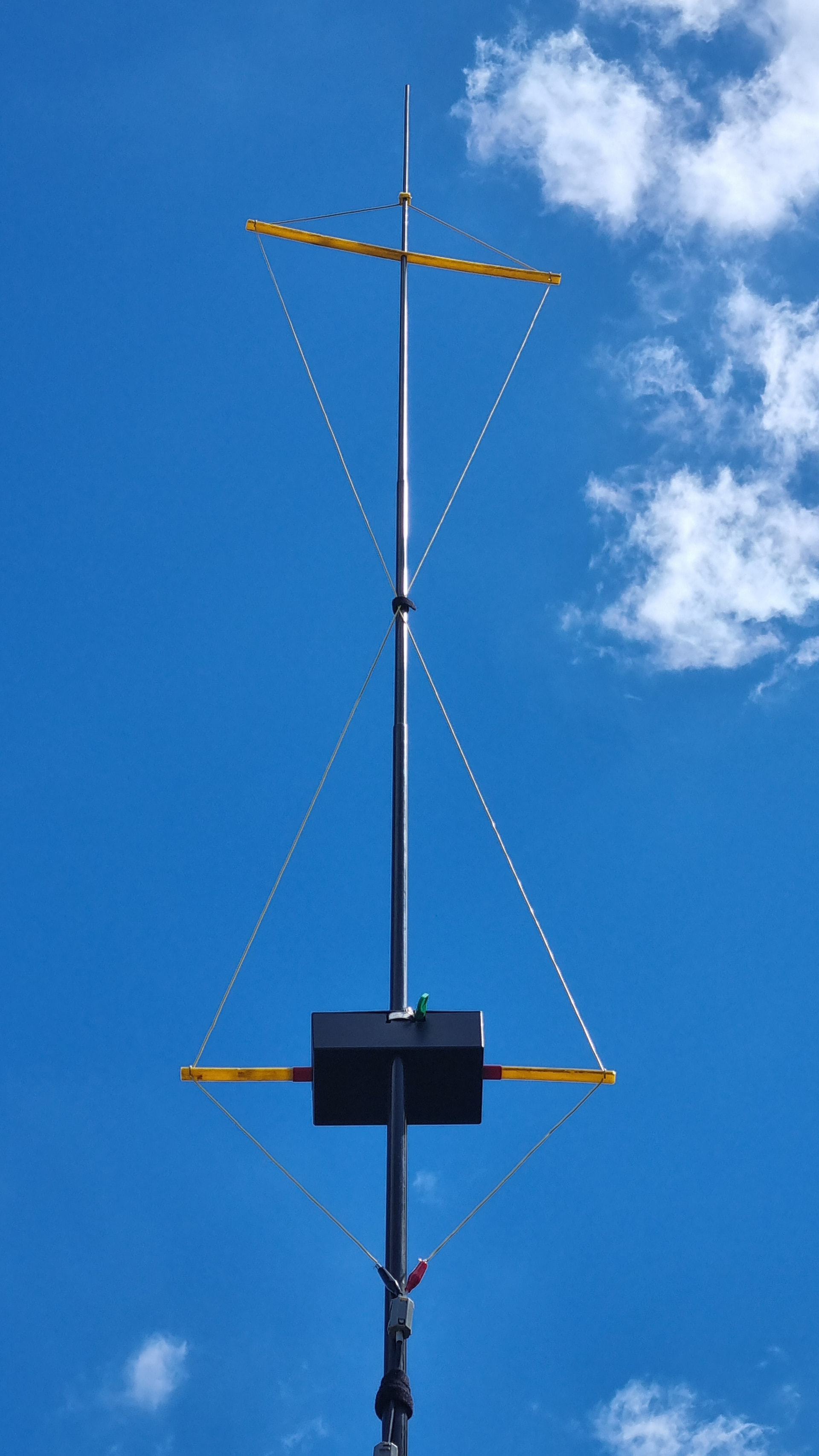
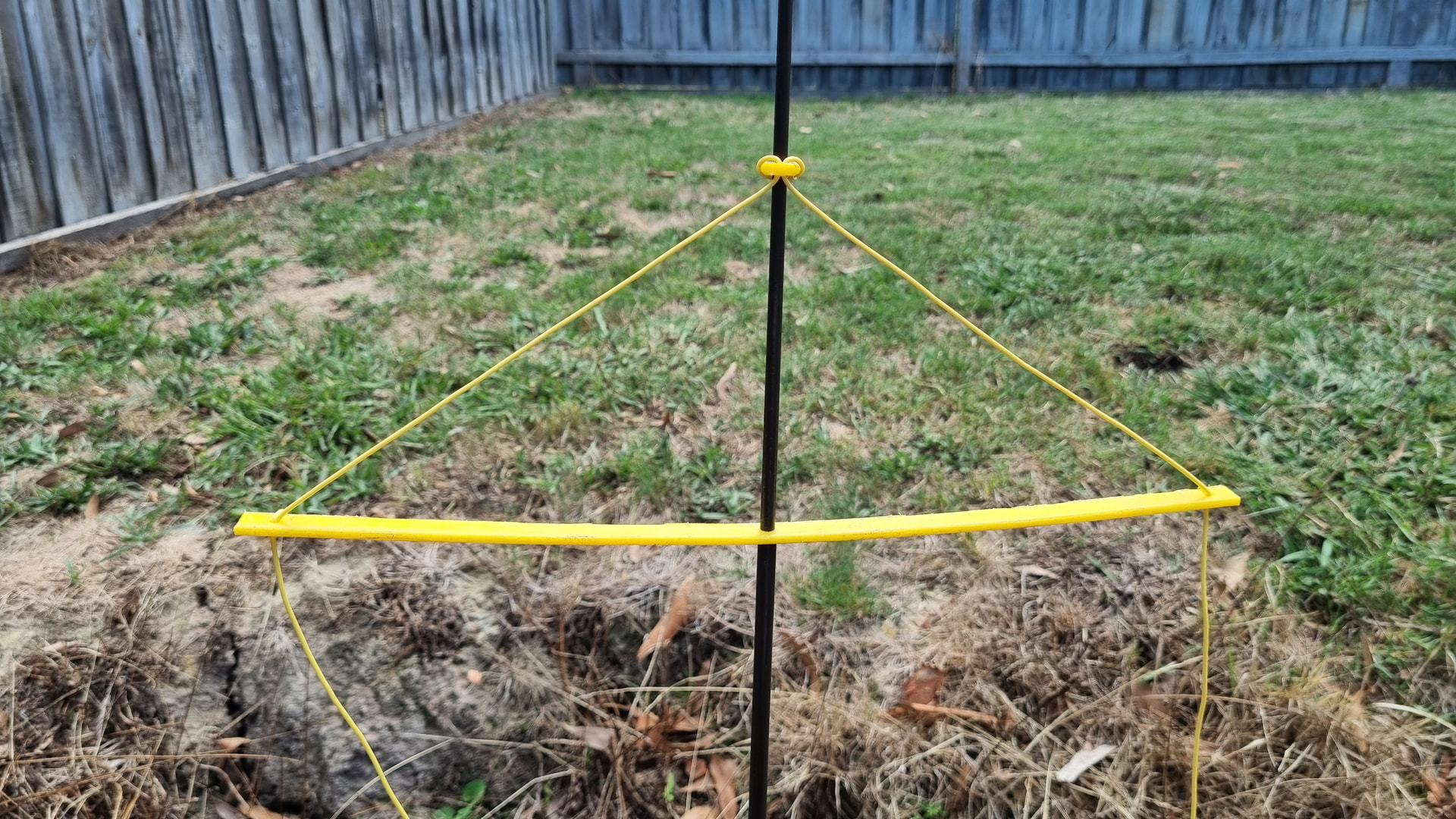
We’ll start with two rectangular loops using 1mm wire (AWG #18 or BWG #19 for those who prefer). Each loop is 600mm tall and 526mm wide, fed in the short side. I’d probably pass the horizontal wires through pieces of polyethylene (“polythene?”) tubing. Because the vertical sides are longer than the horizontal ones, you can just give the loop a half twist and lay the two pieces of tubing side-by-side to collapse it for transport.
Then you need a support to hold the two loops apart, about 600mm apart. That gives a total length of 1.8m, plus a bit for a handle, mounting, etc. Ideally the antenna would be mounted with the bottom about 2m above the ground. Both loops are mounted with the feedpoint towards the center, and fed in phase. You can hang the whole antenna from a rope tied to the top if you add some additional ropes between the elements to take the tension off the feeders. Or arrange some sort of clips to attach the horizontal spreaders to the side of your telescoping mast.
The exact spacing between the too loops isn’t critical, either. Wider spacing gives a bit more gain, but makes the structure more unwieldy.
Hmmm… isn’t the feed line matching going to be a problem?
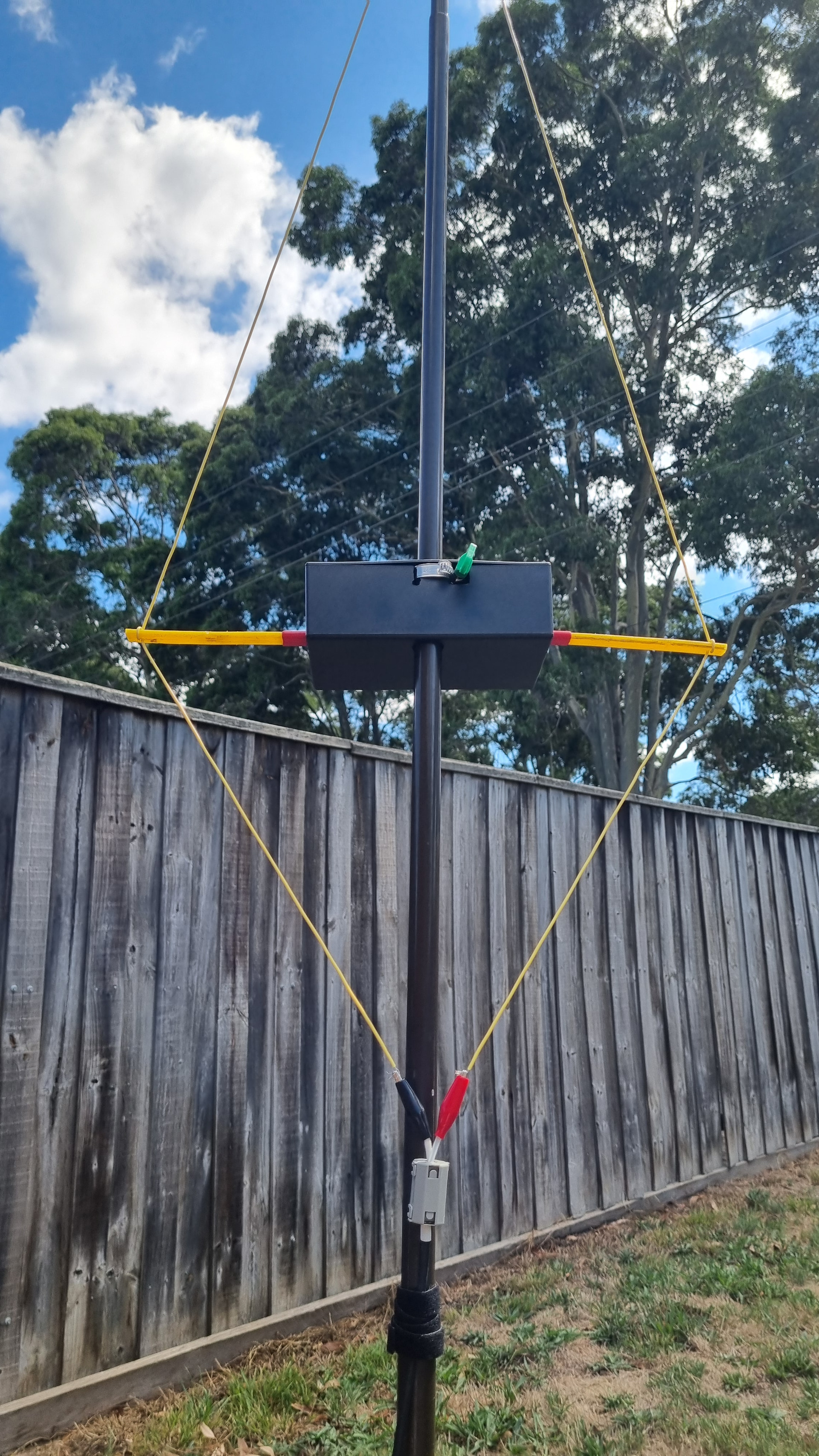
Well, each loop is crafted to have a feedpoint impedance of 100 ohms. (If you measure them individually, expect something like 110 ohms with resonance at 142.5 MHz - I had to adjust for mutual coupling between them.) So all we need to do is to run 100 ohm feedline from each loop to a common point, connect the two in parallel, and we get a 50 ohm load for coax. (A 1 : 1 balun wouldn’t be a bad idea at that point, but it may still work without one.)
Oh, don’t happen to have any RG-62 or other 100 ohm feedline handy? No problem. Take two pieces of 50 ohm coax the same length, solder the shields together at each end, and use the center conductors as a 100 ohm balanced line. Actually, in this case, cut 4 pieces, all the same length: the actual length isn’t important, as long as the completed assembly reaches between the two loops, but the feed to each loop must be the same length.
The result? About 5 dB over a dipole. SWR is 1.043 at 144.25 MHz rising to 1.33 at 146 MHz.
Not quite as narrow as the original, but about the same gain, the loops fold up easily, and it isn’t as prone to detuning.

")